KCS & KVLCC2 hulls: from fitting to deformation and design exploration
Fitting existing hull forms
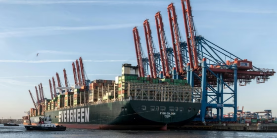
The Component-Based Ship Workflow in CAESES provides a structured method for creating parametric ship hull geometries for modern ship design and naval architecture. This approach also enables the parametric fitting of benchmark ship hulls developed by the Korea Research Institute of Ships and Ocean Engineering (KRISO), including the KCS (KRISO Container Ship) and KVLCC2 (KRISO Very Large Crude Carrier). These hulls provide high-quality datasets widely used for CFD validation, hydrodynamic analysis, and ship flow studies. Parametric versions of these models are available in the CAESES sample library for simulation-driven ship design and optimization.
Comparison between original and parametric geometry
A comparison of the station curves between the original hull geometry (red) and the parametric reconstruction created with the Ship Modelling Workflow (green) demonstrates the accuracy of the fitting process while enabling parametric control for further hull form exploration and optimization.
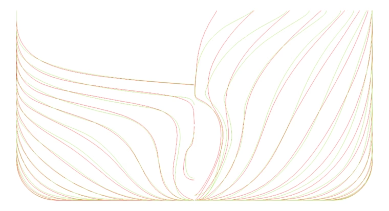
Figure 1: Stations Comparison for KCS
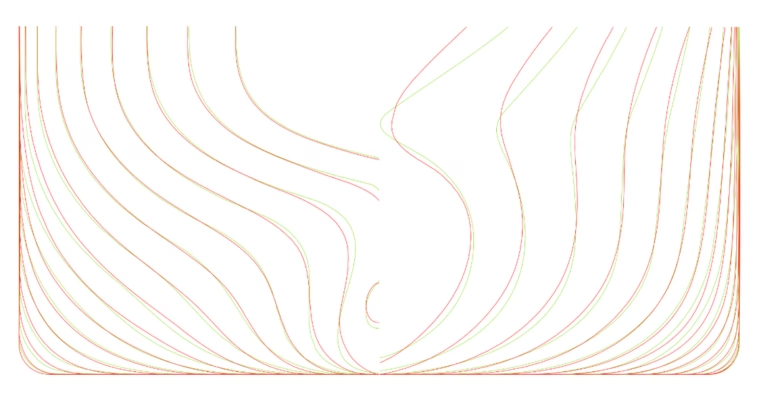
Figure 2: Stations Comparison for KVLCC2
A comparison of the hydrostatics between the original geometry and the parametric ship modeling workflow (SMW) model is also performed.
Table 1: Hydrostatics Comparison for KCS
| Name | Unit | Original | SMW |
| LPP | m | 230.00 | 229.95 |
| Displacement | m3 | 52030 | 52828 |
| Wetted surface (w/o rudder) | m2 | 9530 | 9632 |
| Block Coefficient (CB) | - | 0.651 | 0.661 |
| Midship coeffiecient (CM) | - | 0.985 | 0.985 |
| LCB (forward +) | % | -1.48 | -0.89 |
Table 2: Hydrostatics Comparison for KVLCC2
| Name | Unit | Original | SMW |
| LPP | m | 320.00 | 319.62 |
| Displacement | m3 | 312622 | 312993 |
| Wetted surface (w/o rudder) | m2 | 27194 | 27759 |
| Block Coefficient (CB) | - | 0.8098 | 0.8120 |
| Midship coeffiecient (CM) | - | 0.998 | 0.998 |
| LCB (forward +) | % | 3.48 | 3.55 |
From KCS to KVLCC2
Both parametric hull models use the same Ship Modeling Workflow (SMW) parameterization in CAESES, including:
Because both hulls are generated using the same parametric modeling framework, they belong to the same parametric hull design family, even though they represent different ship types. The KCS is a container ship, while the KVLCC2 is a tanker, resulting in significant differences in hull fullness, proportions and cargo capacity requirements.
Due to the shared parameterization structure, however, the SMW model enables a smooth geometric transition between the two hull forms. By adjusting a single design variable, the geometry can continuously morph from the KCS hull form to the KVLCC2 hull form. This demonstrates the flexibility of parametric ship hull modeling and shows how a unified parameterization can represent a wide range of ship hull designs within one parametric framework.
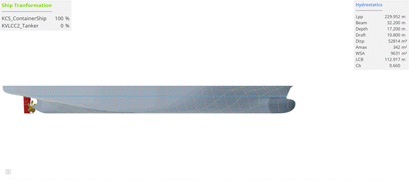
Animation 1: From KCS to KVLCC2 (3D perspective)

Animation 2: From KCS to KVLCC2 (Aft & Fwd Views)
In the animations, ship appendages including the rudder and propeller are also incorporated to provide a more realistic representation of the propulsion configuration. The propeller geometries are based on designs created using the Advanced Propeller Workflow in CAESES and imported into the project as STEP files for simulation. The KCS uses the 5‑bladed KP505 propeller, while the KVLCC2 is equipped with the 4‑bladed KP458 propeller, both designed within the same parametric workflow before integration into the model. The radial distributions of the propeller design parameters for both propellers are shown below, highlighting the key geometric characteristics of the two propeller configurations.
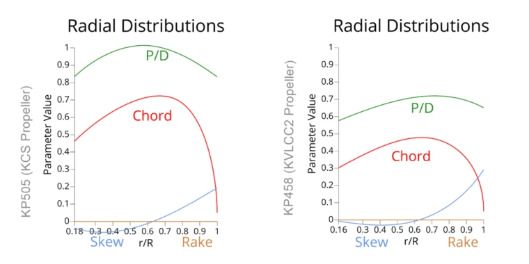
Figure 3: Radial Distributions fro KP505 & KP458 Propeller Models
Deformation
Based on these reference models, the identified parameters of the Ship Modeling Workflow parametric hull model were defined as the baseline geometry. This baseline served as the starting point for additional targeted shape modifications, introducing further geometric flexibility to analyze the hydrodynamic impact of local hull variations. Two shape deformation techniques were applied.
First, free-form deformation was used on the KCS bulbous bow, enabling smooth and controlled bulb shape variations while preserving surface continuity. This allows systematic exploration of alternative bulbous bow designs without compromising hull geometry quality. Second, RBF-based B‑Rep morphing was applied to the aftbody of the KVLCC2 hull, enabling precise and localized stern geometry modifications directly on the CAD model while maintaining high geometric fidelity.
Together, these methods demonstrate how partially parametric deformation techniques can be applied to ship hull models to enable targeted design exploration and hydrodynamic optimization within a simulation-driven design framework. The animations below illustrate the influence of the four design variables used in each partially-parametric model.
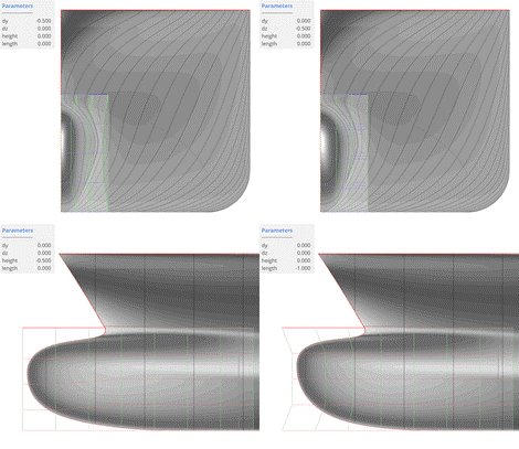
Animation 3: KCS Free-Form Deformation Bulb - 4 Design Variables
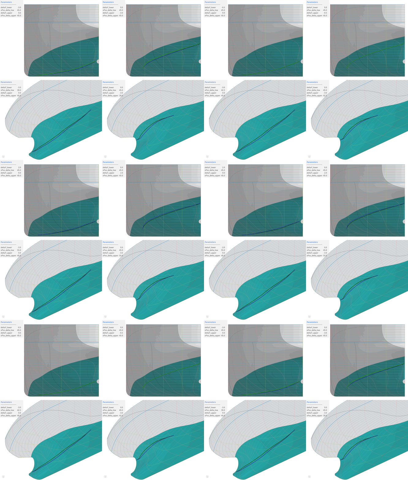
Animation 4: KVLCC2 Aft Region Brep Morphing – 4 Design Variables
Simulations with SHIPFLOW
SHIPFLOW is a Computational Fluid Fynamics (CFD) software specialized in the hydrodynamic analysis of ships and marine propellers. It is widely used in naval architecture for predicting resistance, propulsion performance, and flow characteristics around ship hulls. CAESES is well connected with SHIPFLOW, enabling seamless integration between parametric geometry modeling and hydrodynamic simulation. Through this connection, hull forms created and modified in CAESES can be directly transferred to SHIPFLOW, allowing efficient design exploration, automated simulations, and optimization of ship performance.
KCS setup – Resistance simulation
The original KCS design point corresponds to a design draft of 10.8 m and a service speed of 24 knots, conditions for which the bulbous bow geometry was optimized. This configuration serves as the baseline hull design for evaluating hydrodynamic performance. To assess performance across different operating conditions, additional scenarios were considered: a reduced draft of 9.5 m representing lighter loading, slow steaming at 18 knots for energy-efficient operation, and a high-speed condition of 26 knots.
Hydrodynamic simulations were performed using XPAN from SHIPFLOW, a potential-flow solver widely used for ship resistance prediction and hull-form evaluation. A fine computational mesh was applied to capture the flow characteristics around the hull and bulbous bow region. The analysis focused on key resistance components, including frictional resistance (Rf) and wave-making resistance (Rw), providing insight into the vessel’s hydrodynamic performance across operating conditions.
KVLCC2 setup – Self-propulsion simulation
The KVLCC2 baseline configuration corresponds to a design draft of 20.8 m and a service speed of 15.5 knots. The study focused on self-propulsion simulations to evaluate the interaction between the ship hull and propeller. Simulations were conducted using the XCHAP from SHIPFLOW, a RANS solver that combines propeller – hull interaction modeling with propulsion analysis. Calculations were performed at model scale using a coarse mesh, enabling the evaluation of multiple design variants with reasonable computational cost.
Propulsion was modeled using a Wageningen B‑series propeller, a widely used reference propeller series in naval architecture and hydrodynamic studies. The evaluation focused on key propulsion metrics, including total resistance (RS), power delivered (PD), and total propulsive efficiency (ηDS). These parameters provide a comprehensive assessment of propulsion performance and energy efficiency.
Design of Experiments (DoE)
For each partially-parametric model, four design variables controlled the geometric modifications. The Sobol sequence sampling method was used for design space exploration, providing well distributed coverage of the parameter space. Following common DoE guidelines, typically 5 to 10 samples per design variable, a total of 30 design variants were generated for each study. This sampling strategy provides a sufficiently rich and well-distributed dataset for the development of surrogate models, enabling the training of reliable machine learning models to approximate the underlying simulation responses.
KCS resistance (DoE)
Resistance simulations were performed at 18 knots and 26 knots to evaluate hull performance under different operating conditions. For each of the 30 sampled designs, flow-field visualizations were analyzed to understand the hydrodynamic effects of geometric variations. The animations illustrate pressure distribution, streamlines, and wave elevation, providing insight into how bulb geometry modifications influence flow behavior and ship resistance across the two operating scenarios.
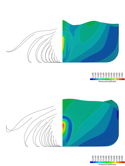
Animation 5: Pressure Distribution and Streamlines for KCS Design Variants at 18 kts (top) and 26 kts (bottom)
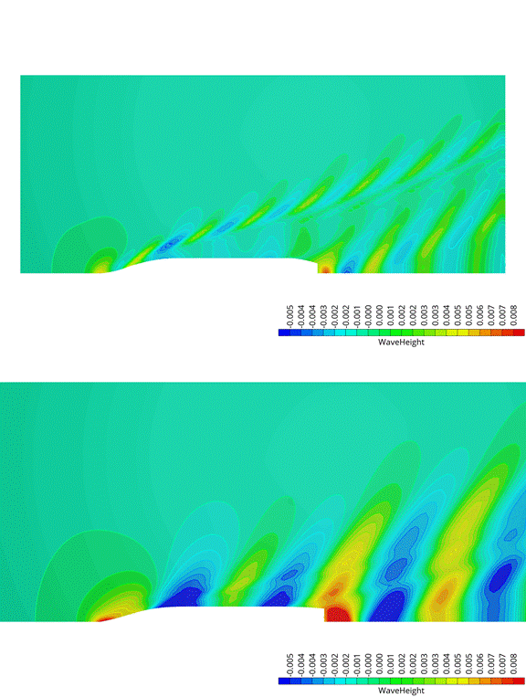
Animation 6: Wave Height for KCS Design Variants at 18 kts (top) and 26 kts (bottom)
During post-processing, correlation and regression analyses in CAESES were used to evaluate how the design variables influence hydrodynamic performance. These analyses help identify parameter sensitivities and trends, revealing how each variable affects ship resistance within the explored design space.
A key observation emerges when comparing results at the two operating speeds. Changing speed significantly alters the influence of the design variables on wave-making resistance, showing that parameter importance varies across operating conditions. This effect is also visible in the animations. At 18 knots, the results favor a shorter and more slender bulbous bow, which helps reduce wave resistance during slow steaming. At 26 knots, the design exploration leads to a longer and fuller bulb, better suited for higher-speed operation and different wave patterns.
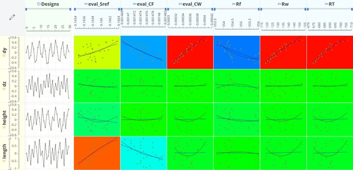
Figure 4: Correlation & Regression Analysis of Resistance Results for KCS Design Variants at 18 kts
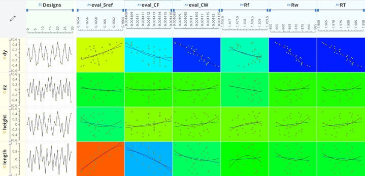
Figure 5: Correlation & Regression Analysis of Resistance Results for KCS Design Variants at 26 kts
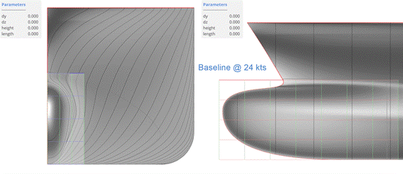
Animation 7: KCS Baseline and Optimized Design Variants
KVLCC2 self-propulsion (DoE)
Sobol sampling was used to generate 30 design variants based on four design variables, ensuring a well-distributed design space exploration. The animations illustrate pressure distribution, streamlines, and nominal wake for the different designs. These visualizations help analyze how stern geometry variations influence hull flow, propeller inflow and overall propulsion performance, providing insight into the vessel’s hydrodynamic and propulsive efficiency.
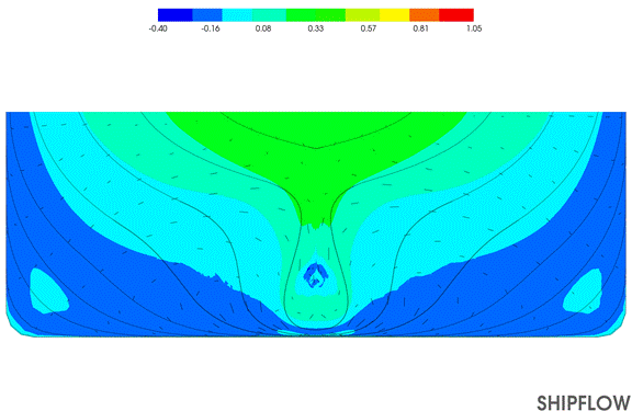
Animation 8: Pressure Distribution and Streamlines for KVLCC2 Design Variants at 15.5 kts
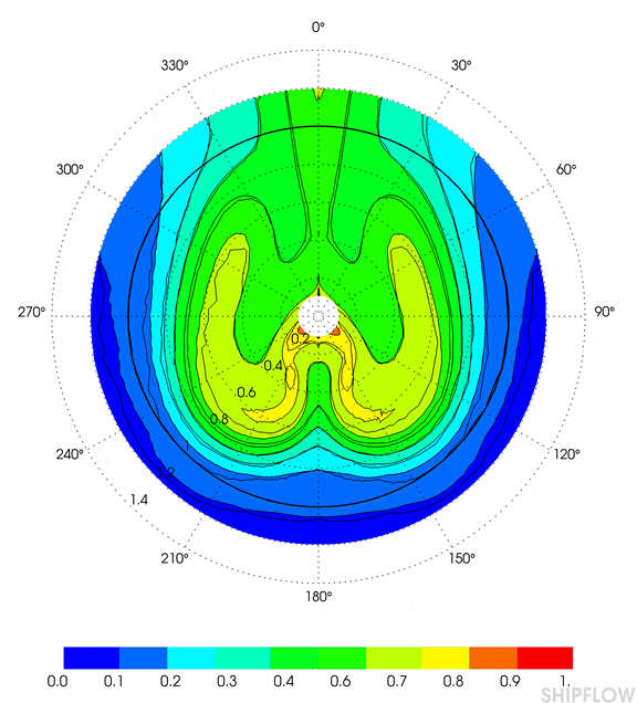
Animation 9: Nominal Wake for KVLCC2 Design Variants at 15.5 kts
Correlation and regression analyses were carried out during the post-processing stage using CAESES, allowing the influence of the design variables on the hydrodynamic performance to be systematically evaluated. The analysis indicates that a wider skeg in the lower region tends to increase the overall resistance of the vessel. However, at the same time, an increase in total propulsive efficiency (ηD) is observed. In several cases, the improvement in propulsive efficiency is larger than the corresponding increase in resistance, resulting in an overall reduction in the required propulsion power.
This behavior is partly related to the characteristics of the ITTC extrapolation method, which is commonly used for resistance and propulsion analysis at model scale. While the method provides consistent comparative trends for design evaluation, the exact balance between resistance and propulsion efficiency improvements may not fully represent the behavior at full-scale operating conditions.
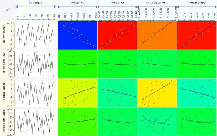
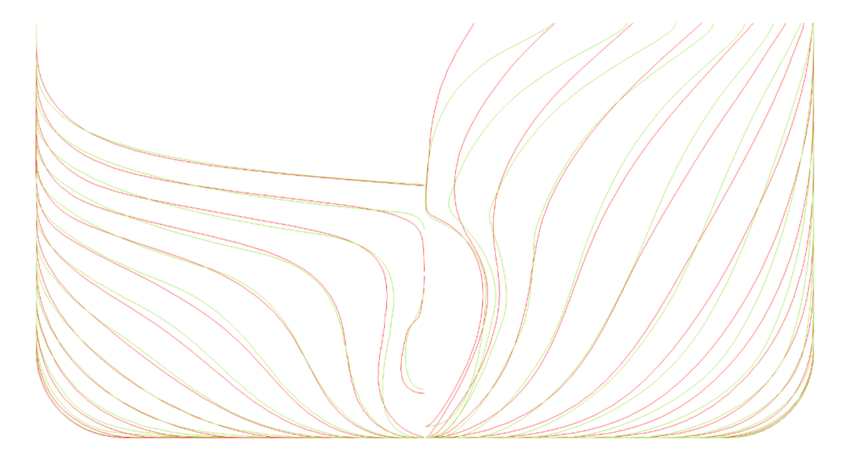
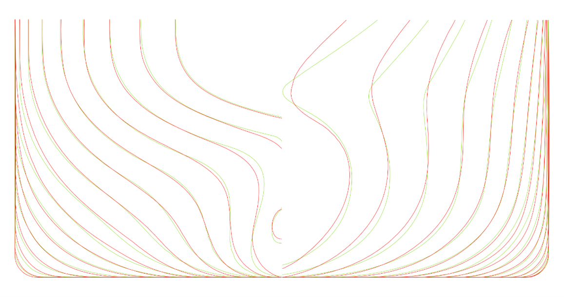
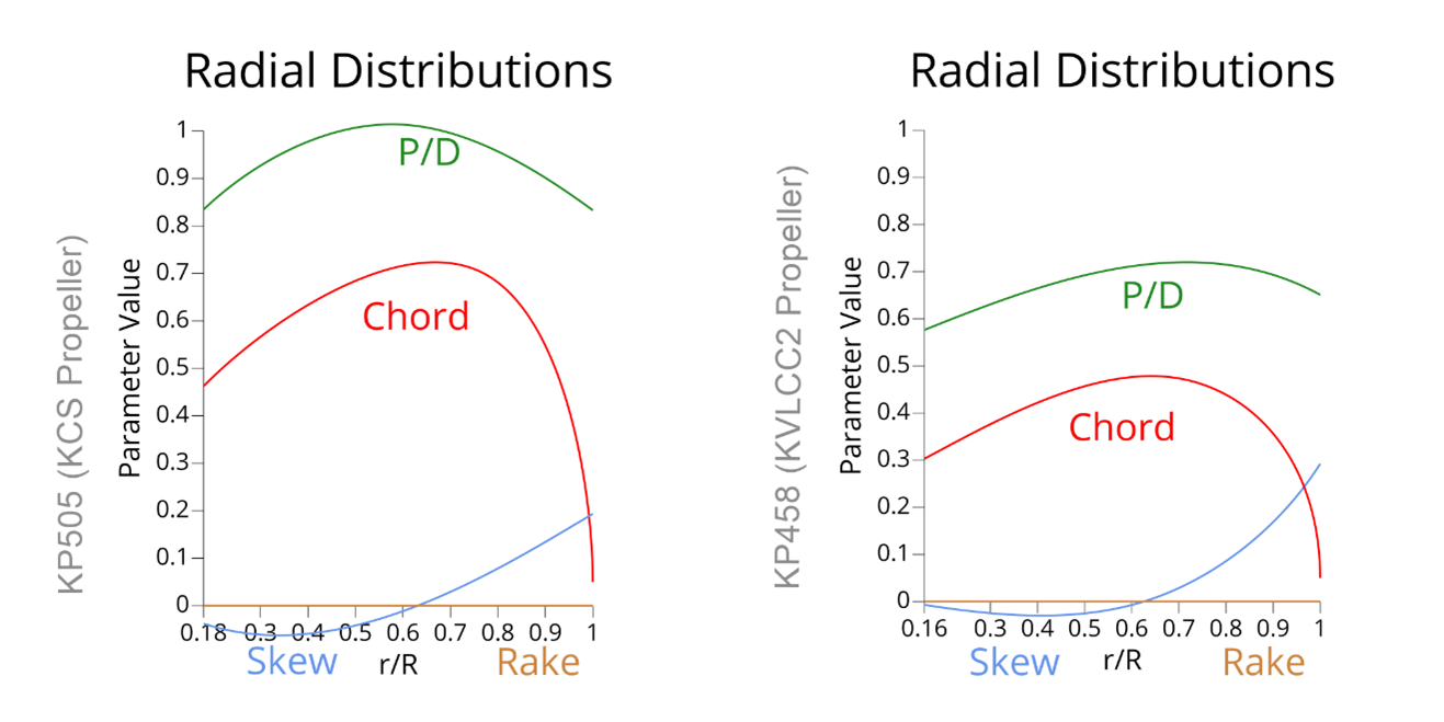
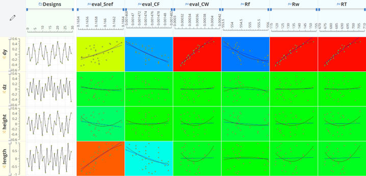
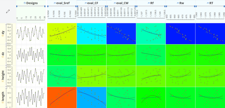
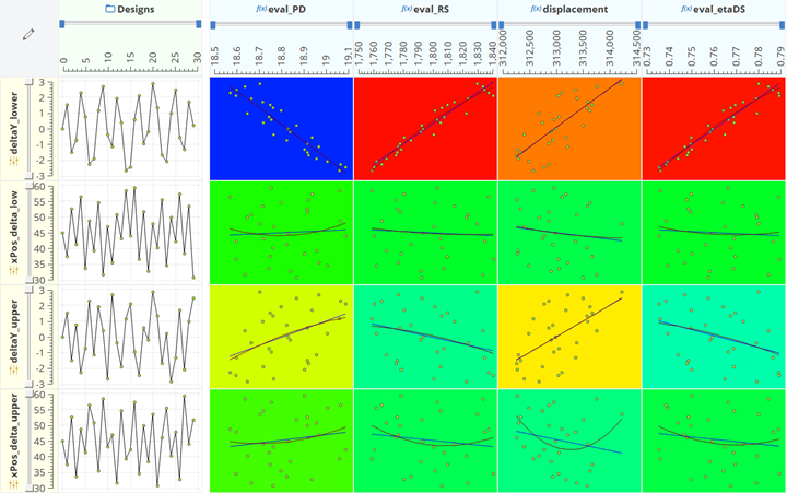
Figure 6: Correlation & Regression Analysis of Self-Propulsion Results for KVLCC2 Design Variants at 15.5 kts
Conclusion
This study demonstrates the capabilities of fully parametric modeling using the Ship Modeling Workflow in CAESES, successfully reproducing existing hull forms such as KCS and KVLCC2. Partially-parametric modeling was also applied, highlighting the robustness and efficiency of parametric approaches.
A seamless integration between CAESES and SHIPFLOW enabled an automated simulation-driven design framework. Resistance simulations were performed using the XPAN solver, while self-propulsion analyses were conducted with XCHAP.
The results highlight the power of simulation-driven design, where numerical simulations combined with parametric modeling and structured design exploration reveal complex relationships between hull geometry and hydrodynamic performance. This approach enables designers to identify optimal design trends and make informed decisions early in the design process.
The study also emphasizes the increasing importance of data-driven engineering. Managing and analyzing large volumes of simulation data allows meaningful insights to be extracted, supporting smarter design processes and more efficient development of high-performance ships. The integration of Artificial Intelligence (AI) and machine learning techniques further enhances this process by enabling the development of predictive models that can approximate simulation results, identify complex patterns within the design space, and support faster design exploration and optimization.
Overall, the combination of parametric modeling, simulation-driven design, and data-driven engineering provides a powerful and structured workflow for modern ship design, enabling efficient progression from concept development to optimized hull performance.