Hydrodynamic optimization of a catamaran houseboat for inland waterways
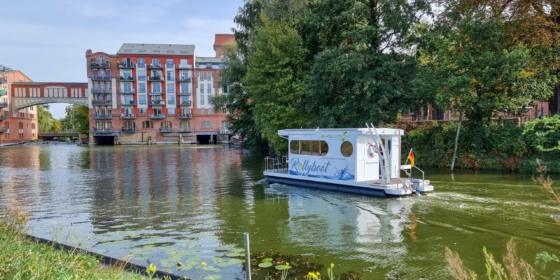
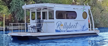
In recent years, the demand for houseboats has increased significantly, accompanied by a growing emphasis on environmentally friendly vessel designs due to the pressing need to address climate change. The company Rollyboot has responded to this trend with its fully electric houseboat, the “Rollyboot Evolution”, presenting a forward-looking solution. It is commonly known that hull geometry significantly affects wave resistance and overall hydrodynamic performance. However, like much of the houseboat industry, Rollyboot has not yet considered hull form optimization to achieve additional performance gains. A unique feature of Rollyboot is its use of modular float structures, which provides an ideal foundation for improving efficiency with minimal design changes and resource expenditure. In addition, the floaters are produced using the rotational molding process, which allows the resulting plastic hollow bodies to be formed in any desired geometry.
This study investigates the influence of modifying the bow shape on the vessel’s total resistance. A parametric model was developed and subjected to a RANS-based multi-objective optimization. While traditional optimization methods are resource-intensive due to the high number of design variables, Principal Component Analysis (PCA) offers a promising solution by reducing the design space while preserving variability, potentially making the optimization process faster and more cost-effective. To prove this thesis, a comparative optimization was conducted using a parameter-reduced Karhunen – Loève Expansion (KLE) model.
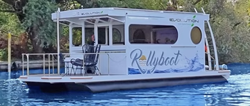
Rollyboot Evolution
Approach and Objectives
The research utilizes a parametric modeling approach realized within the CAESES environment for both CAD design and optimization. The optimization process integrates the NSGA-II algorithm alongside the Karhunen – Loève Expansion (KLE) method to reduce the dimensionality of the design space. Computational Fluid Dynamics (CFD) analyses are performed using the viscous RANS solver FS-Foam and the automated mesh generation tools provided by DNV’s Hydrodynamics Department.
The study conducts a comparative evaluation between a conventional CAD-based optimization model and a reduced-order KLE model, assessing both in terms of the attained hydrodynamic performance and computational efficiency. This approach is intended to demonstrate that it is possible to find a better shape for the houseboat catamaran hull form, and that a reasonable solution can be found faster and more cost-effectively by using principal parameters from the Principal Component Analysis.
Design Constraints and Parametric Model
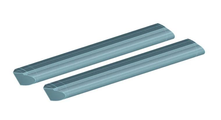
Simplified original Rollyboot floater model
The hull design is constrained by the existing dimensions of the Rollyboot platform, allowing only a 7 cm extension at the bow to maintain compatibility with mooring and modular construction. For production reasons, only the bow is changed in this study. Additionally, the new bow model must be suitable for both demihulls and use the same form, ruling out asymmetrical shapes.
The parametric model was developed using the CAD interface of CAESES 5, based on a general model structure used at DNV. The focus was on modifying the bow while keeping the middle and aft parts of the original Rollyboot baseline model unchanged. The bow model’s length includes the original bow module, plus the aforementioned 7 cm. The model is designed to explore the effects of bow shape on resistance, allowing for a bulbous bow and a flat vertical stem curve. However, the model excludes reverse bows due to geometric limitations.
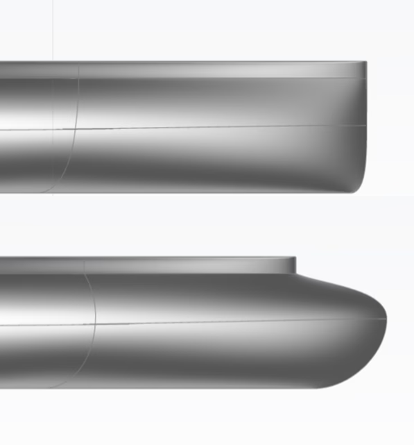
Shape variation of the stem curve in CAESES
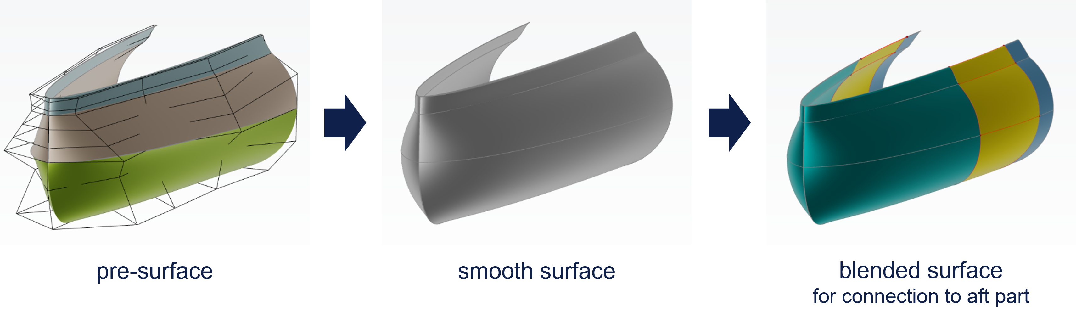
The model consists of three main surfaces:
- Pre-surface: Comprising three B‑Spline surfaces with 4x5 points, providing volume and a flat surface for platform fixing.
- Smooth surface: Ensuring smooth transitions between the B‑Spline surfaces.
- Blended surface: A fillet surface between the cross-section loft at the cut position and a defined point of the new bow model, ensuring smooth transition to the baseline model.
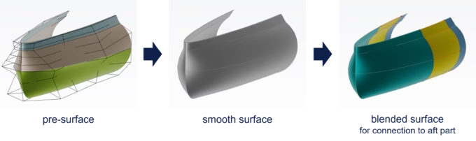
Parametric model (mirrored on Y-axis)
The parametric bow model features 23 free variables, categorized into four groups based on their influence on shape:
- Stem curve appearance (6 variables)
- Lower volume distribution (6 variables)
- Middle region (5 variables)
- Upper part and transition to middle section (6 variables)
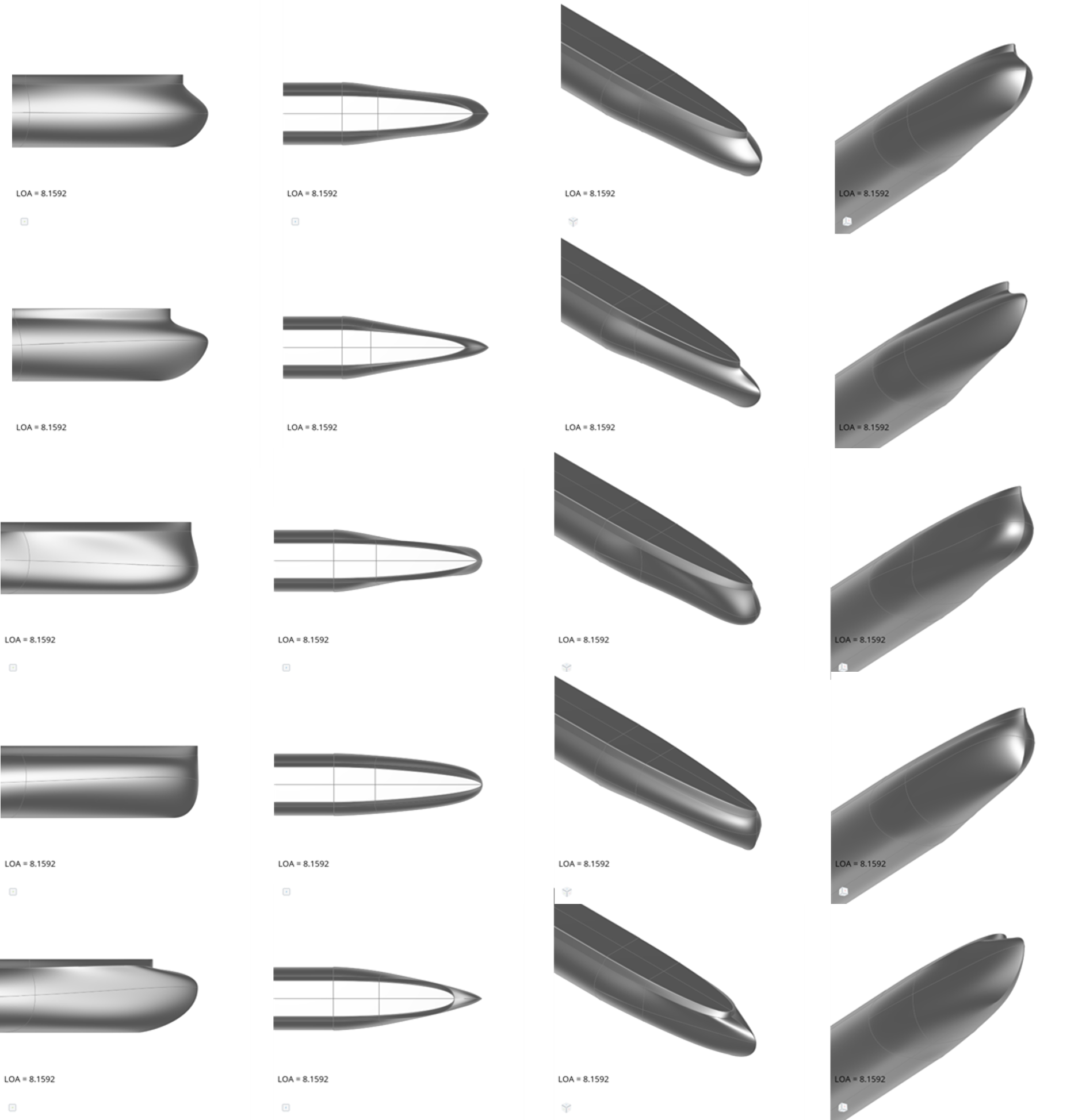
Finally, the full demihull model is closed with a BRep by merging the blended bow model with the baseline model shape. Five possible geometry variants are presented in the image below to illustrate the wide range of model variations.
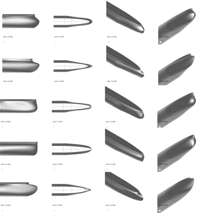
Geometry variation
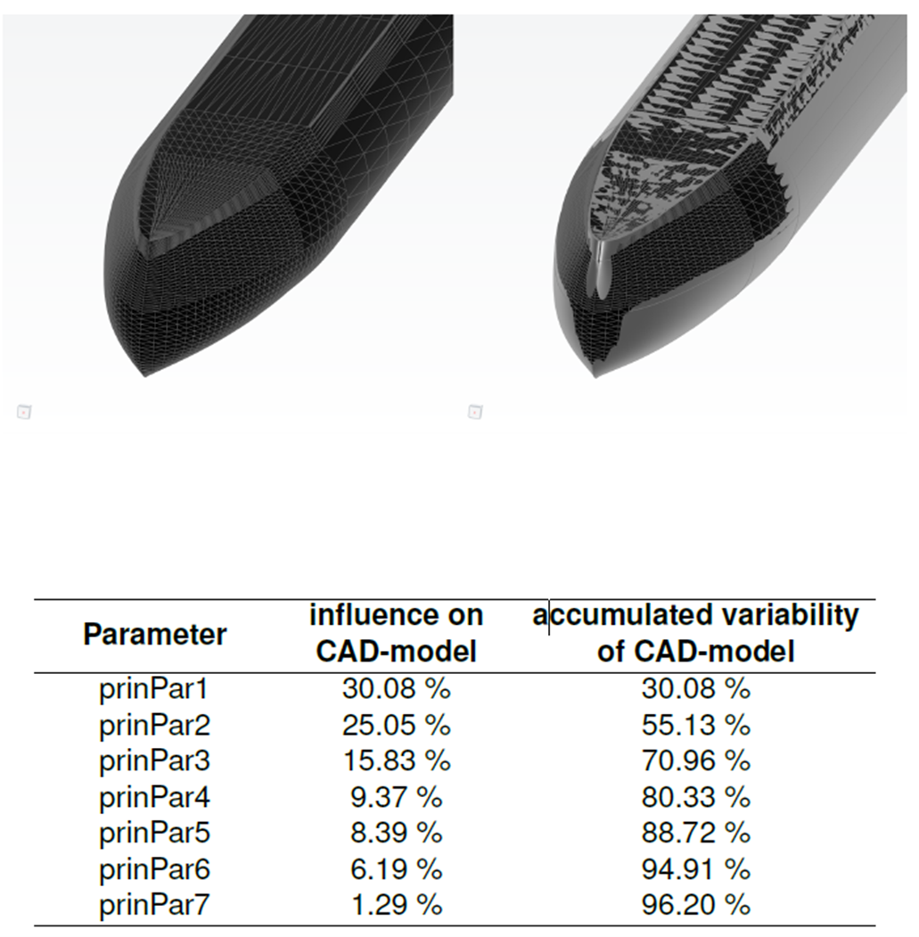
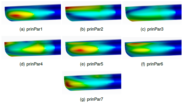
To reduce computational complexity, a Karhunen – Loève Expansion (KLE) model was created with the respective tool available in CAESES using 230 design samples. This reduced the number of parameters from 23 to 7 while preserving 96.2% of the model’s variability. The first principal parameter alone accounts for over 30% of the geometric variation, enabling efficient optimization with significantly fewer variables.
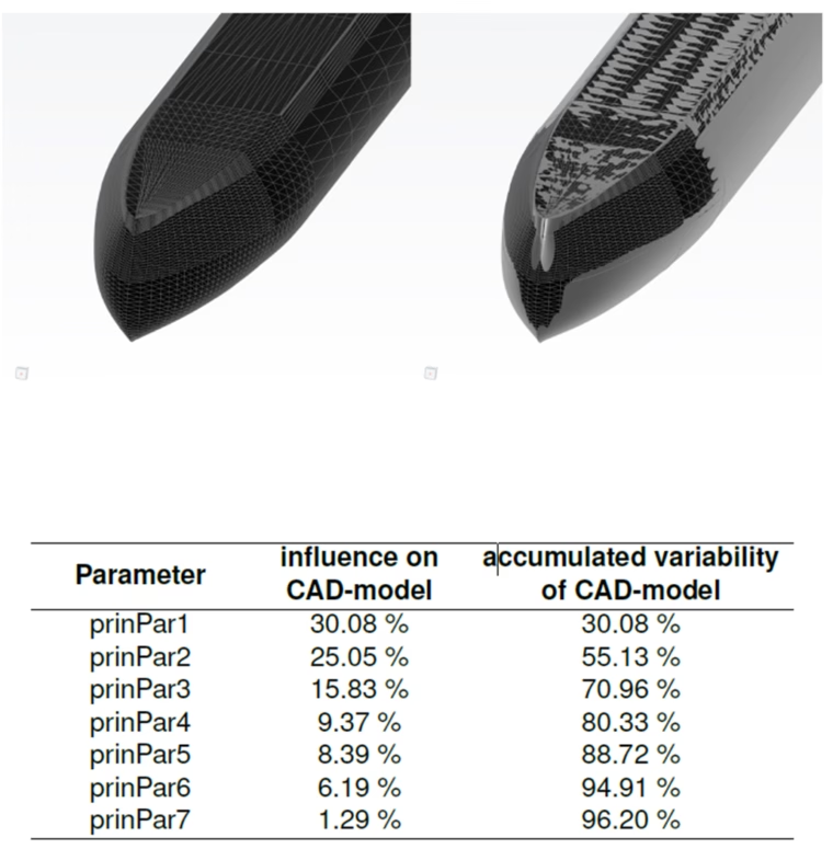
Variability of KLE model
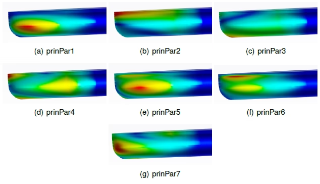
Principal Parameters
Preparation Phase
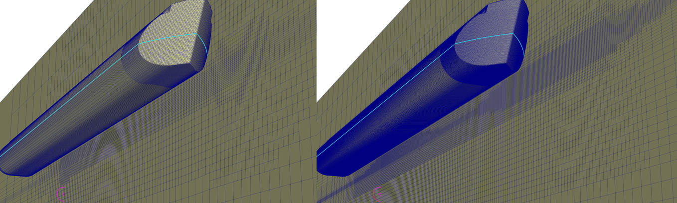
During the preparation phase, key aspects such as the selection of the CFD code, mesh quality assessment, a depth study, and a check of the hydrostatics were systematically evaluated.
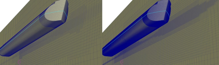
Mesh - coarse (left) and fine (right)
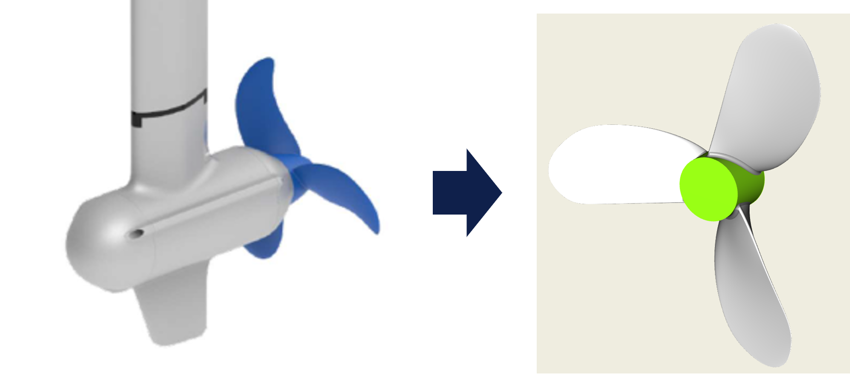
To validate the plausibility of the RANS simulations, the computed calm water resistance was compared with realistic propulsion data. According to the manufacturer, the Rollyboot reaches a speed of 7.8 km/h using a 6 kW electric motor. Since detailed propeller data was unavailable, a Wageningen B‑Series propeller was modeled using the online propeller tool from FRIENDSHIP SYSTEMS, incorporating available specifications from ePropulsion.
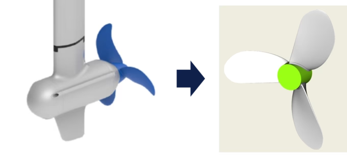
ePropulsion propeller (left) approximated with FRIENDSHIP SYSTEMS online propeller tool (right)
The resulting propeller showed a thrust of 1097 N and an efficiency of 0.42 at the target speed. In comparison, the CFD simulation predicted a resistance of approximately 800 N — about 27% lower. This discrepancy is attributed to unmodeled factors such as structural gaps, hull openings, fouling, and wind resistance.
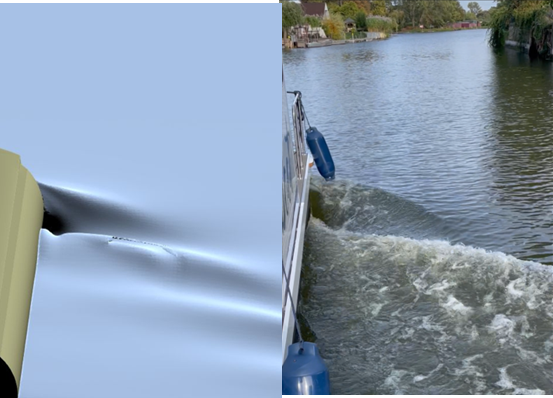
Additionally, the simulated wave pattern closely matched the real waves at this speed, further supporting the credibility of the CFD results.
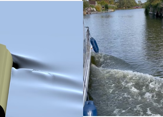
Wave pattern from simulation (left) compared to reality (right)
Optimization
To investigate the hydrodynamic behavior of the catamaran houseboat, the following setup is used:
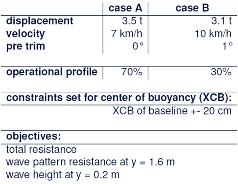
Two cases are considered important for the use of the Rollyboot.
Case A covers the most common scenario of a family (or friend group) of four people traveling with the boat for a weekend or holiday trip at an average cruising velocity of 7 km/h. Considering the empty weight of the Rollyboot Evolution (2,940 kg), an average weight per person of 75 kg plus 25 kg of provisions, and 100 kg for fresh water, the displacement for this case is assumed to be 3.5 t and evenly loaded.
Case B represents a transit scenario for one person cruising at a higher speed of 10 km/h. For this case, a displacement of 3.1 t and an aft trim of 1° is assumed.
Since reducing wave production is a key objective for the new model, wave pattern resistance and wave heights at different wave cut positions are monitored. The cuts at 0.2 m between the hulls and 1.6 m beside them are considered most relevant for optimization.
The optimization aims to minimize the hydrodynamic total resistance, the total wave pattern resistance at y = 1.6 m, and the maximum wave height at y = 0.2 m between the demihulls for both cases. The latter is particularly important, as initial simulations showed increased wave formation between the demihulls, which must be minimized to avoid wave impact on the platform. Minimizing wave pattern resistance at the 1.6 m cut helps reduce wake wash around the boat.
As Case B is considered less critical, a weighting of 30% for Case B and 70% for Case A is applied, reflecting the operational profile. This results in a multi-objective problem with three objectives. All values are presented relative to the baseline model for clearer and more straightforward comparison.
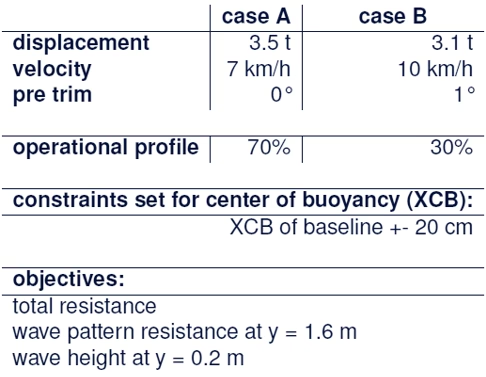
Optimization setup
The center of buoyancy was constrained to ±20 cm from the baseline for both cases. Each generated design’s draught was determined based on hydrostatics and the specified displacement. Two multi-objective optimizations were conducted using the NSGA-II algorithm in CAESES: one with the standard CAD model (23 parameters) and one with the reduced-order KLE model (7 principal parameters). Both setups used a Sobol sequences for the initial sampling — 230 valid designs for the CAD model and 70 for the KLE model. Simulations were run with a coarser mesh on 16 processor cores.
Results
Results showed consistent improvements in total resistance for both cases compared to the baseline, with the best designs significantly outperforming it.
Key findings were:
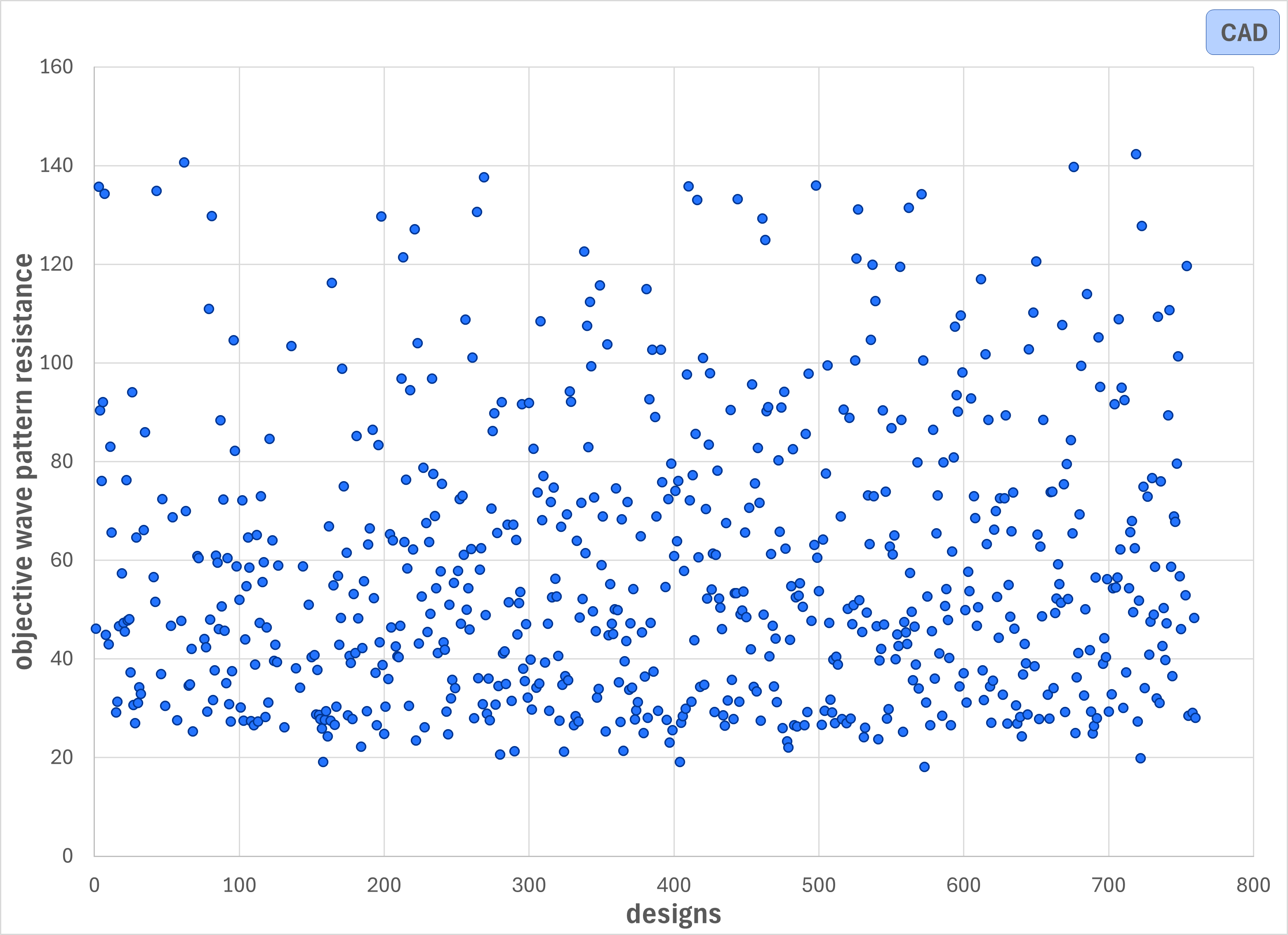
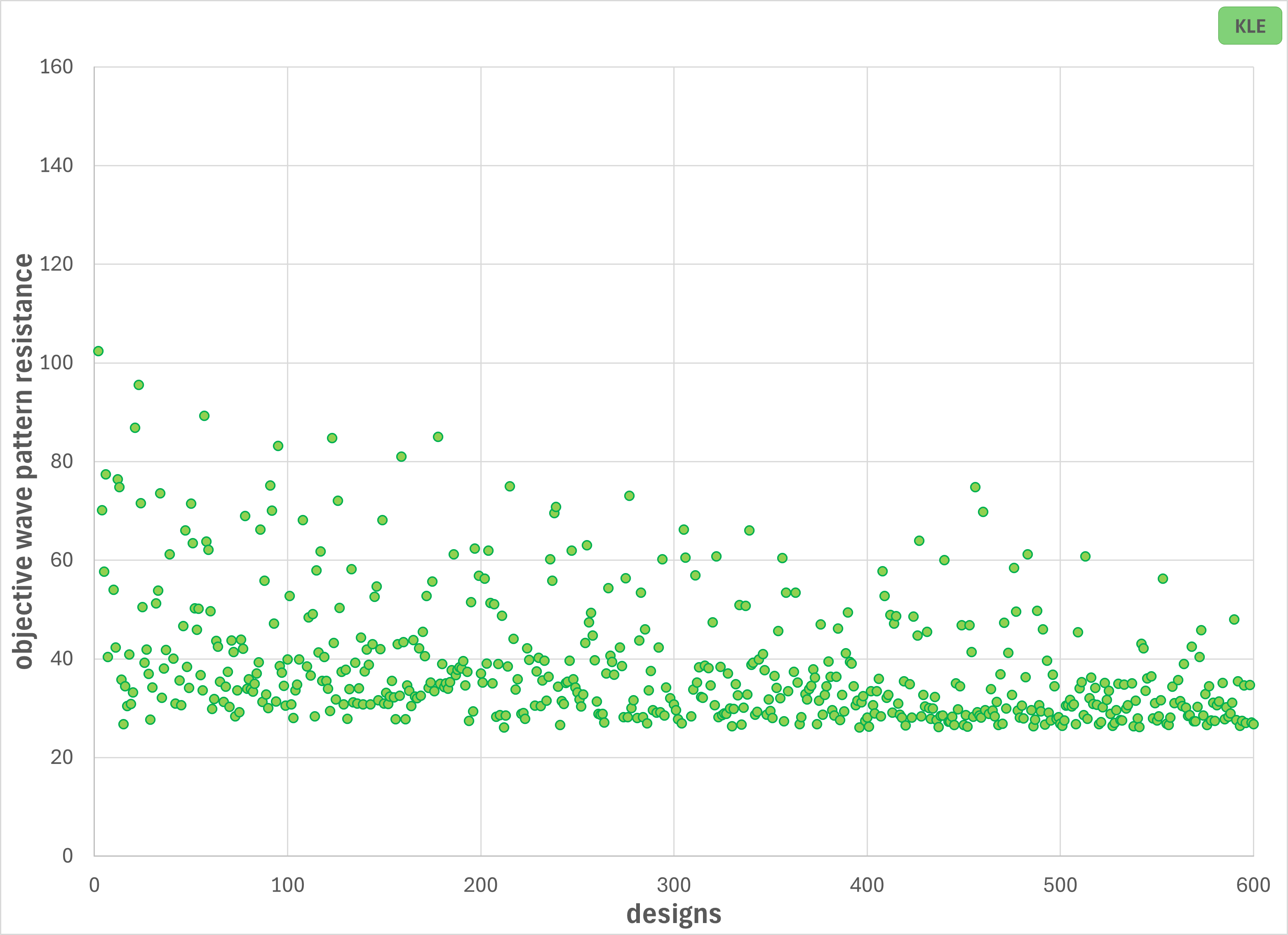
- The NSGA II is stopped for the KLE approach when the objectives converged (556 valid designs), while for the conventional CAD approach no convergence could be identified and thus the algorithm stopped after 661 designs (time and resource limit).
- Great savings of resources can be realized when running the DoE phase of the optimization (230 CAD designs compared to only 70 with KLE model, capturing 96% of variability with 7 principal parameters).
- Additional time and resources are needed to compare models when using NSGA II and RANS in combination.
- Good designs could be achieved for both the KLE and CAD model, with the best designs delivering 30 – 40% improvement in total resistance.
- The best designs were determined by low values for the 3 objectives, low change of XCB in case A and suitability for the task.
- One of the CAD designs was the most convincing and was proposed as final design to Rollyboot.
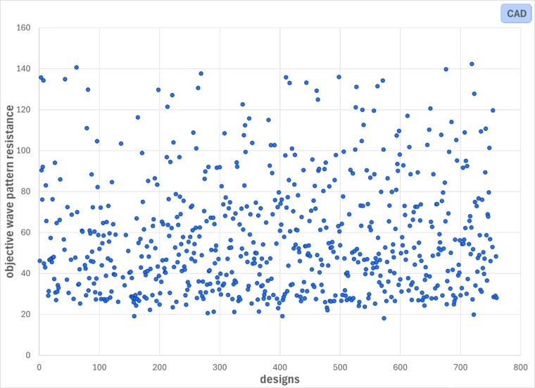
Convergence of computation for CAD designs
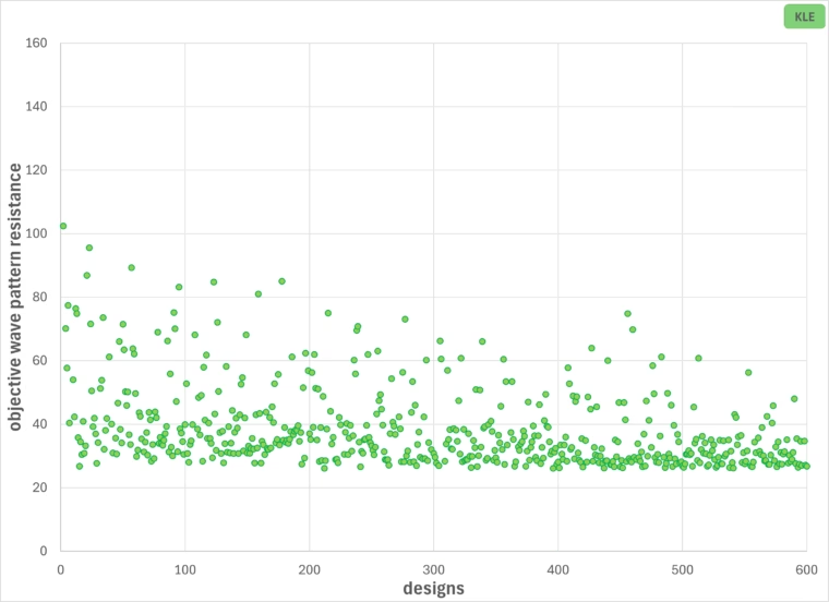
Convergence of computation for KLE designs
Best Design
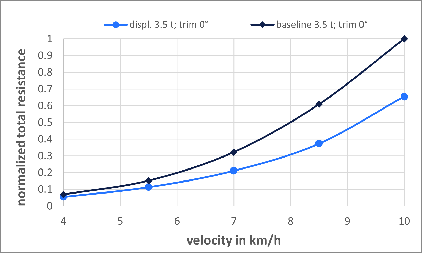
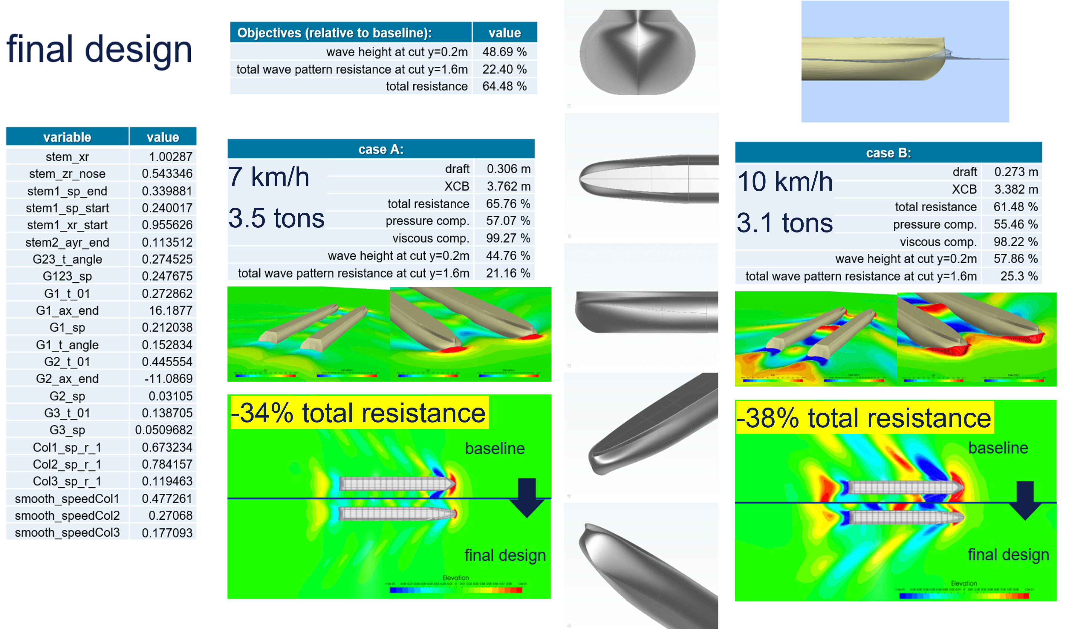
The best design variant shows a reduction in total resistance by 65.76 % of the baseline value for case A and by 55.92 % for case B. The improvement for the maximum wave height at y=0.2m is 44.76% for case A and 56.72 % for case B. The total wave pattern resistance at y=1.6m could be reduced the most, where the baseline values decreased to 21.16% for case A and 19.49% for case B. The figure below presents the resistance curves for the final design compared to the baseline Rollyboot with a displacement of 3.5 tons.
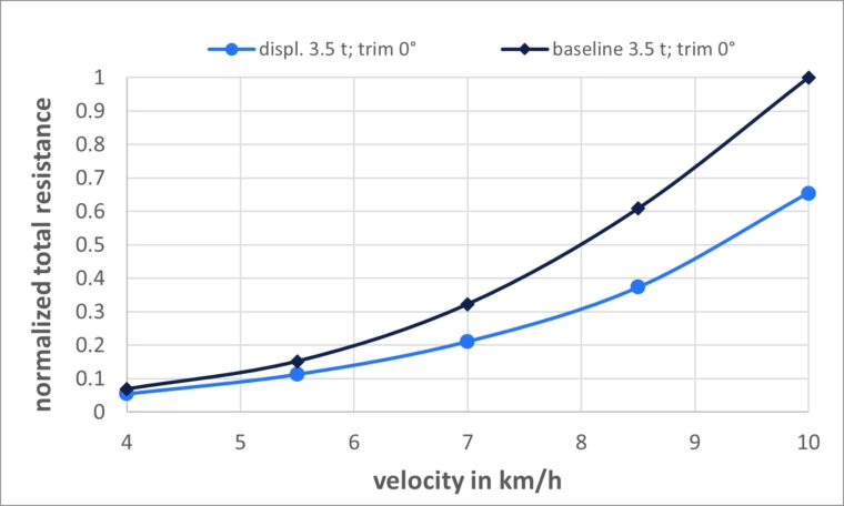
Resistance curves for best design and baseline design
The improved hull form will significantly extend the vessel’s range. The table below presents the results of an estimation conducted for case A (3.5 tons displacement and 7 km/h). While the increase in hours may seem modest, the potential distance increases significantly from 35 km to 47 km. This applies under the examined conditions and if the Rollyboot Evolution retains its 20,000 kW energy system.
| Range in h | Range in km | |
| Rollyboot Evolution (original) | 5 | 35 |
| Rollyboot Evolution with new bow | 6.7 | 47 |
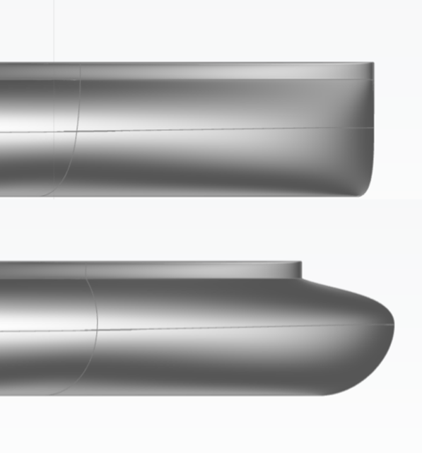
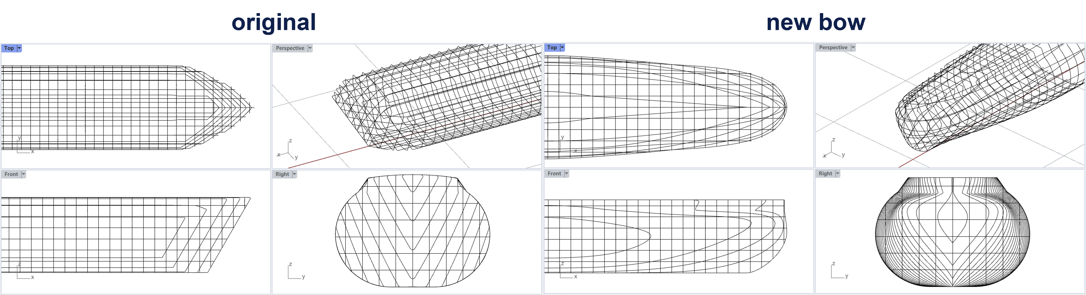
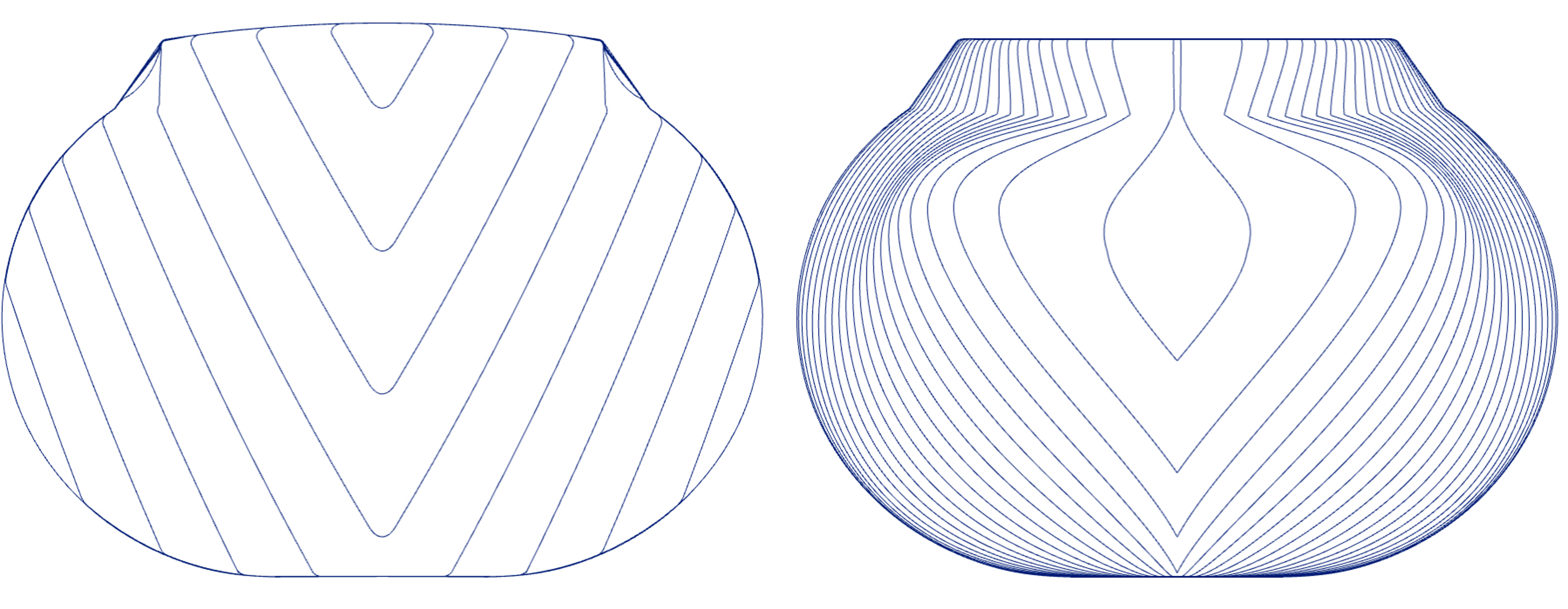
The following figures show the geometry of the new bow compared to the original design as well as an overview of the results for the final design.
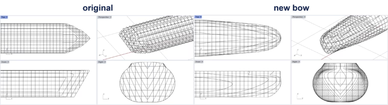
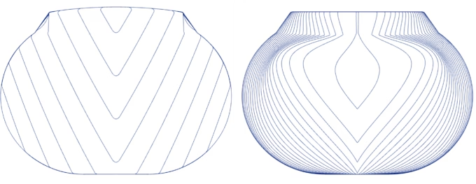
Hull lines from the original (left) and the best design with a new bow (right)
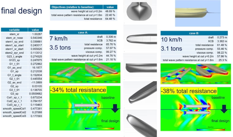
Results of the best design - overview of optimization objectives
Finally, the last illustration shows the newly designed module commissioned by Rollyboot.
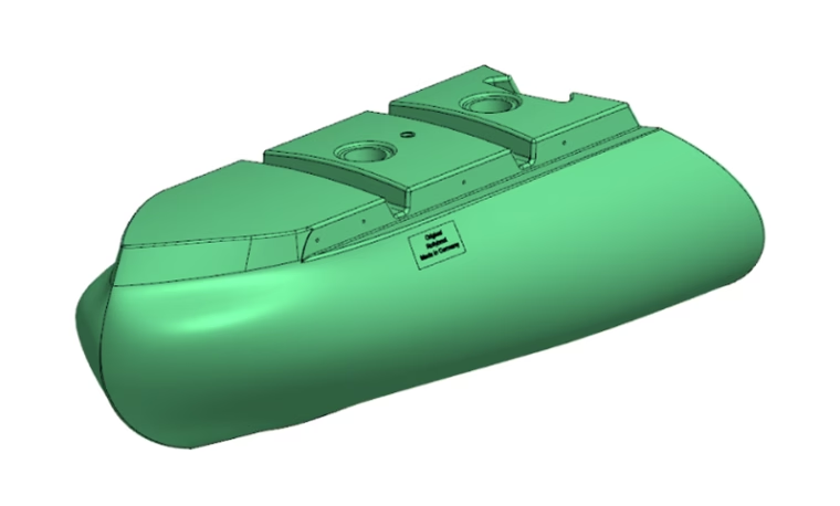
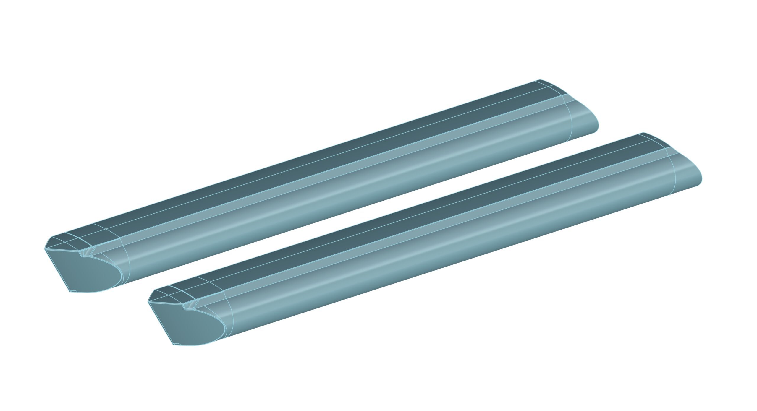
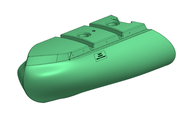
New bow module for the Rollyboot
Conclusion and Outlook
The study successfully identified an optimized hull form for the “Rollyboot Evolution”, achieving up to 34% reduction in total resistance at 7 km/h for a 3.5‑ton load and 38% for the transit case. The optimized design also showed reduced wave height and wave pattern resistance, making it well-suited for fully electric operation on inland waterways. Both the standard CAD model and the reduced-order KLE model, using NSGA-II as optimization method, delivered promising results. The KLE model shows strong potential for significant efficiency gains, where further computational resources and time would allow these benefits to be demonstrated more fully. Still, the KLE model effectively reduced the number of CAD design parameters from 23 to 7 principal parameters while maintaining 96.2% variability of the model.
Additional research should include hydrostatics, performance at lower speeds and shallow water, and potential improvements through stern redesign, asymmetric hulls, or modular extensions. Other relevant aspects such as propeller-hull interaction, tunnel clearance, and wave behavior between demihulls also warrant further exploration. Physical model testing is also suggested for validation.
The study establishes a foundation for exploring the resource-saving potential of applying a KLE model in NSGA-II and RANS-based optimization, with promising opportunities for validation through further comparisons between the KLE and CAD models under consistent conditions. Enhancing the KLE model quality and investigating single-objective optimization (e.g., using the Tangent Search method) could provide deeper insights.
About the Author
Fiona Schlote is a Project Engineer in the Ship Performance Center at DNV Maritime Advisory. She studied Naval Architecture and Ocean Engineering at Technische Universität Berlin and completed her master’s thesis in 2024 in collaboration with FRIENDSHIP SYSTEMS, Rollyboot, and DNV.
“My first introduction to CAESES came during a university lecture, where I was immediately fascinated by the possibilities of parametric modeling and optimization. This sparked a strong interest in learning more. While working as a student assistant at DNV, I was pleasantly surprised to discover that the company also used CAESES. This alignment gave me the opportunity to shape my master’s thesis around the software. Integrating DNV’s viscous flow solver and meshing tools with CAESES proved to be both intuitive and effective, demonstrating the software’s flexibility and interoperability.
Even now, I enjoy using CAESES in my daily engineering work and remain enthusiastic about its potential to streamline complex design processes.”
Fiona Schlote
Project Engineer