Design and Optimization of Ventricular Assist Devices
The design of ventricular assist devices is quite literally a matter close to our hearts. A ventricular assist device (or VAD) is an electromechanical pump for assisting cardiac circulation, which is used to partially replace the function of a weakened or failing heart. VADs are designed to assist either the right ventricle (RVAD) or the left ventricle (LVAD), or to assist both ventricles (BiVAD). Some are for short-term use, typically for patients recovering from myocardial infarction (heart attack) or cardiac surgery; some are for long-term use, typically for patients suffering from advanced congestive heart failure. Normally, the long-term VAD is used as a bridge-to-transplant — keeping the patient alive in reasonably good condition, while being able to await the heart transplant outside of the hospital. In some instances, however, VADs are also used as destination therapy, which is an alternative to heart transplant. Destination therapy provides long-term support in patients who are not candidates for transplant.
Ventricular Assist Devices: Pulsatile Pumps vs. Continuous Flow Pumps
The pumps used in ventricular assist devices can be divided into two main categories — pulsatile pumps that mimic the natural pulsing action of the heart, and continuous flow pumps. Pulsatile VADs use positive displacement pumps. Continuous-flow VADs are smaller and have proven to be more durable than pulsatile VADs. They normally use either a centrifugal pump or an axial flow pump.
Adverse Events
Thrombus formation, Acquired vonWillebrand Syndrome (AvWS), and hemolysis are frequent adverse events associated with ventricular assist devices. These events are primarily dependent on shear stress, strain rate, and turbulent energy dissipation in the fluid, which can be approximated based on the velocity fields obtained from experimental flow visualization or computational fluid dynamics (CFD). Through manipulating and optimizing the device’s components, such as the rotor and casing geometries, these properties can be altered and controlled in such ways as to minimize the adverse events mentioned above.
Example Case: Ventricular Assist Device Design with CONVERGE

This example case is part of an ongoing project carried out in the Division of Applied Biomedical Engineering at the Penn State College of Medicine. The subject of the study is a centrifugal pump intended for right heart support (RVAD), and more specifically – in this first step – its impeller. The goal is to create a flexible parametric model for the impeller in CAESES® to be able to quickly and easily create design variants that, in connection to the CFD solver CONVERGE CFD, are used to predict pump performance curves (HQ) or for CFD-driven optimization aimed at reducing the turbulent energy dissipation (EPS) and recirculation regions in the pump.
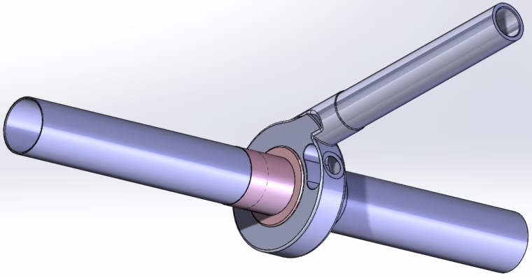
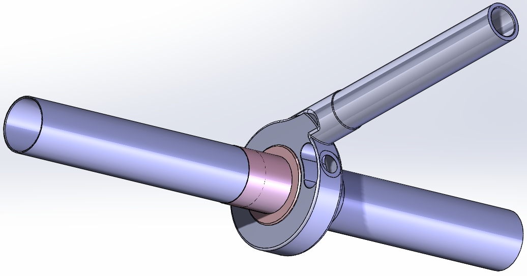
View of the complete ventricular assist device assembly
Geometry Setup
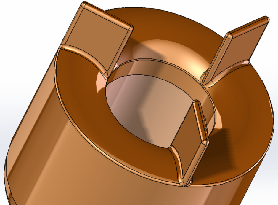
The baseline geometry of the impeller had previously been designed in SOLIDWORKS and consisted of a toroidal rotor body, necessary for the magnetic drive, and three straight vertical blades that are superior facing, while in vivo. While this simple design may seem crude, it proved to be relatively blood-friendly in preliminary trials, when compared to other potential solutions, such as foil-shaped blades.
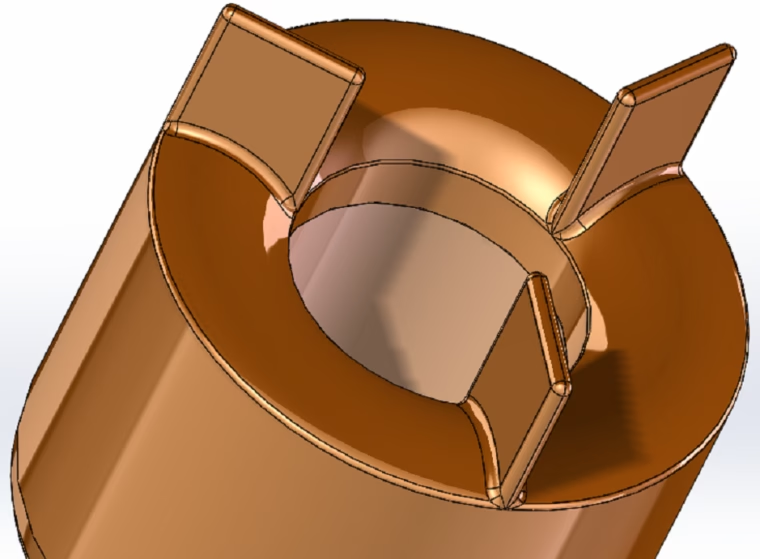
Original impeller of the ventricular assist device, as modeled in SOLIDWORKS
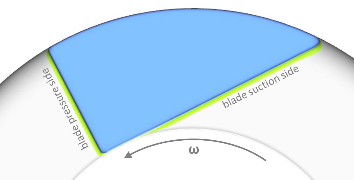
To further evolve this initial design, it was decided to add a fairing – basically, a wedge – on the suction side of the blades in the parametric CAESES® model. The suction side is of great interest, as it is believed to dictate both the magnitude and shape of the recirculation region behind the blade, as well as the surface effects on the rotor surface.
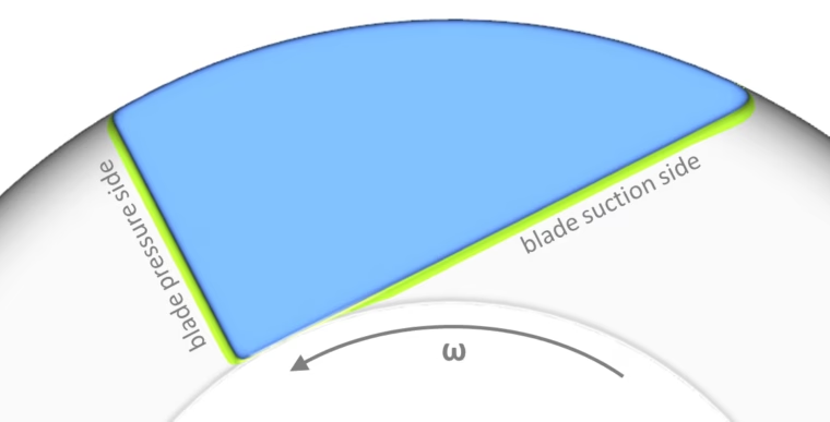
Blade shape of ventricular assist device, modeled in CAESES with sense of rotation
The inner surface of the suction side fairing is modeled with a B‑Spline curve that allows for a flexible variation of its shape, under control of a few dedicated parameters. Additional geometry parameters control the size of the blades in radial and circumferential direction, the fillet radii on the corners of the geometry, and the number of blades.
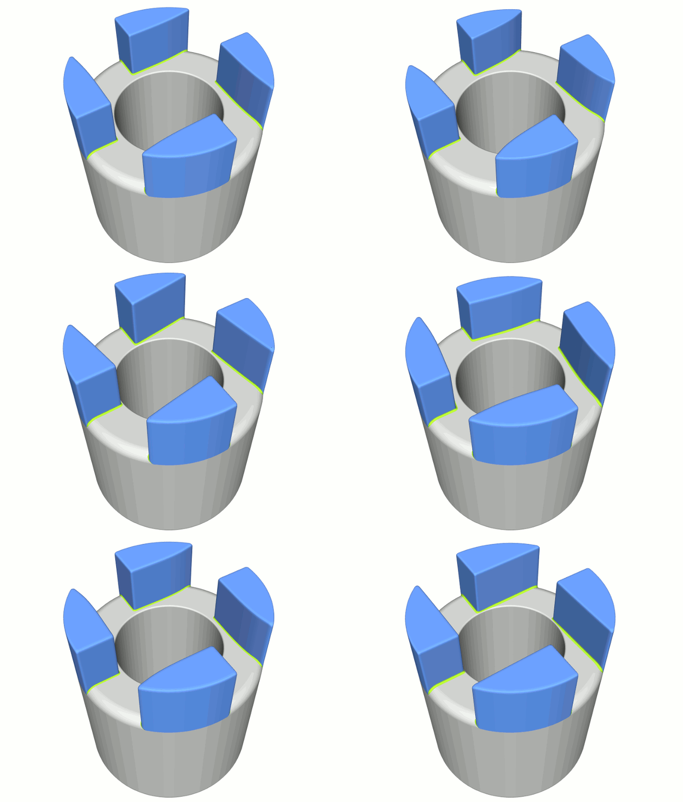
Automated variation of the blade shape parameters
CONVERGE Automation
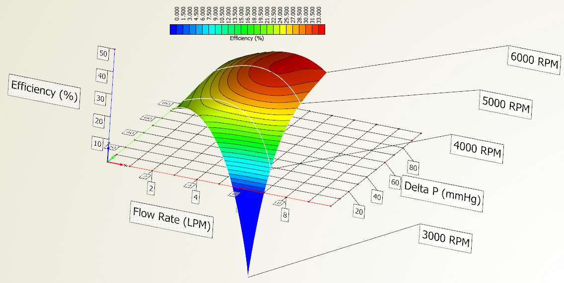
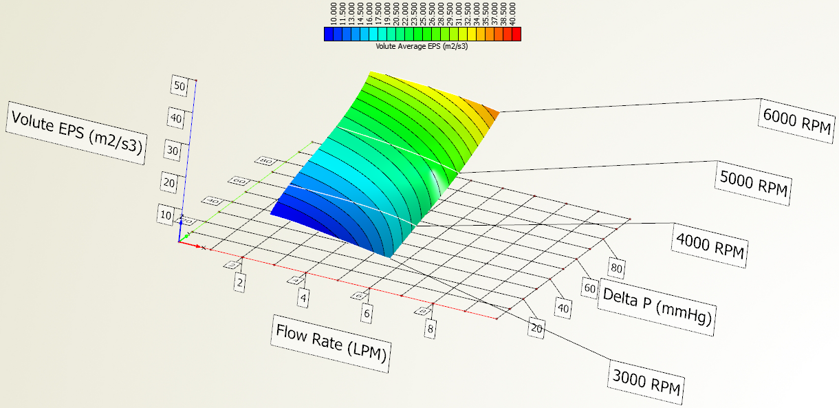
The impeller geometry, as well as the other parts of the pump’s fluid domain, that had previously been imported in CAESES®, are exported to CONVERGE CFD in its proprietary, tessellated “surface.dat” format that allows to identify surface patches by their color and boundary ID. This is needed for being able to replace the geometry in the optimization process, while keeping the associativity and automatically assigning the correct boundary settings. Furthermore, distinguishing different boundaries also allows for more localized predictions of values such as EPS and strain rate. Simulation control can be administered through CAESES® using the CONVERGE CFD input files in the Software Connector. The boundary conditions of the blood pump (such as inlet flow rates, outlet pressure, and rotor speed), simulation parameters (such as simulation end time, time step sizes, and grid size), and computational power (the number of cores used) can all be turned into parameters, allowing the user to adjust and run new CONVERGE CFD simulations – manually or automatically – without the need for opening the CONVERGE CFD interface. Pump performance prediction consists of creating HQ (pressure head vs. flow) curves for a given pump and rotor configuration. The Design Assembler engine in CAESES® (that allows the user to prescribe specific combinations of values) was used to conduct the HQ simulations, allowing for multiple flow rates and speeds to be tested efficiently in an automated fashion. The efficiency and volute region averaged EPS can be plotted along with the standard HQ curves to create 3D plots that allow for a more comprehensive performance evaluation.
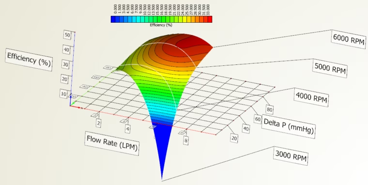
HQ surface plot for efficiency
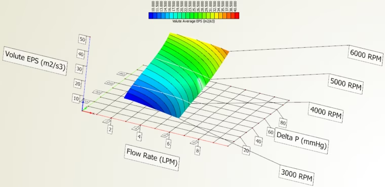
HQ surface plot for volute average EPS
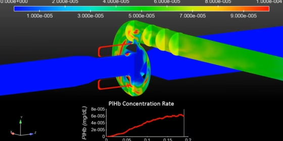
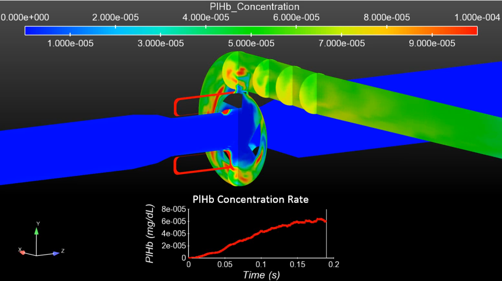
The results show that the HQ vs. efficiency surface is convex in nature, and appears to have at least a local maximum for efficiency (if not an absolute maximum). Running more conditions at higher speeds could reveal if the most efficient range has already been discovered. The HQ vs. volute average EPS surface has a positive slope predominantly in the speed and delta P directions, and therefore a stronger dependency from these quantities. While there also is a dependency from the flow rate, it is less pronounced. The following picture shows cross-sectional planes of the inlets/outlet of the pump which show the presence of PlHb (plasma free hemoglobin) as the simulation runs. PlHb levels increase with the presence of hemolysis, and it is calculated based on the turbulent energy dissipation user-defined function in CONVERGE CFD.
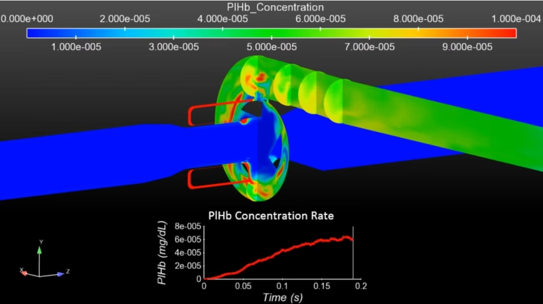
Visualization of PlHb (plasma free hemoglobin) concentration
Optimization Process and Results
Exploratory studies on the rotor design parameters were conducted using both the Design Assembler and a Latin Hypercube Sampling. As a very broad approach meant to find the functional domain of the design parameters, the Design Assembler can be used first to set larger intervals for the parameters to be tested, before refining the parameter domains, in order to be computationally efficient with limited resources. This was followed up with a DoE (Design of Experiments) process using a Latin Hypercube Sampling method that provides a proper sensitivity analysis within the refined range of the design parameters. Finally, a local optimization was started in a promising region of the design space, as identified by the previous DoE process.
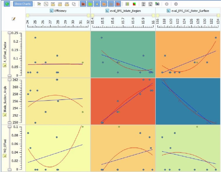

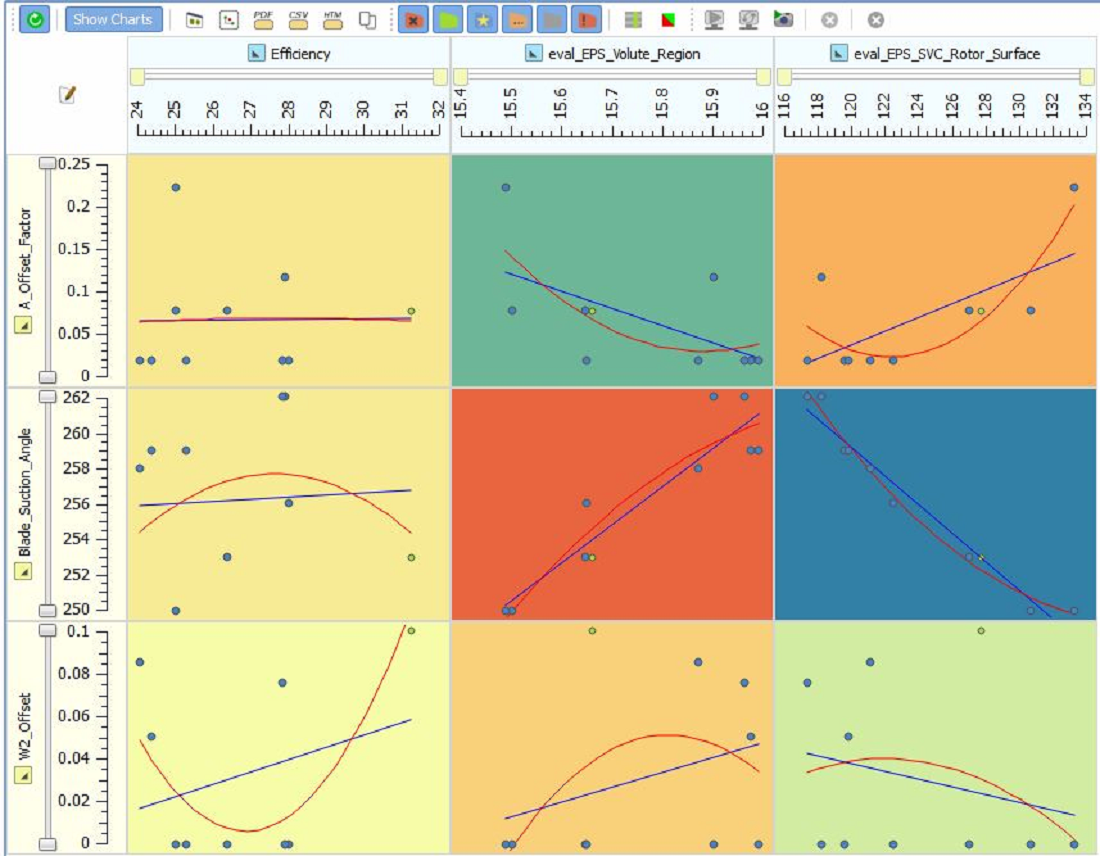
Correlation plots for design variables and objective values
The data collected from the DoE studies has revealed the correlations of the considered rotor parameters to the EPS, which will help to drive future optimizations. Here, the length of the fairing behind the blades seemed to have the most recognizable trend with the volute average EPS evaluation. The effects on the rotor surface EPS evaluation would be interesting to discover in more detail, as both EPS evaluations appear to be inversely related. Continuing to uncover the effects of the suction side geometry on EPS, the local optimization results show the same well visible relationship between the fairing length and both EPS evaluations, and the offset from the inner blade corner to the central hole of the toroidal rotor body seems to show a relationship as well. However, this first optimization was only run with 10 designs so these relationships will be more comprehensively understood once more data is collected.
Outlook
While the investigations so far had been carried out on local resources of the Division of Applied Biomedical Engineering, future studies will move to the High Performance Computing center of the Penn State College of Medicine. With the increase in computational power, the plan is to conduct more extensive optimizations, including additional geometry variables, as well as more expensive evaluations, involving longer solve times, smaller grids sizes and LES computations, using a user defined EPS-based hemolysis model, as well as a strain rate based model for thrombus susceptibility potential. Also, additional components of the RVAD are going to be parameterized and considered in the optimization studies, such as – most prominently – the volute casing.
CAESES’ VAD Design Capabilities
CAESES® is being used to design state-of-the-art VADs and brings along several key capabilities for this task.
- CAESES® contains DoE/optimization algorithms, workflow management, interfaces to external simulation codes and a highly specialized parametric CAD system. All of which are critical components for setting up an automated design process.
- Robust variation of the VAD geometry is possible with no failed variants. As for other geometries, one of the most important targets of our software is 100% robust geometry variation, obtained by smart parameterization and dependency-based models.
- CAESES®’ powerful Meta Surface technology – were a parameterized cross-section is swept in a specified direction, e.g., along a path, and function curves control how the cross-section parameters change during the sweep – allows for a highly flexible, while very efficient, parametric description of complex, free-formed, shapes (such as impeller blades or volutes).
- Arbitrary constraints can be built into the model or monitored. Typical examples are manufacturing or packaging constraints.
- The geometry can be exported in several different formats suitable for your CFD/meshing tools. Many of the formats support patch naming, so that the downstream tool can correctly identify surface patches for the assignment of individual mesh settings or boundary conditions.
Follow Us
If you are interested in CAESES® and in CFD-driven design optimization, then sign up for our newsletter. Don’t worry, we won’t bother you with too many emails. Of course, you can unsubscribe at any time :-)