CONVERGE CFD Software: Full Automation with CAESES
With CAESES version 4.4.2, we introduced a set of new features to automate the CFD software CONVERGE for the purpose of conducting design explorations and shape optimization. In recent posts about CONVERGE-related topics, we already talked about some of the existing features in CAESES and about some applications in more detail, such as piston bowl optimization.
This short article gives you an update on the existing CAESES capabilities and their function in the context of using CONVERGE as your CFD software.
Identifiers for Boundaries in CONVERGE Setups
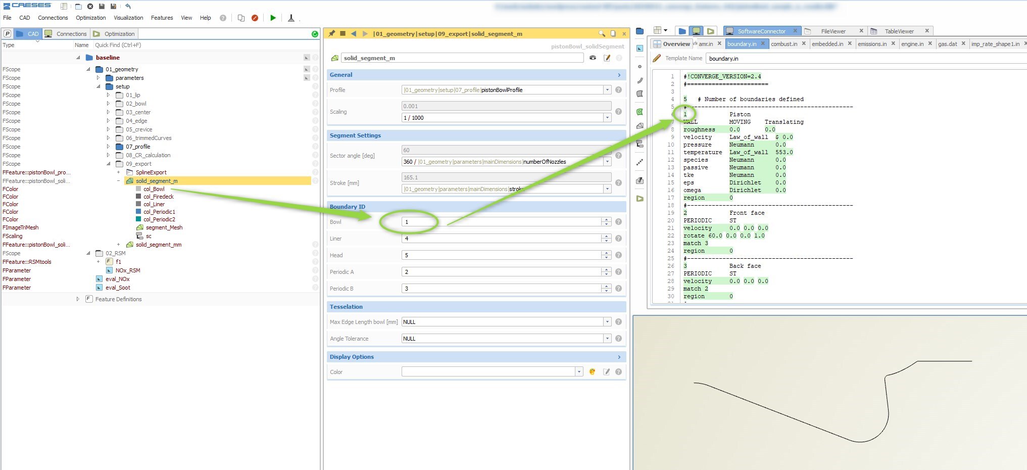
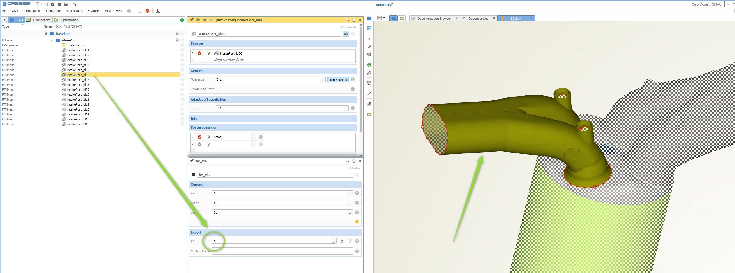
The CONVERGE setups contain identifiers (IDs) for the different boundaries of a geometry. These numbers are referenced at different locations in different CONVERGE input files. CAESES allows users to assign such an ID to a color, and then use this color during the geometry modeling process. This makes sure that the IDs of the CAESES geometry are always identical to the ones in the CONVERGE setup, even during automated design variations.
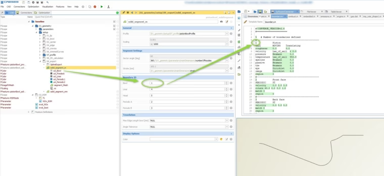
Custom boundary colors with IDs in CAESES, as given in the CONVERGE input file
Since CAESES also allows users to automate CFD runs using the software connector, everything is then immediately ready for quick studies with the integrated optimization strategies.
CONVERGE File Import
CAESES 4.4.2 comes with a new import for CONVERGE *.dat files. These geometry files contain the different boundary IDs, from which CAESES automatically creates colors. These colors are assigned to the imported geometry and hence give the different patches their IDs.
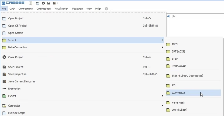
CONVERGE import to load *.dat files into CAESES
Users can then quickly replace the geometry parts that need variation or optimization. All file dependencies are preserved in this process, when using the colors and their IDs for the patches. The automatic color creation and assignment massively accelerates the optimization workflow and removes any manual interaction.
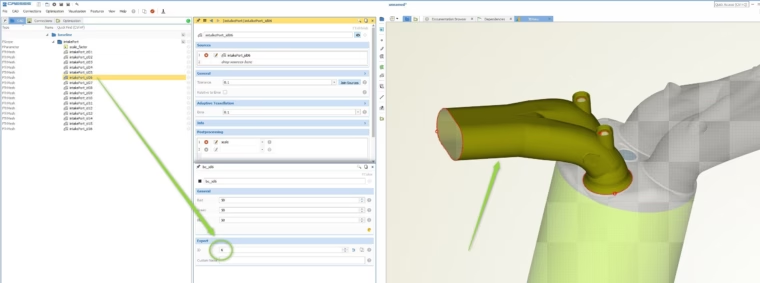
After importing the CONVERGE *.dat file, a color is assigned to the surfaces along with a color ID that is taken from the file
In addition to the colors and IDs, a scaling parameter is created to scale the geometry up and down according to the units that are needed, e.g., meters or millimeters.
CONVERGE File Export
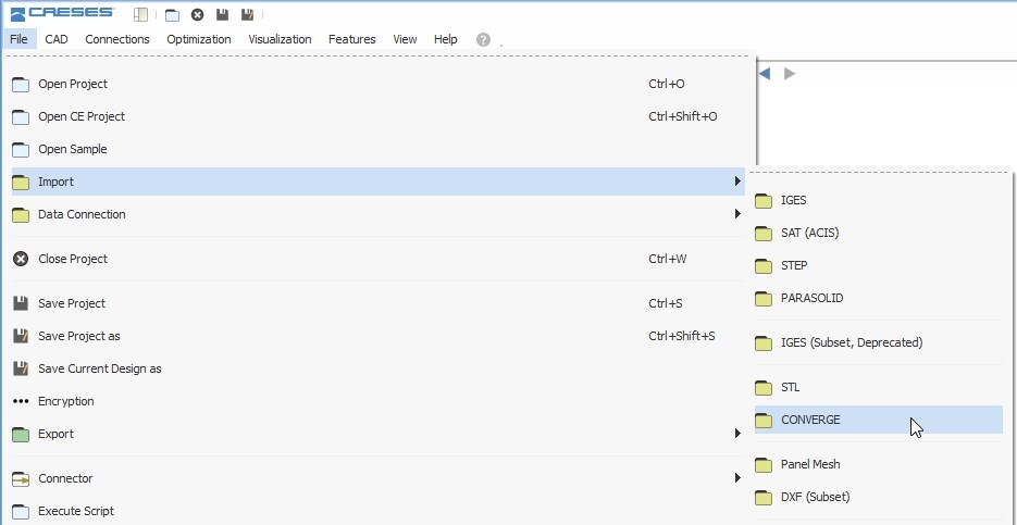
Once the faces are colored and hold a unique ID, users can export the geometry using the CONVERGE export in CAESES. During this export, the geometry is checked in terms of its face normal vectors. If they point to the outside of the geometry, there will be an automated correction to let all normal vectors point inward. The export can be found in the menu > file > export > CONVERGE.
Triangulation Controls
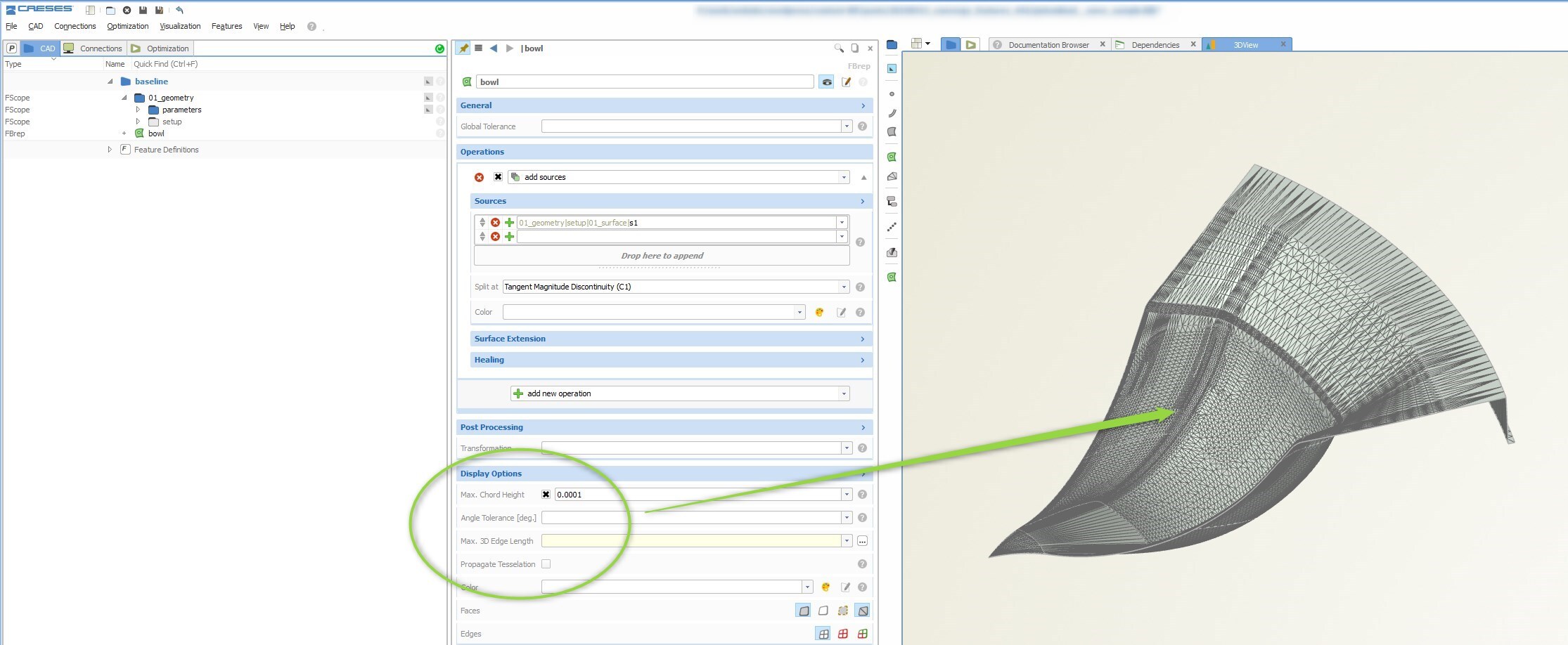
CAESES lets you create parametric models based on curves and surfaces. CONVERGE users can then control the triangulation of the final shape using the trimesh (i.e., the triangulated geometry) and BRep controls. The accuracy or the maximum edge length can be optionally set to prepare the triangulation for the CONVERGE analysis. These settings are retained for each design candidate during automated studies.
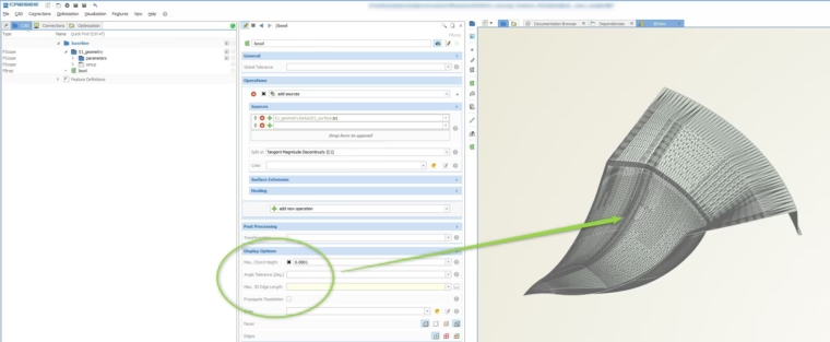
Triangulation controls for the geometry
Translate Boundaries
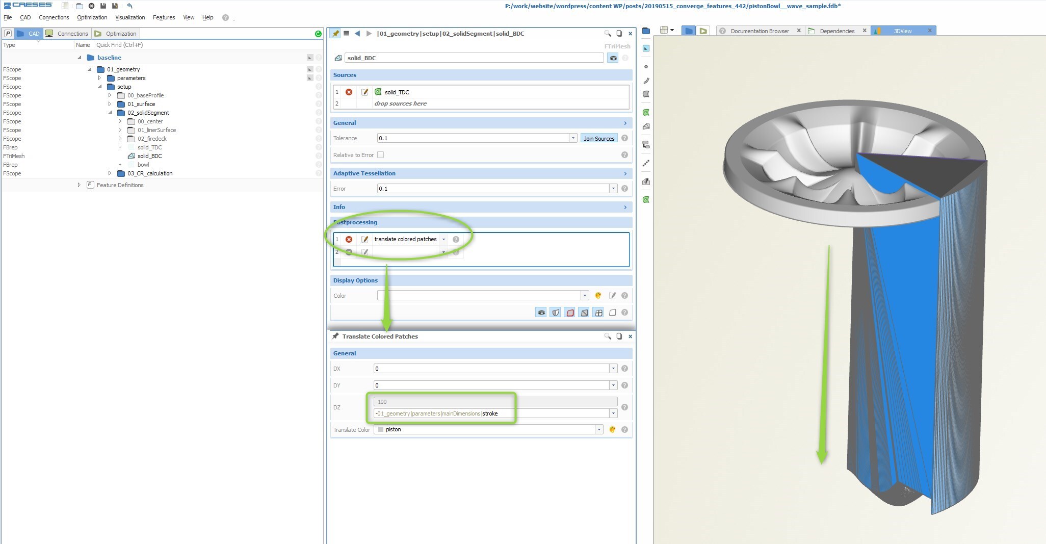
In some situations, such as the consideration of different piston positions, CAESES users can take one part of the full geometry and translate it, e.g., up or down, to another location without changing the general structure of the triangulation (i.e. the number of triangles and their connectivity). There is a new operation in the trimesh object that translates all patches that hold a specified color.
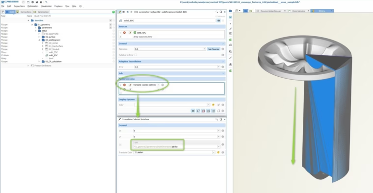
Translation of colored patches without changing the triangulation structure
This translation capability is important since CONVERGE internally moves the piston geometry up or down for the analysis. In order to avoid intersecting triangles, the CAESES geometry is typically modeled at the top dead center, and translated down to the bottom dead center before exporting it.
Geometry Modeling
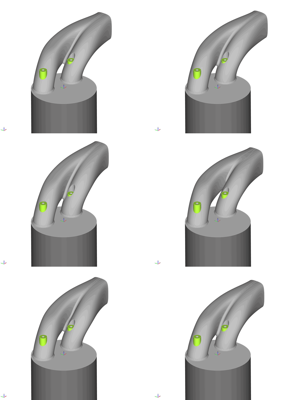
Aside from IDs, file handling and CONVERGE automation, there are also geometry modeling capabilities that address the CONVERGE user group. There are new tutorials for piston bowl and port modeling, as well as dedicated features to speed up the modeling process, e.g., to create a fillet between components such as the intake port. The following animation shows the results of a geometry study where this fillet is applied without manual interaction:
More Information
There is a webinar recording about CAESES and CONVERGE that gives a more comprehensive introduction to the coupling of these two software packages.
Check out the blog post about the CONVERGE export of CAESES for more information about coloring, IDs and CONVERGE setup files.
If you are interested in piston bowl design, then check out this piston bowl optimization blog post, which also comes with linking CONVERGE to CAESES.