Aviation propeller design and optimization: from geometry to real-world performance
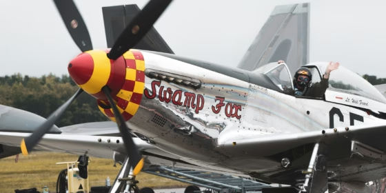
Designing an efficient aviation propeller is far more complex than it first appears. What seems like a simple rotating component quickly turns into a highly sensitive engineering challenge, where aerodynamics, structural constraints, and performance requirements are tightly interconnected. Even small geometric adjustments can significantly influence thrust, efficiency, noise, or vibration behavior.
Despite this complexity, many design workflows still rely on repetitive, manual steps – rebuilding geometry, rerunning simulations, and retracing paths that have already been explored. This not only slows down development but also limits how thoroughly designers can investigate alternative concepts. A more integrated, parametric approach offers a clear advantage by connecting geometry, simulation, and optimization into a continuous workflow.
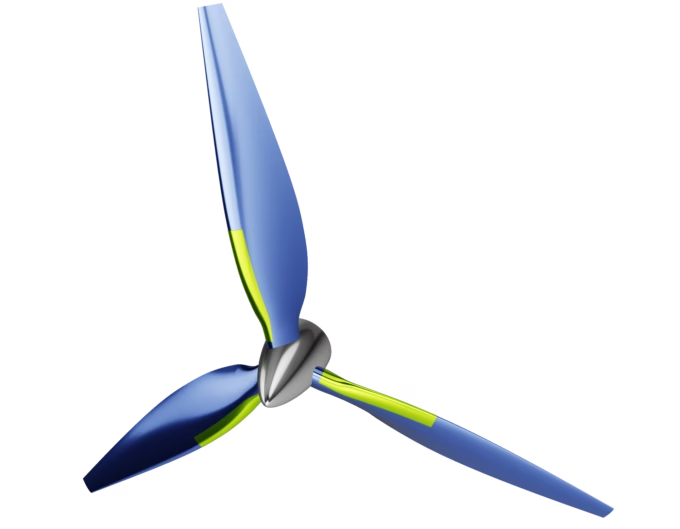
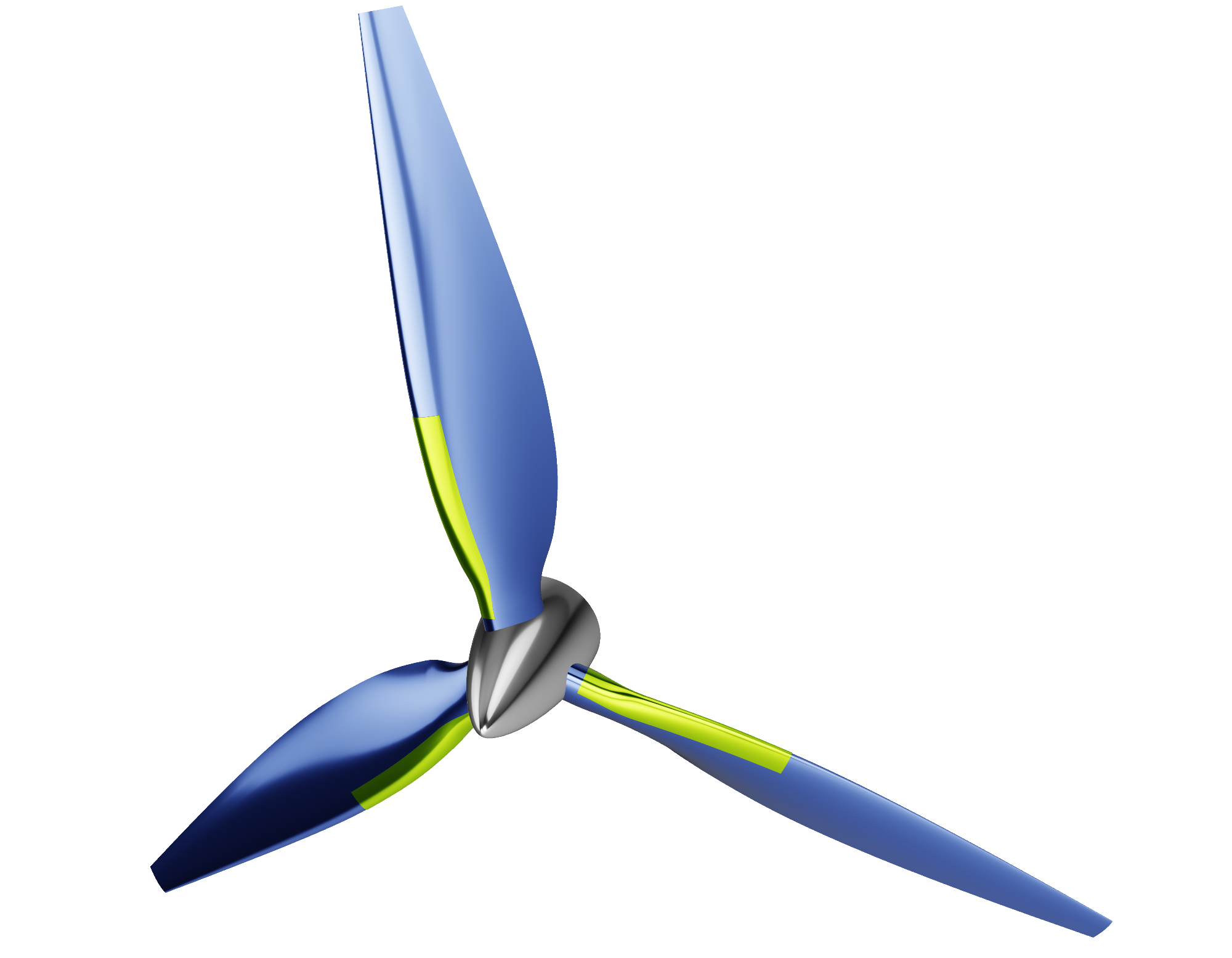
Variable-pitch propeller with anti-icing leading edges
Why aviation propellers are so challenging
Although aviation and marine propellers share similar principles, operating in air introduces very different physical challenges. At higher rotational speeds, compressibility effects become relevant, and parts of the flow can enter transonic regimes, potentially causing shock waves and efficiency losses. In addition, performance is highly sensitive to Reynolds number variations along the blade.
Unlike marine applications, where cavitation is a primary concern, aviation propellers must meet strict requirements for noise and vibration. These constraints, combined with changing flow conditions along the blade radius, result in a system where every geometric detail matters, and simplifications can quickly lead to suboptimal designs.
Moving beyond manual geometry
Traditional propeller design workflows often involve direct manipulation of geometry – adjusting surfaces, exporting models, repairing issues, and repeating the process. While this approach can work for simple iterations, it becomes increasingly inefficient as complexity grows.
A parametric modeling strategy fundamentally changes how geometry is handled. Instead of editing shapes directly, the designer defines relationships that govern how the propeller is constructed. Parameters such as chord length, pitch angle, thickness distribution, and blade curvature are described mathematically and linked together.
This means that when a single parameter is adjusted, the entire geometry updates automatically and consistently. There is no need to rebuild the model or fix broken surfaces. The propeller remains simulation-ready at all times, allowing for rapid iteration and exploration.
More importantly, this approach encourages a deeper understanding of the design itself. Rather than focusing on isolated geometry tweaks, engineers can think in terms of cause and effect – how changing a distribution or parameter influences overall performance.
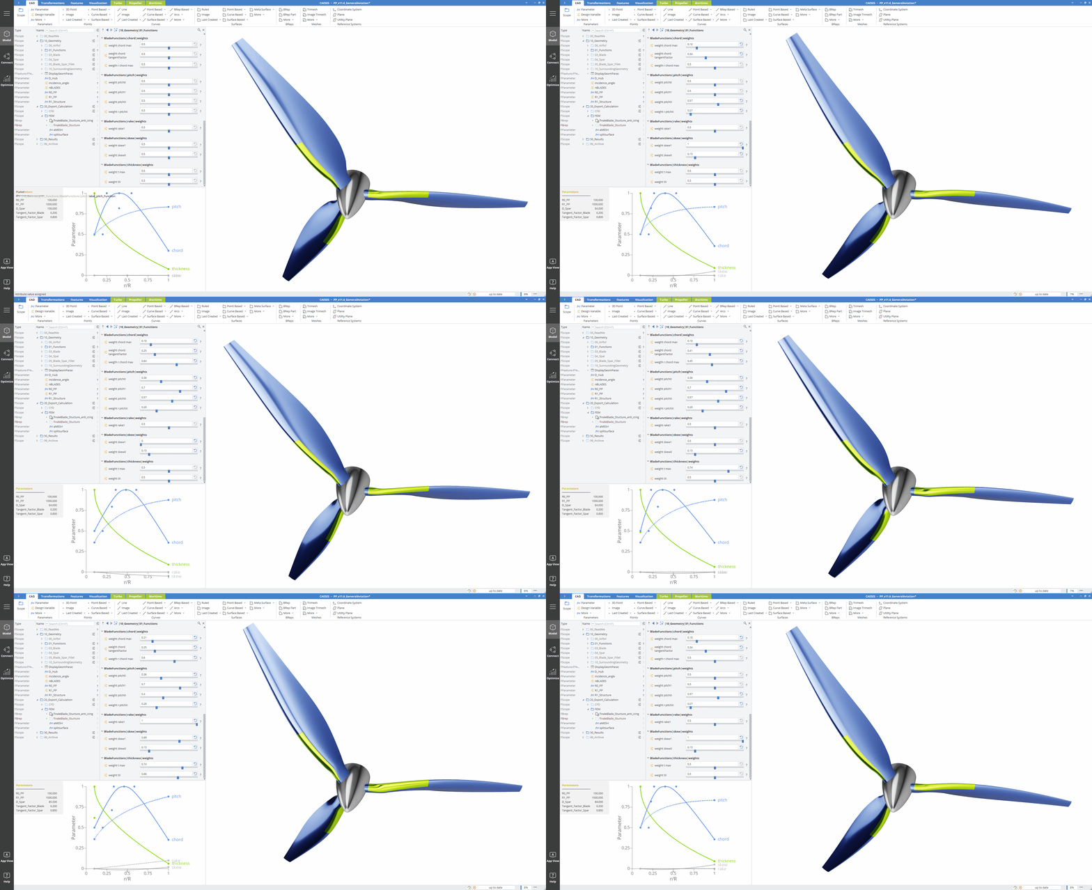
Propeller Variation
One workflow, different propeller concepts
Aviation propellers come in many forms, from simple fixed-pitch designs to more advanced variable-pitch systems. While the underlying physics remains consistent, the design priorities and trade-offs can differ significantly depending on the application.
Fixed-pitch propellers are valued for their simplicity, low weight, and reliability. They are commonly used in unmanned aerial vehicles, ultralight aircraft, and training platforms where robustness and ease of use are essential. However, their performance is inherently limited to a narrow operating range.
Variable-pitch propellers, on the other hand, introduce additional flexibility by allowing the blade angle to change during flight. This enables better performance across different phases such as takeoff, climb, and cruise. The added complexity, however, requires more careful design and integration.
A parametric workflow makes it possible to explore both concepts within the same overall framework. Designers can even switch between configurations, compare performance, and evaluate trade-offs without starting from scratch each time. This significantly reduces development time and opens the door to more comprehensive design studies.
From fast estimates to high-fidelity analysis
Simulation plays a central role in propeller design, but not all methods are equally suited for every stage of development. High-fidelity CFD provides detailed insights, but it is too time-consuming for early-stage exploration.
This is where faster methods, such as blade element models, become valuable. These methods provide quick estimates of key performance metrics like thrust, torque, and power consumption. While less detailed than CFD, they are invaluable for screening concepts and identifying promising directions.
By combining fast, approximate methods with selective use of high-fidelity simulations, engineers can strike a balance between speed and accuracy. This layered approach ensures that computational resources are used where they provide the most value.
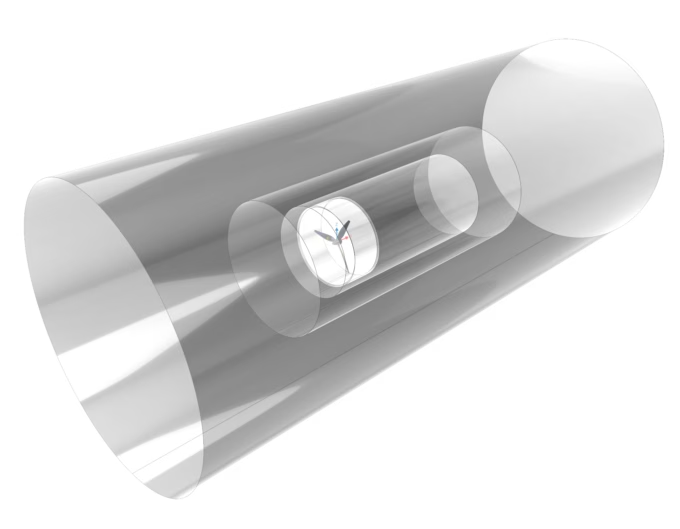
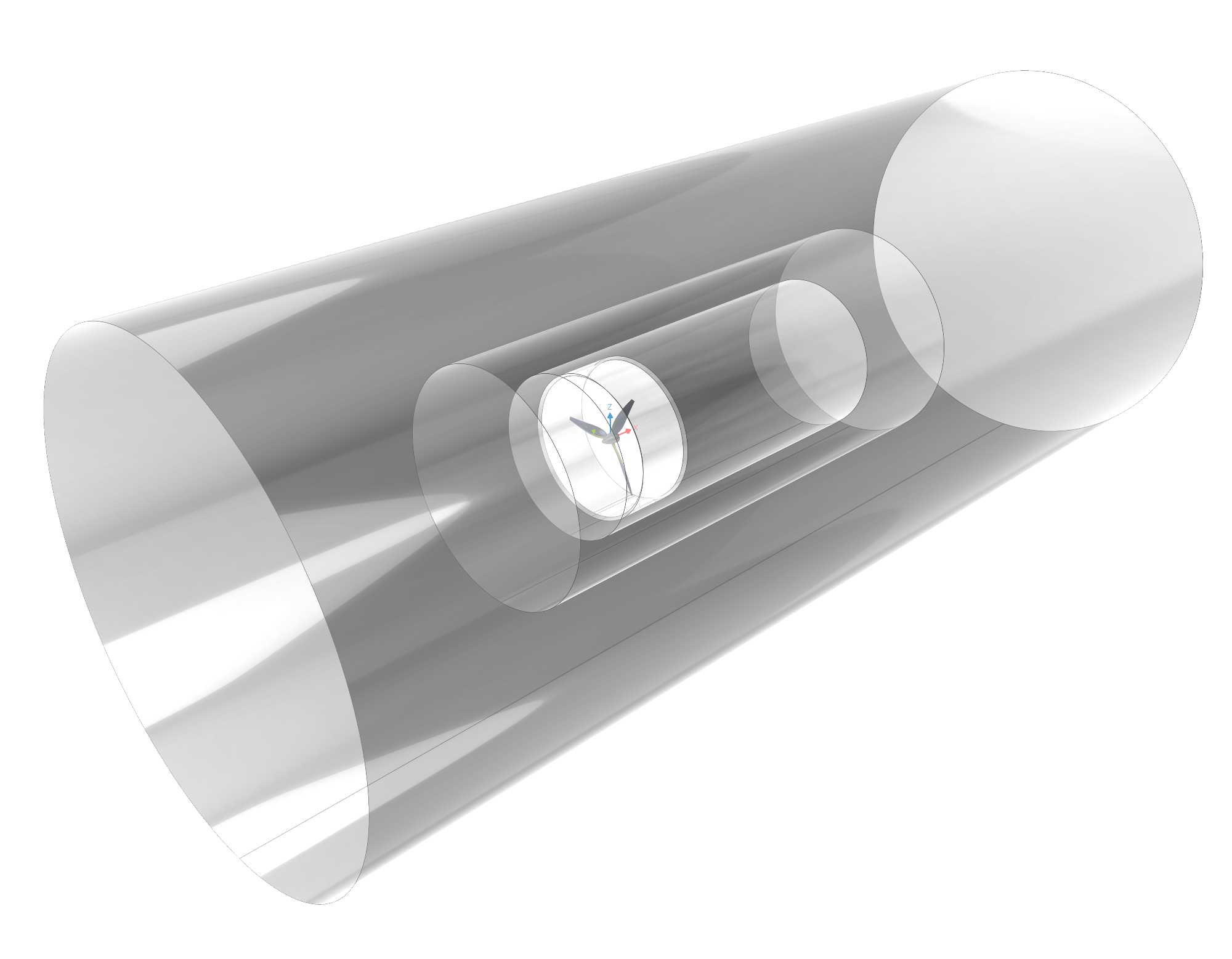
Propeller with CFD domain
Integrating simulation into the process
No matter which tool is used at the respective stage of the process, an integrated workflow truly proves its worth. Instead of manually preparing simulation models, engineers can automate the generation of computational domains, mesh refinement regions, and solver setups.
This not only reduces preparation time but also improves consistency and reproducibility. It even allows designers to expand the scope of their analysis beyond the propeller itself.
In real-world applications, a propeller does not operate in isolation. The surrounding aircraft geometry – fuselage, cockpit, landing gear, and structural components – affects the airflow and, ultimately, the propeller’s performance. Ignoring these interactions can lead to misleading conclusions.
An integrated approach makes it feasible to include these effects in the simulation process, leading to more realistic and reliable results.
A real-Life example: the “Libelle” human-powered aircraft
The importance of system-level thinking becomes particularly clear in innovative projects such as the “Libelle” human-powered aircraft developed by the student team Odonata e.V. in an effort to break the world record for the longest distance flight under human power. In such an extreme design scenario, efficiency margins are incredibly tight, and even small aerodynamic interactions can have a noticeable impact.
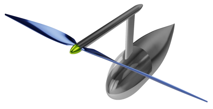
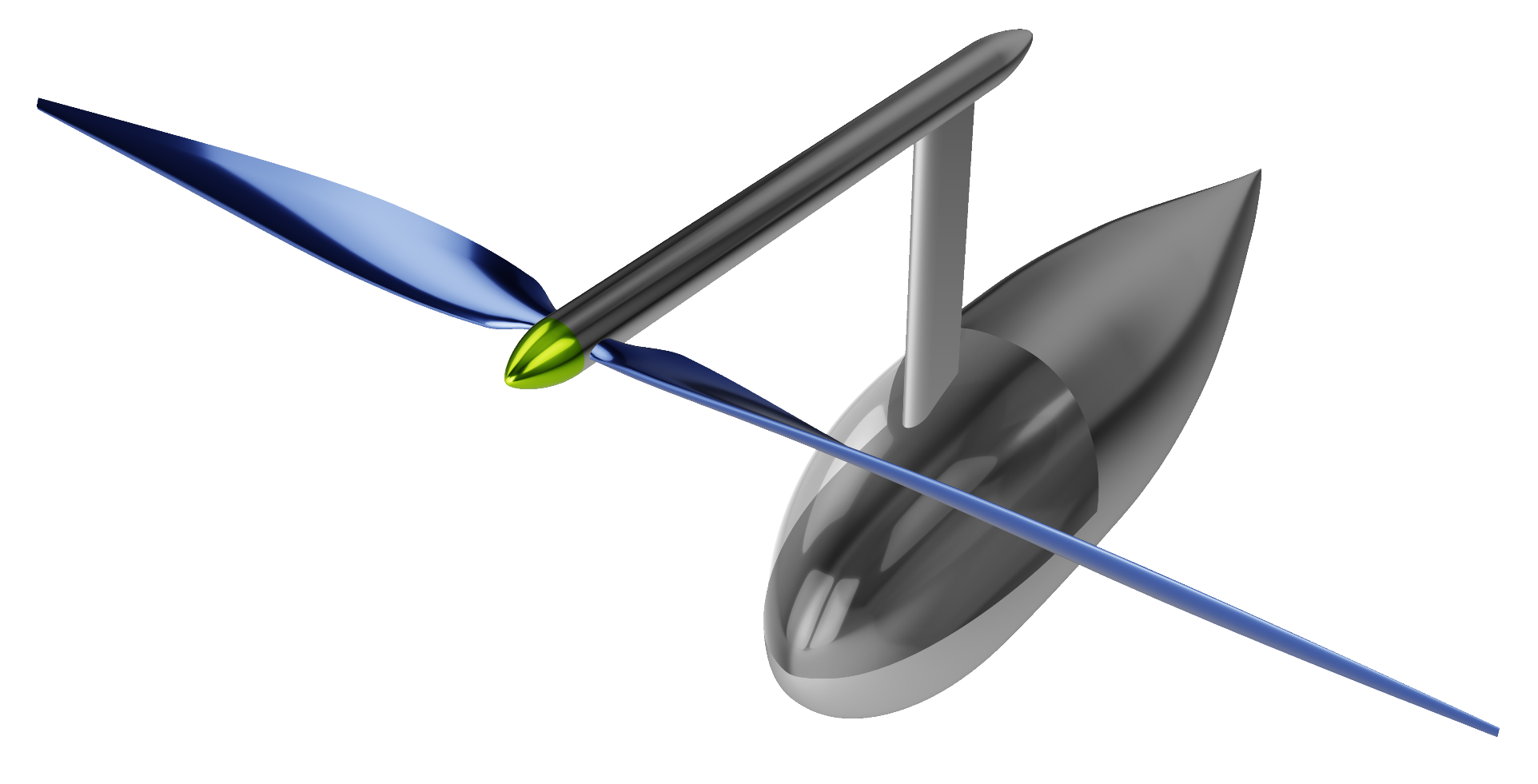
Human-powered aircraft propeller with surrounding geometry
Rather than optimizing the propeller in isolation, the development team considered the entire aircraft as a coupled system. By integrating the cockpit and supporting structures into their analysis, they were able to capture interference effects that would otherwise have been overlooked.
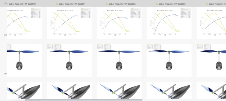
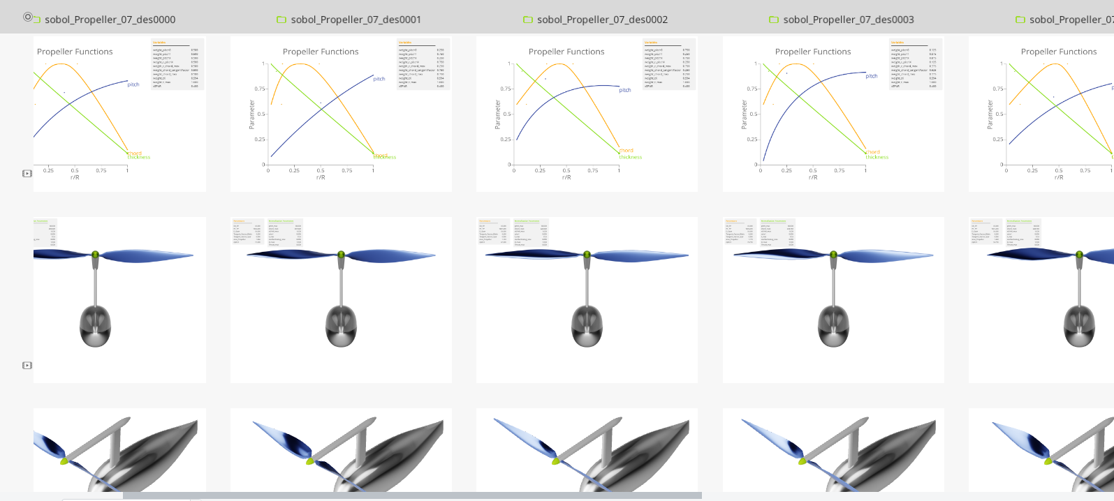
Variant Comparison
This holistic approach enabled them to better understand how airflow behaves around the aircraft, reduce performance losses caused by interactions, and compare multiple design options under realistic conditions. The result was not just a better propeller but a more optimized overall system.
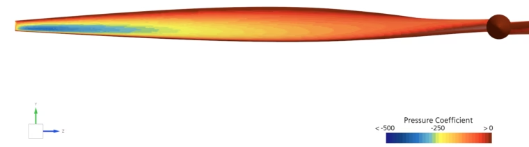
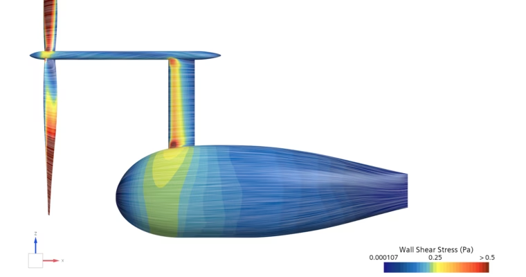
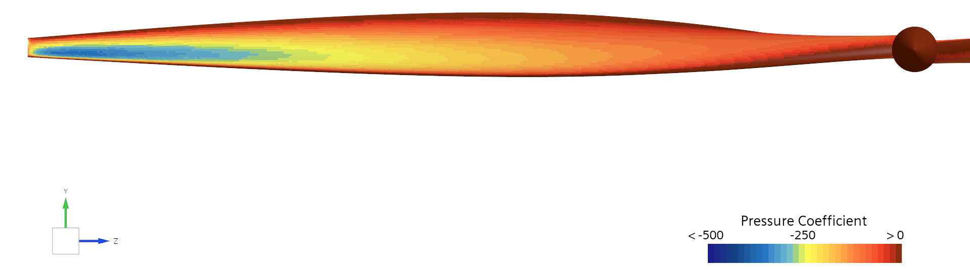
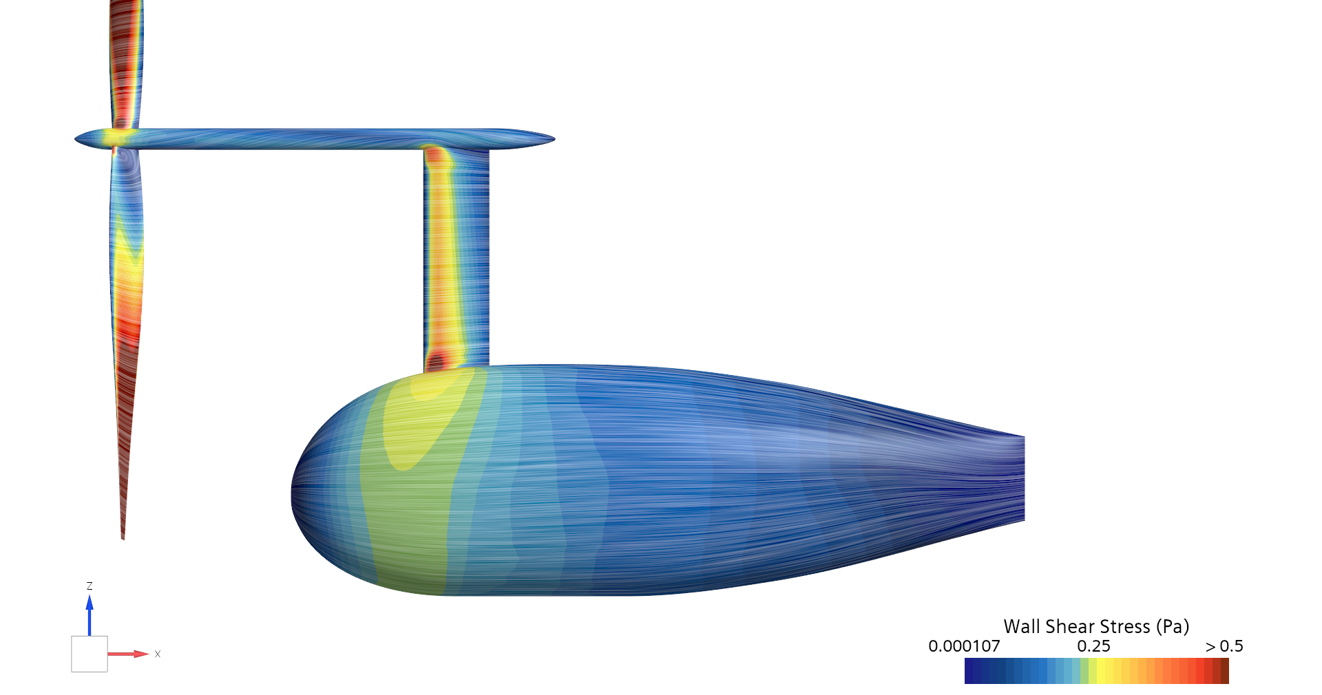
Pressure distribution on the propeller (top) and wall shear stress on the aircraft body and pylon (bottom)
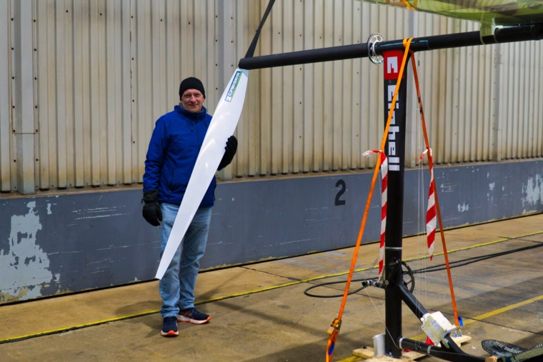
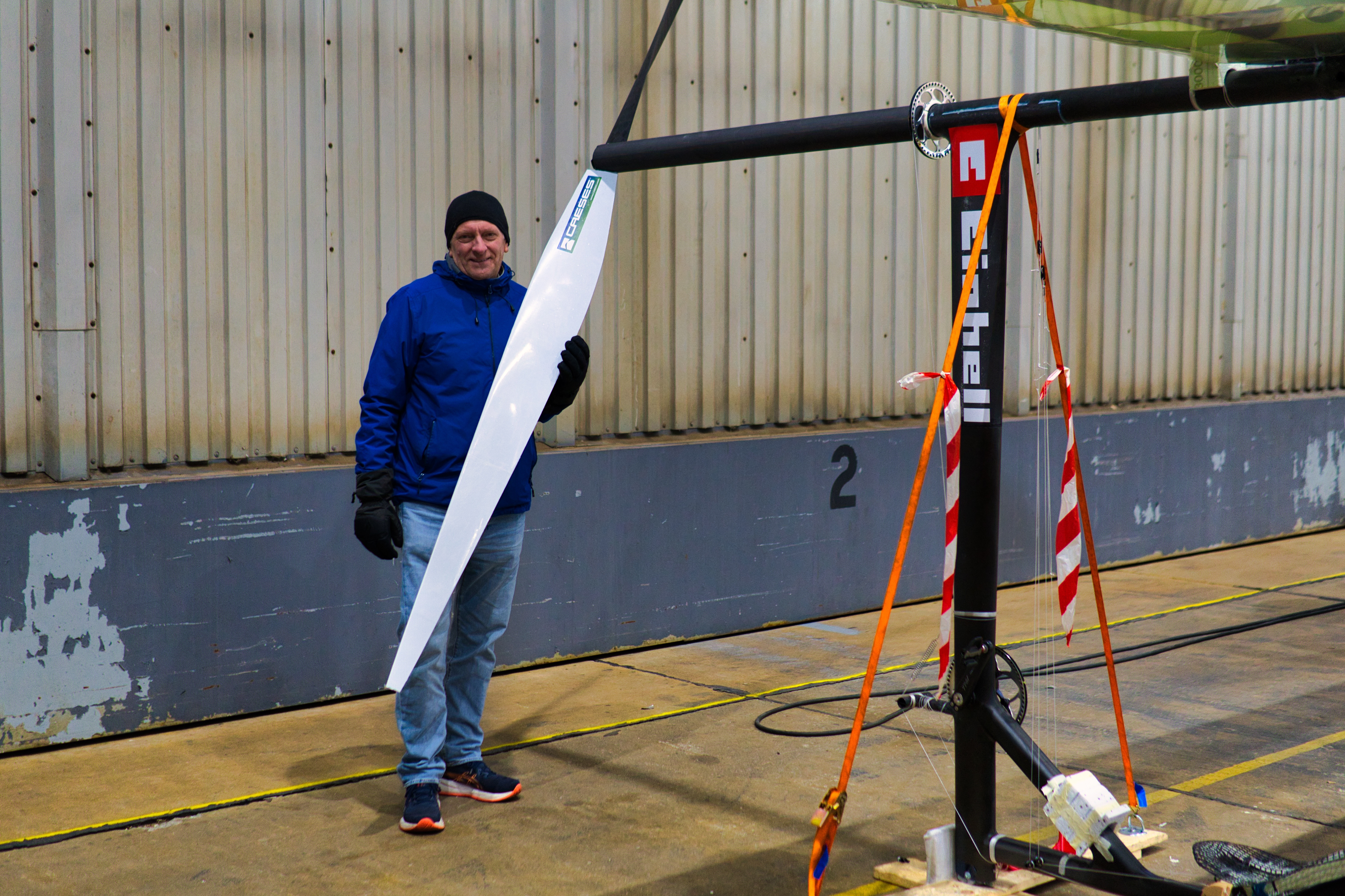
Manufactured propeller for “Libelle” with a happy FRIENDSHIP SYSTEMS CEO 😉
What are we actually optimizing for?
At its core, propeller design is an exercise in balancing competing objectives. Improving one aspect of performance often comes at the expense of another, and there is rarely a single “perfect” solution.
Designers must consider efficiency across a range of operating conditions, not just a single design point. They need to ensure that sufficient thrust is generated while keeping torque and structural loads within acceptable limits. At the same time, noise and vibration must be minimized, and weight should be kept as low as possible.
These competing requirements make it essential to adopt an iterative and flexible design process. Rather than searching for a one-step solution, engineers must understand the design space to continuously refine and evaluate their designs, guided by both data and experience.
Where this approach fits
The benefits of a connected, parametric workflow are not limited to a specific type of aircraft. They apply broadly across the aviation industry and beyond.
From general aviation and unmanned aerial systems to electric propulsion concepts and experimental research projects, the ability to quickly explore design variations and base decisions on performance data is increasingly valuable.
As propulsion technologies evolve and new requirements emerge, the need for adaptable and efficient design processes will only continue to grow.
Toward a more efficient design process
Ultimately, the shift in propeller design is centered around integration. When geometry generation, performance analysis, and optimization are all part of a unified workflow, the entire development process becomes more efficient.
Engineers spend less time rebuilding models and more time improving them. They gain clearer insights into how design choices affect performance and can respond more quickly to new challenges or requirements.