Automating UAV optimization with CAESES and STAR-CCM+
Design optimization involves more than finding a geometry that performs well in a single simulation. Engineers must generate valid design variants, run simulations consistently, evaluate the results, and identify configurations that meet multiple performance requirements. When these steps require repeated manual intervention, exploring a larger design space becomes difficult.
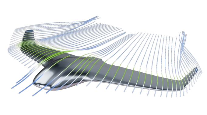
A blended-wing-body (BWB) UAV, such as those used for agricultural surveying, mapping, or surveillance, serves as a practical example of how CAESES and STAR-CCM+ can be integrated to automate the entire workflow – from parametric geometry modeling to CFD-based performance evaluation and design optimization.
The challenge: Optimize lift-to-drag ratio while maintaining trim
The objective was to improve the aerodynamic efficiency of the BWB UAV while satisfying a defined pitching-moment constraint. Unlike conventional aircraft, a blended-wing-body has no tailplane to balance the nose-down tendency of the wide-chord centerbody, making trim an important consideration during optimization.
The specific design task was defined as follows:
- Configuration: Blended-wing-body with a 1.2m wingspan
- Operating speed: 14 m/s
- Prescribed lift: Corresponding to a mass of 1.8 kg
- Optimization objective: Maximize the lift-to-drag ratio (L/D)
- Constraint: Maintain the absolute pitching-moment coefficient at or below 0.005
- Design space: Eight design parameters
Therefore, the goal was not just to improve aerodynamic performance, but to find regions in the design space that would achieve a high L/D while remaining within the specified trim constraint.
Build a parametric model in CAESES
The CAESES workflow begins with the generation of a parametric model. Instead of manually modifying the geometry for every iteration, key design characteristics are defined as parameters.
For the UAV, these include geometric features such as wing sweep, twist, camber, and reflex. Changing a parameter value updates the corresponding geometry, allowing the rapid and robust generation of different configurations from the same model.
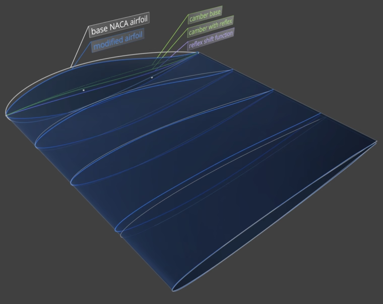
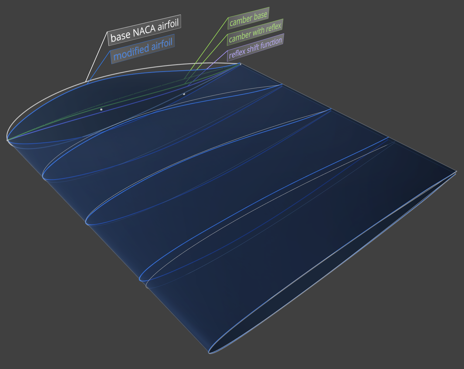
Airfoil sections interpolated by normalized wing surface
The UAV geometry is defined by first establishing its cross-sections. These are derived from specified NACA airfoil profiles at discrete spanwise positions, with each profile modified to incorporate camber and reflex. To ensure a smooth transition between the individual airfoils, they are interpolated using a normalized wing surface (with both chord and span set to 1), allowing the exact cross-sectional shape to be obtained at any desired spanwise position.
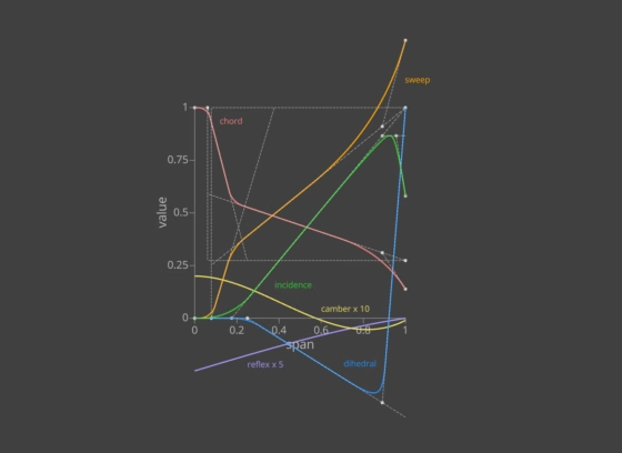
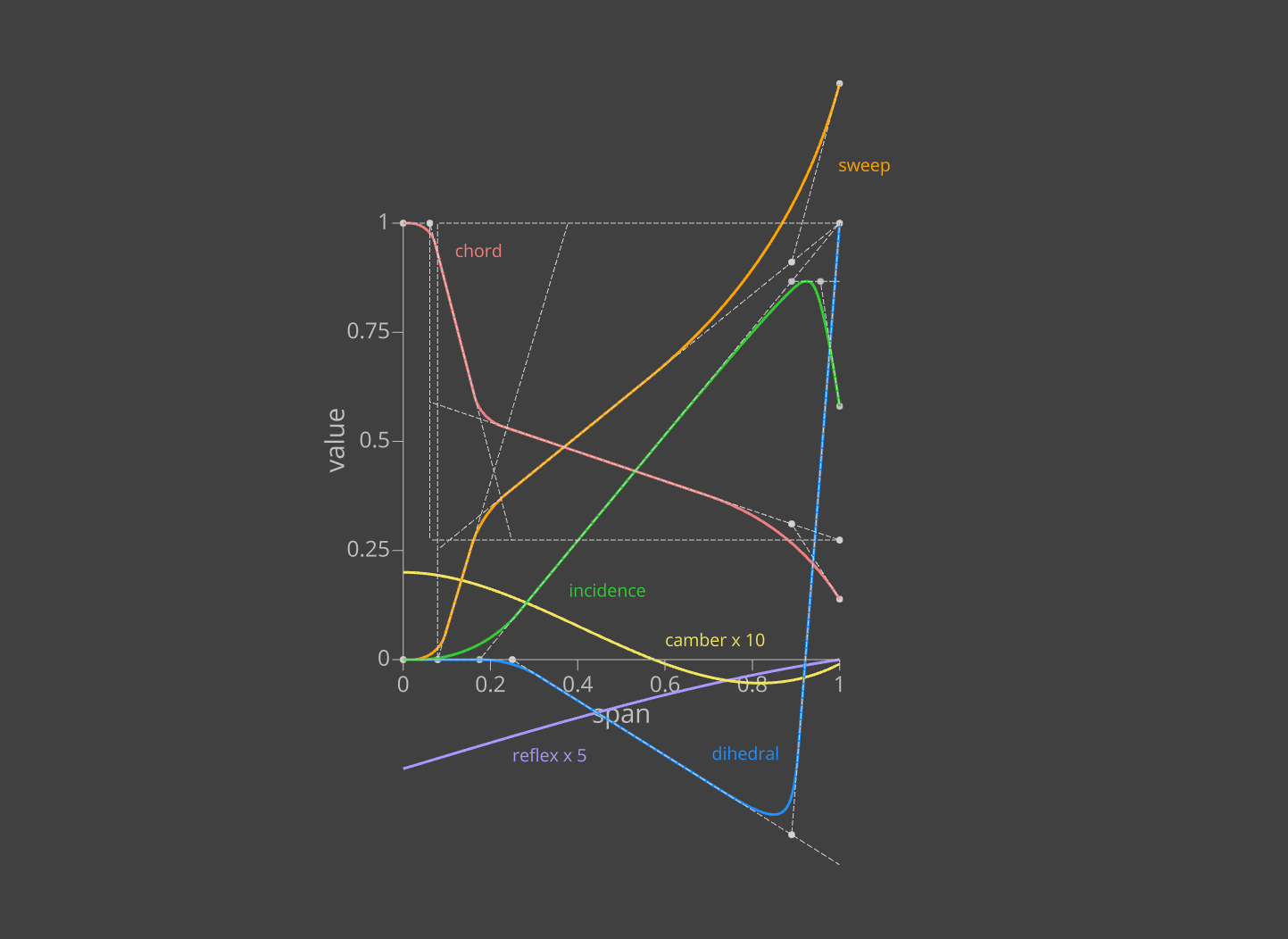
Spanwise functions for the section parameters
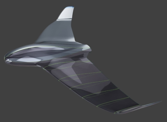
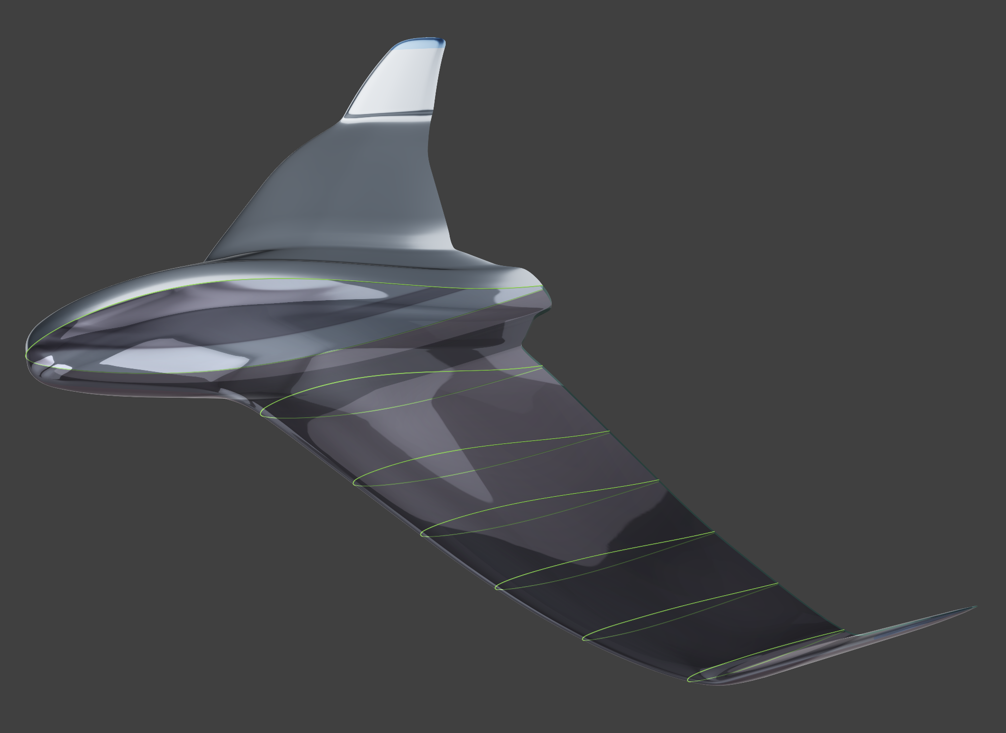
Final geometry with some sections for illustrative purposes
The cross-sectional definition, together with a set of spanwise functions, determines the final wing shape and, consequently, the overall UAV geometry. The design parameters primarily control the shape of these functions, with any parameter changes propagating through to the resulting surface geometry. See the images below for some exemplary variations.
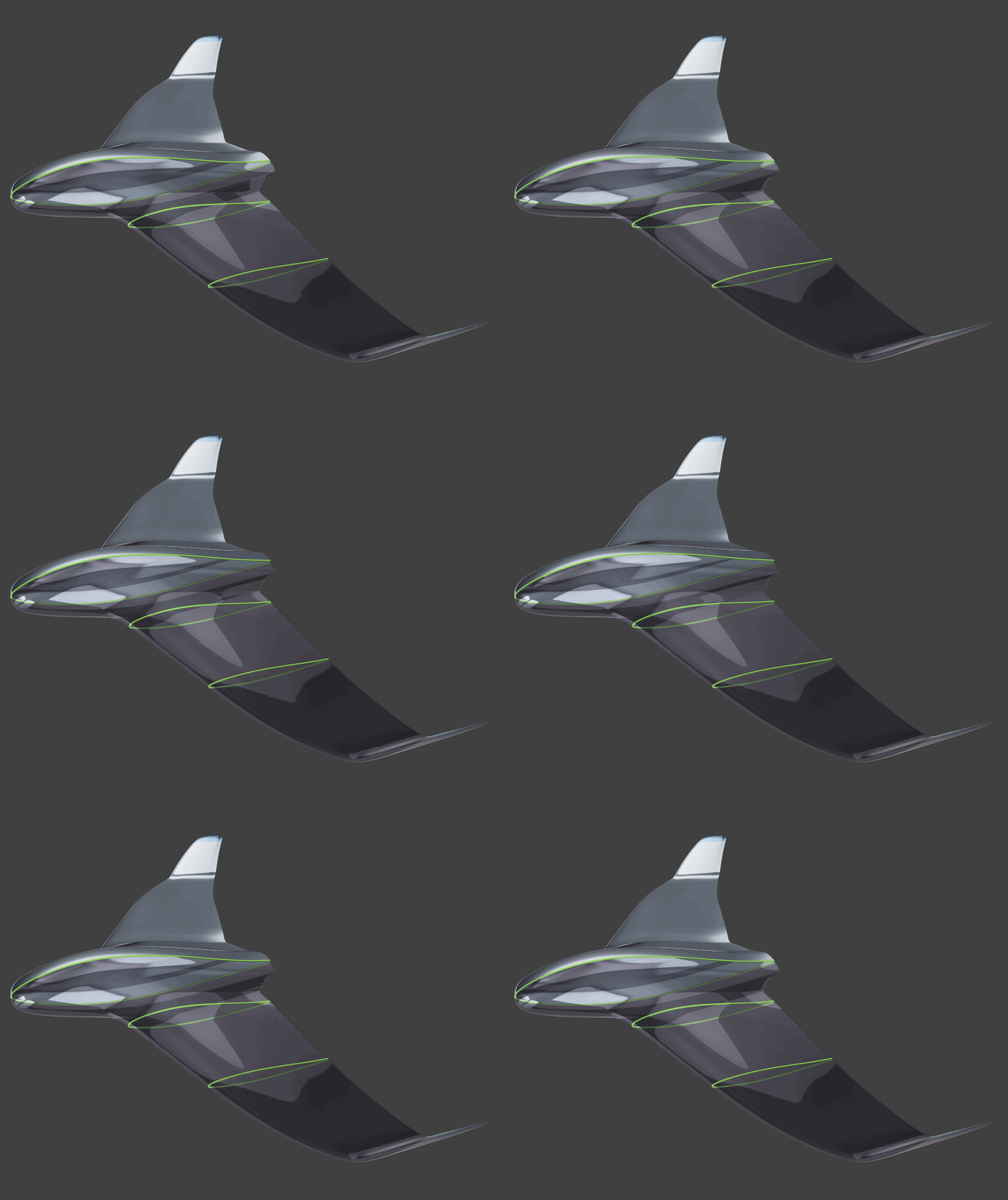
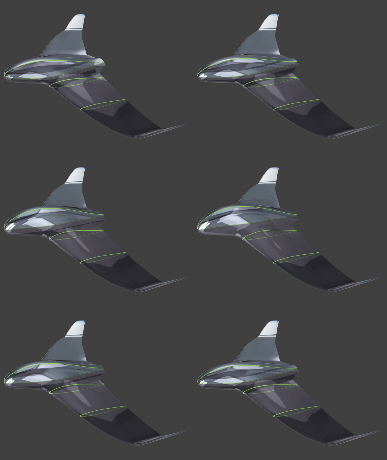
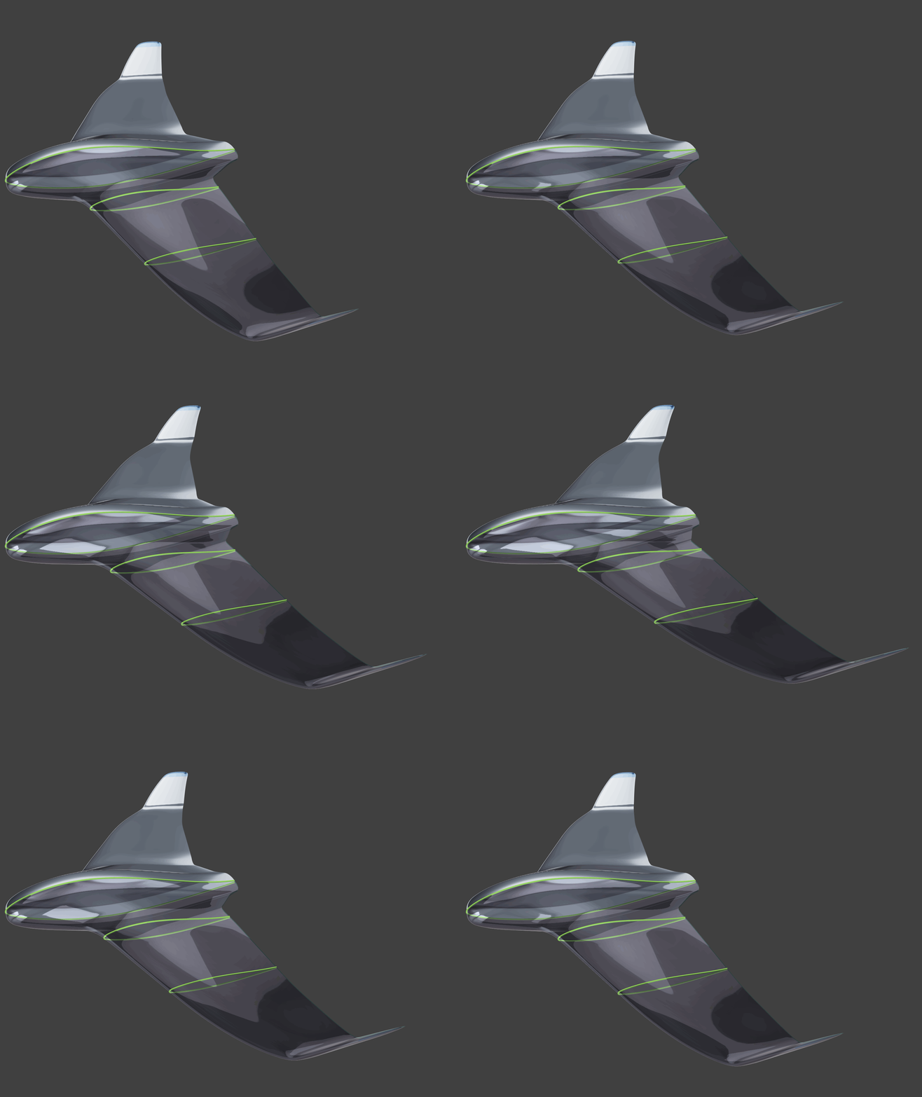
A key requirement for automation is that the generated variants remain valid and suitable for CFD analysis. This reduces the need for manual geometry preparation and helps maintain consistency throughout the optimization process.
Connect CAESES with STAR-CCM+
Once the parametric model is established, it is linked to STAR-CCM+ through the CAESES Software Connector.
The Software Connector automates the data exchange between geometry generation and CFD analysis. For each design variant, the workflow exports the geometry in a suitable format, prepares the simulation inputs, runs the STAR-CCM+ analysis, and returns the required results.
A crucial factor for automating the simulation workflow is the consistent identification of geometric entities, for example, to assign boundary conditions and meshing settings. For use with STAR-CCM+, CAESES exports the geometry in STEP format, assigning distinct named colors to different geometric regions. These identifiers remain consistent across geometry modifications and design variants, allowing STAR-CCM+ to reliably recognize the corresponding regions whenever the geometry is updated or replaced.
The automated loop consists of five main steps:
- Model: Generate a design using the selected parameter values.
- Export: Transfer the geometry and associated information to the CFD workflow.
- Simulate: Execute the STAR-CCM+ simulation using the configured template and previously recorded automation scripts (sim file template and Java macros).
- Evaluate: Return aerodynamic results, including lift, drag, and pitching moment, to CAESES.
- Select the next design: Use the optimization process to determine which parameter combination should be evaluated next.
The process runs iteratively without requiring an engineer to manually launch each simulation or transfer its results between applications.
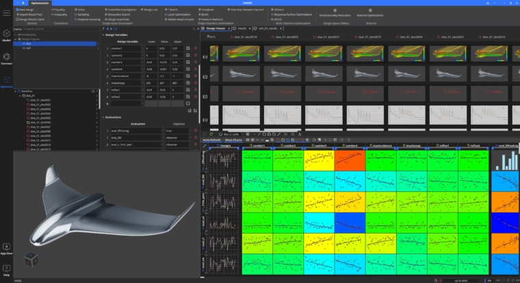
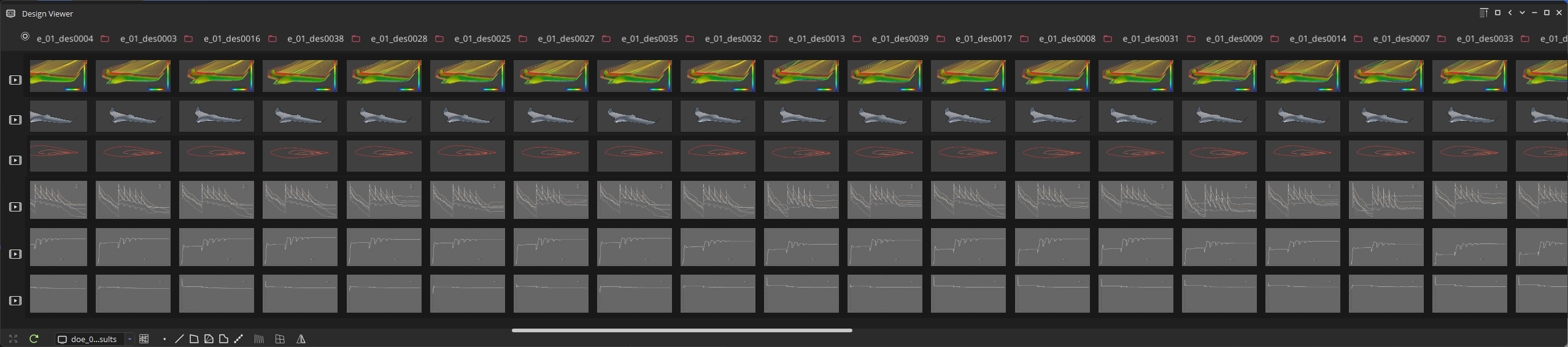
The aerodynamic quantities needed to evaluate the optimization objective and constraints are automatically extracted from tabular data files generated by STAR-CCM+. Flow-field visualizations can be created directly in CAESES by importing EnSight Gold files, or generated externally and imported as screenshots. The same approach can be used for convergence plots, providing a quick visual assessment of simulation quality and solution convergence.
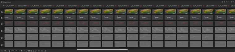
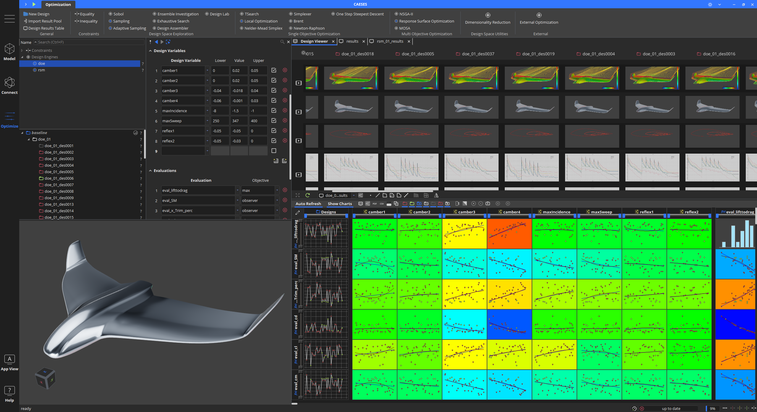
Matrix of geometry variations with CFD results and convergence plots
Automation is particularly useful when a large number of design variants need to be evaluated under consistent simulation conditions.
Optimize the design under constraints
With the geometry and simulation workflow connected, CAESES can coordinate the optimization process.
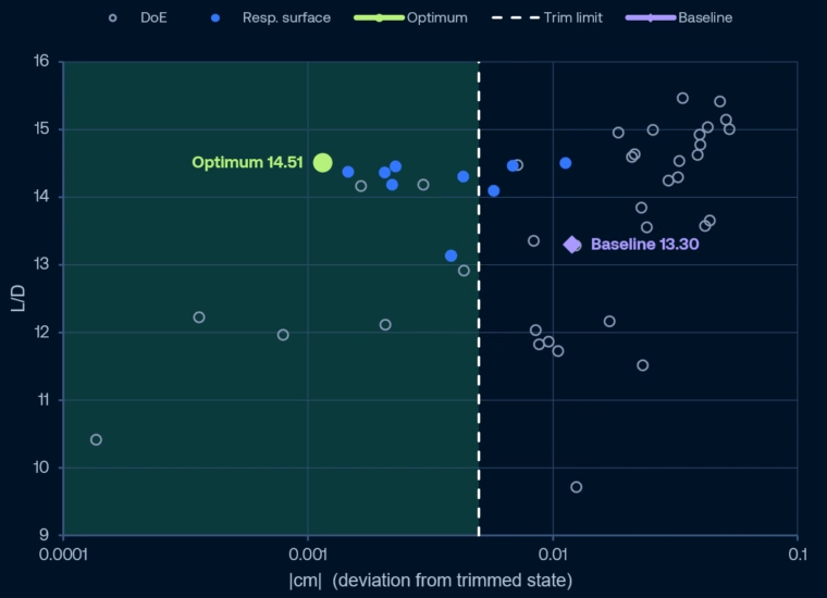
The optimization process began with a Design of Experiments (DoE) comprising 37 design variants generated using Latin Hypercube Sampling (LHS). While the best-performing designs from this initial phase did not satisfy the trim constraint, the DoE successfully identified a promising region of the design space containing variants with improved L/D compared to the baseline design, which itself also failed to meet the trim constraint. Building on these findings, a surrogate-assisted optimization phase was performed using a Multi-Objective Genetic Algorithm (MOGA) operating on the response surface. Ten additional design evaluations were conducted, with the resulting data used for iterative re-training of the surrogate model. This approach allowed the optimizer to further exploit the promising region identified by the DoE and ultimately identify a Pareto-optimal design.
Compare the baseline and optimized designs
The comparison at the same lift condition showed a pronounced improvement in aerodynamic efficiency, alongside a reduction in the pitching-moment coefficient.
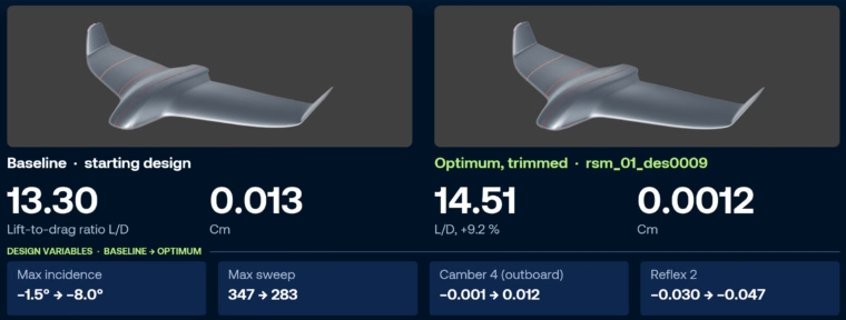
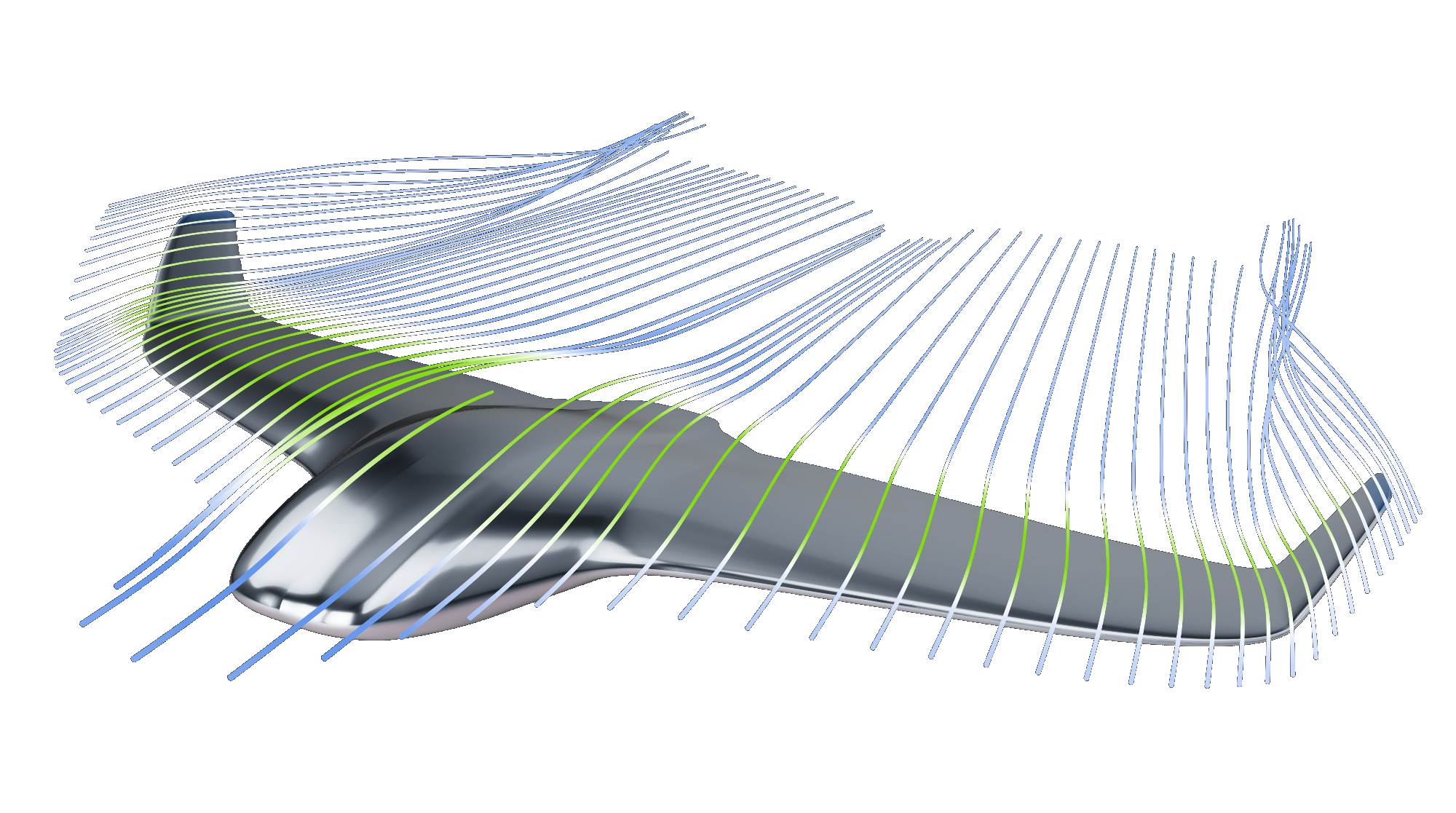
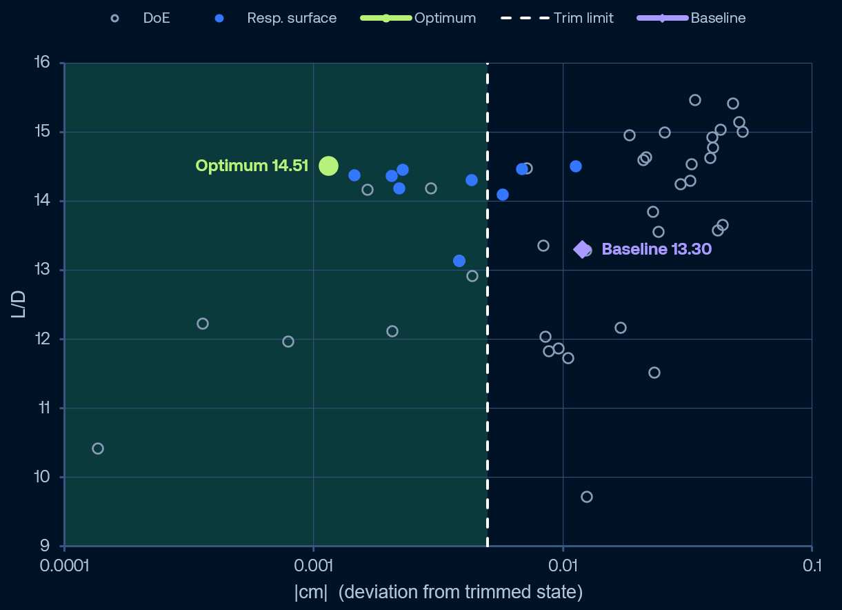
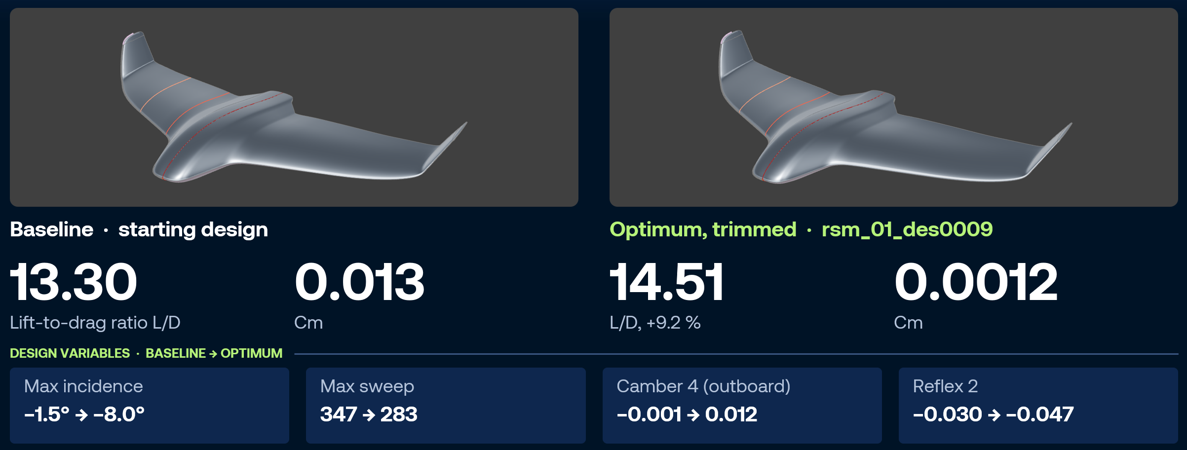
The optimized design increased L/D from 13.30 to 14.51, an improvement of approximately 9.1%.
At the same time, the absolute pitching-moment coefficient decreased from 0.013 to 0.0012. The optimized result was therefore below the specified limit of 0.005.
The results highlight the importance of constrained optimization: improving the objective function alone is not sufficient; the optimization must also ensure that the resulting design satisfies the required pitching-moment criterion.
Apply the same workflow to other engineering problems
The approach is not limited to UAVs. CAESES can also be used to generate parametric geometries and automate simulation-driven optimization workflows for other applications.
Examples include turbomachinery design, ship hulls, engine and other performance-critical components. In these cases, the geometry parameters, simulation setup, performance objectives, and constraints will differ, but the underlying workflow remains similar.
A parametric model defines the design space, the software connector automates the simulation process, and optimization strategies – conventional or based on machine learning – help identify promising configurations based on the resulting performance data.
Conclusion
The blended wing body UAV example illustrates how CAESES and STAR-CCM+ can be combined to automate a constrained aerodynamic optimization workflow.
By linking parametric geometry generation with CFD simulation and optimization, engineers can evaluate multiple design variants without repeating the same manual steps for each iteration. The results provide a measurable comparison between the baseline and optimized configurations: approximately 9.1% higher L/D, together with a pitching-moment coefficient that satisfies the specified constraint.
The broader benefit is consistent, repeatable workflow that connect geometry, simulation, and design decisions. It provides a foundation for exploring more design variants and applying data-driven engineering methods to complex optimization problems.