Compressor blade design
See how Rolls-Royce and CAESES accelerated compressor blade optimization from weeks to days, achieving smoother geometries, lower losses, and improved aerodynamic performance through advanced parametric 3D modeling.

About Rolls-Royce
Rolls-Royce is a global leader in the design, manufacture, and support of aero engines for civil and military aircraft. With a strong heritage in aviation, the company powers some of the world’s most advanced commercial airliners and military jets. Its Trent engine family is widely used in long-haul aircraft, known for efficiency and reliability.
Rolls-Royce is also at the forefront of innovation, developing next-generation engines and sustainable aviation technologies, including hybrid-electric propulsion and ultra-efficient gas turbines, to support the future of cleaner flight.
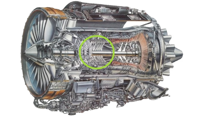
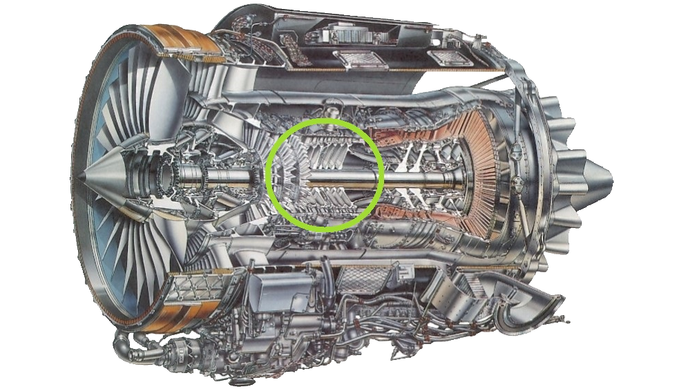
Section view of aero engine with highlighted compressor section
Courtesy of Rolls-Royce
The challenge
In the pursuit of reducing emissions and fuel consumption, aeroengine manufacturers face the intricate task of refining aerodynamic compressor designs. This process is notably time-intensive, involving numerous iterations between geometry generation and numerical flow analysis to achieve optimal blade geometries that align with global performance requirements. Specifically, the challenge lies in realizing the necessary flow turning and blade loading with minimal losses, while also extending the off-design operating range.
To address this task, Rolls-Royce Deutschland (RRD) had developed a method for optimizing axial compressor blades using multi-objective optimization focused on working range and design point loss for a selected number of individual sections. Each blade section was modeled with B-Spline curves and defined by 25 parameters, subject to constraints to ensure feasible designs. Due to the large design space and the extensive evaluations required, optimizing a single section took around 5 days. The final 3D blade geometry was then constructed by stacking the optimal trade-off solutions – those with the highest working range – from each section's Pareto curve along the radial direction.
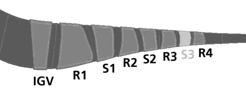
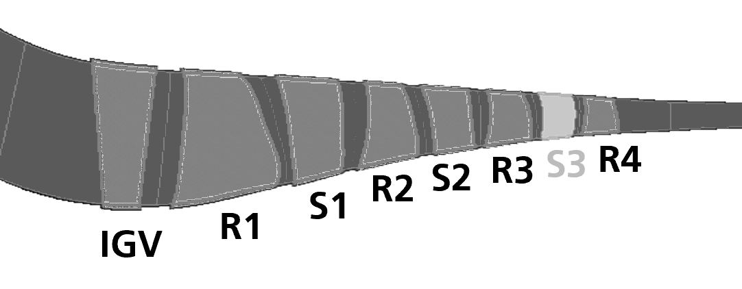
Location of S3 compressor blade subject to optimization
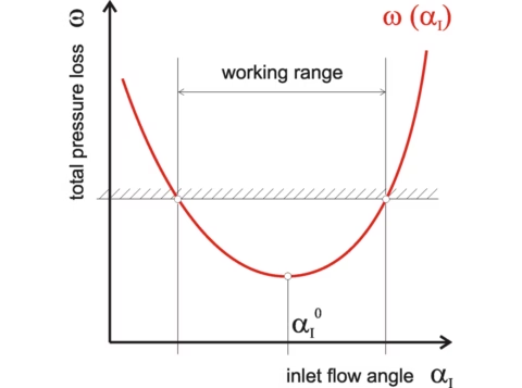
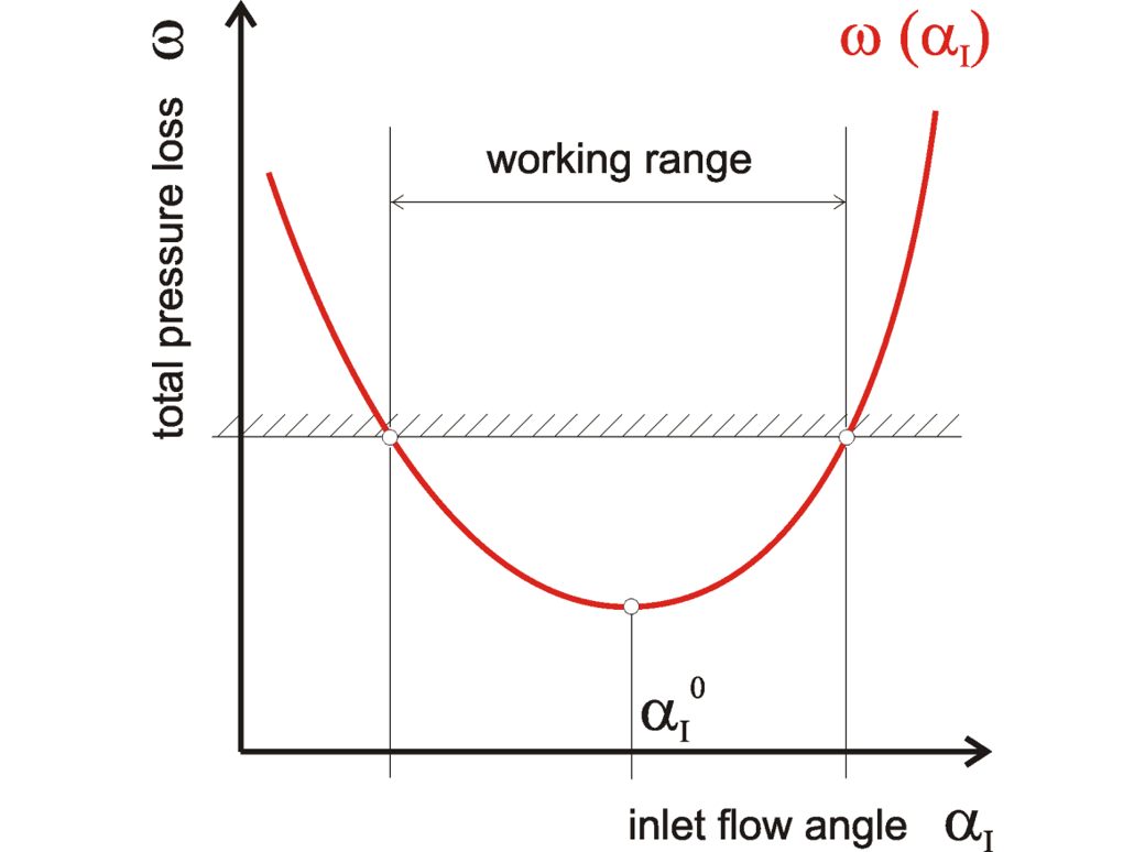
Blade section loss curve for variable inlet flow angle
The solution
In a project with RRD, FRIENDSHIP SYSTEMS developed a new method for the direct generation and variation of the 3D blade geometry in CAESES – aimed at reducing the number of defining parameters while ensuring a smooth, high-quality blade shape. This approach introduces smart flexibility, particularly in the hub and tip regions, where geometric changes can be more complex, balancing accuracy, efficiency, and control.
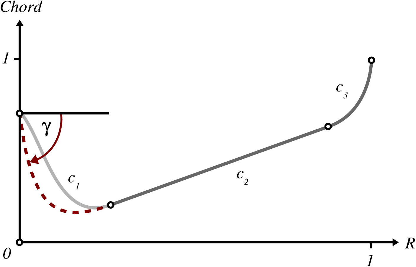
Resulting from a thorough analysis of the radial distributions for existing blades, the method is based on a uniform parameterization using three combined radial curves to define each blade parameter consistently along the radius. Two fairness-optimized parametric curves provide design flexibility at the hub and tip, while an optional linear curve connects them smoothly through the mid-span, reflecting the often-linear behavior in that region. Designers can use up to 12 parameters per radial quantity. For example, adjusting the tangent angle of the first curve – as illustrated on the right – allows targeted changes in the hub region without altering other parts of the blade.
In addition, the optimization is treated as a single-objective problem targeted at reducing the combined design point losses across multiple sections. As the parameters are defined for the radial distributions, only the number of CFD evaluations scales with the number of sections and not the size of the design space.
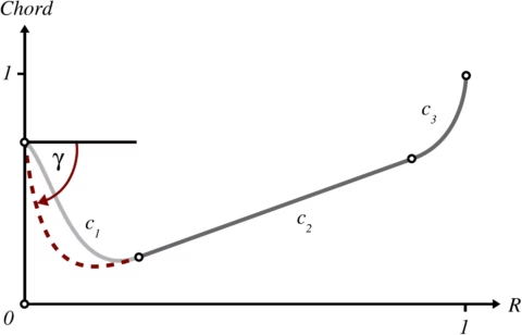
Exemplary radial distribution function for chord length
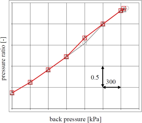
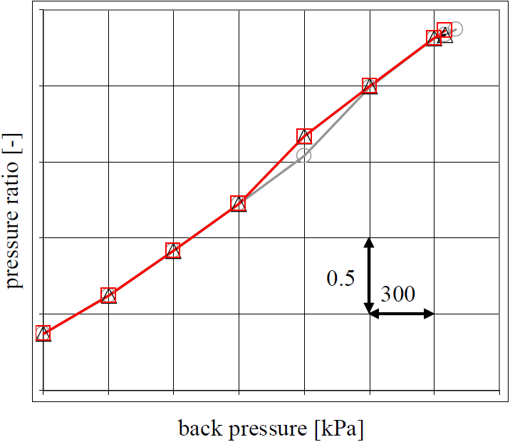
Pressure ratio plot over operating range
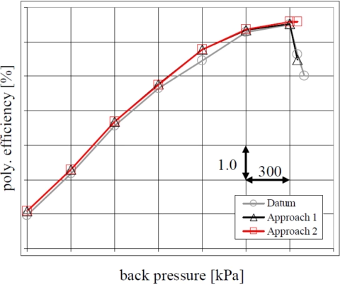
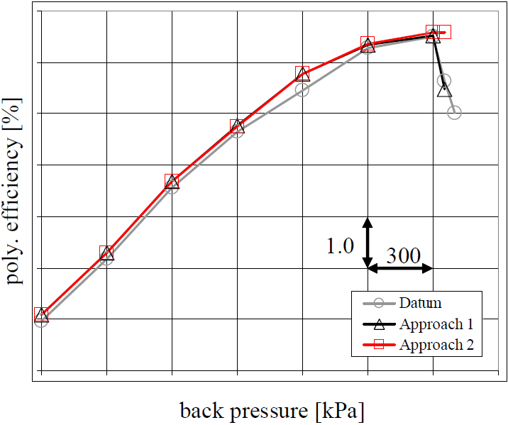
Efficiency plot over operating range
The benefits
A comparative study revealed that both approaches yielded similar aerodynamic results:
- A 0.25% reduction in stage losses.
- Expanded the working range by 1.5° in flow angle.
However, the approach centered around the parametric 3D blade model demonstrated significant advantages:
- Accelerated design time: Reduced the design cycle from several weeks to between 1 and 5 days.
- Smoother shape: More advantageous in terms of stress issues and manufacturing.
- Enhanced insight and confidence: Provided deeper understanding and greater confidence in the design outcomes.
This case study underscores the efficacy of CAESES' parametric 3D geometry approach in accelerating design processes and achieving performance enhancements in aeroengine compressor blades.
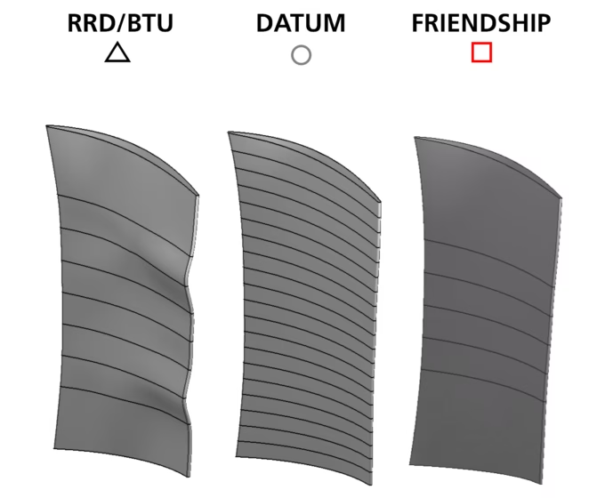
Optimized blade geometries for the two approaches
More case studies
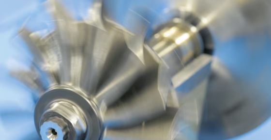
Turbocharger impeller design
Using CAESES, mtu Solutions implemented a fully automated, multi-objective optimization workflow for turbocharger design, integrating aerodynamics, structural, thermal, and mass analyses to deliver near-production solutions with over 50% reduced development time and engineering efficiency gains.
Compressor blade design
See how Rolls-Royce and CAESES accelerated compressor blade optimization from weeks to days, achieving smoother geometries, lower losses, and improved aerodynamic performance through advanced parametric 3D modeling.