


Mr. Carsten Fuetterer
-
Content Count
168 -
Joined
-
Last visited
-
Days Won
3
Posts posted by Mr. Carsten Fuetterer
-
-
Hi Johann
the tutorial was written for OpenFOAM 2.x. Since then a lot of syntax from OpenFoam have changed. In your case it is pretty clear that the syntax of the definition of the turbulence model has changed. Just look into a openFoam tutorial eg the motor bike one, to see the correct syntax.
best regards
Carsten
-
Hi Suraj,
as long you can work with CAESES, you can ignore these errors.
best regards
Carsten
-
Hi there,
thanks Paulo for helping out with this interesting papers.
The term impeller is just a general description for turbomachinery blades. Turbine blades are also some kind of impeller.
With the method described in the video, you can create turbine-, compressor- & fan blades. The stream section, which is used to create the camber surface, allows you to set the flow angles (beta angles) or the wrap angles (theta angle).
best regards
Carsten
-
Hi Suraj,
can you work with CAESES or does it crash, when you open the 3D View? Can you post the output of -> getGLInfo() from the console?
best regards
Carsten
-
Hi Bikash,
I would probably use an approach using streamsections. See this video for some reference:
best regards
Carsten
-
Hi Bram,
you are right to use the matrix4 command. See the attached example for this.
best regards
Carsten
-
Hello Tariq,
I think it is still not clear to us. Here is what I understand:
- you have a baseline geometry and perform a Moga study and you come up with a pareto front
- now you pick a design from this run (not on the pareto front) and perfom another MOGA with the same variable setup and come up with another pareto front
- now you are wondering why the designs of the two pareto fronts look different?
best regards
Carsten
-
 1
1
-
Hi Bodo,
an image curve will be default be the exact curve as the source curve. When you change the parametrization to e.g. "Unit Speed", then the curve will be approximated with new control points to fit the original curve within a certain approximation tolerance.
The command .setNumberOfEvaluationForParametrization() is not used anymore and should not have any effect on the curve.
The default value of the approximation tolerance is 1e-5

best regards
Carsten
-
1
-
-
Hi Xavier,
sounds strange. CAn you upload your current project?
best regards
Carsten
-
Hi Xavier,
what do you mean with "connection file". Do you mean the batchscript to run the open foam tools?
best regards
Carsten
-
Hi Stefan,
in case of a propeller blade I don't know why to use trimmed surfaces. A subsurface from a brep will not work. So the only case, where I can think of problems is the blade analysis, but here trimmed surface can be avoided pretty easy I guess.
best regards
Carsten
-
Ah ok, no we can not create a "new" Nurbs surface from a trimmed one.
regards
Carsten
-
Hi Stefan,
now I don't get your point. You can use any brep to convert to stl, no matte if it is trimmed or not. I am not seeing your problem.
Carsten
-
Hi Stefan,
you can change the tesselation in the display option directly on the Brep Part. When you put this Brep into a triMesh the tesselation is used directly from the brep.
best regards
Carsten
-
Hi,
the surface sensitivity gives you a scalar field, which describes the amount you have to push or pull the surface cell inwards or outwards to lower the objective function.
The design velocities in CAESES gives you the information how one design variable changes the shape normal to the surface.
In CAESES you then combine the surface sensitivity with the design velocities, and you will get the parametric sensitivities of each design variable, which describes the gradient of objective function change to design variable change. This means you know then how much you have to change one design variable to change the objective function. You also know the influence of each design variable on the objective function.
best regards
Carsten
-
Dear Kim Moo Sung,
before you calculate the parametric sensitivities in CAESES, you need the surface sensitivities from a adjoint calculation, which comes from the CFD code. Does Simerics has an adjoint solver?
best regards
Carsten
-
Hi,
please have a look into this post:
https://www.caeses.com/forum/index.php?/topic/415-connect-caeses-with-excel/
best regards
Carsten
-
Hi Hamidreza,
you are right, Maxsurf doesn't provide a batch mode.
What you could do is to prepare an master project from where you trigger the project with the com integration. In that way you could use the software connector in the master project and the standard design engines. You would need to control CAESES with an fsc file.
With that you could trigger as many CAESES instances as you have CAESES licenses.
best regards
Carsten
-
Hi Hamidreza,
you cannot use the COM via SSH. You could run CAESES on the other machine though.
Which program do you use, and is there a way to access to the program without COM interface in batch mode?
best regards
Carsten
-
Hello Hamidreza,
at the moment it is not possible to trigger multiple COM applications at the same time. In general this would be possible to implement it into CAESES, but at the moment this is not at high priority.
In most cases COM connections are pretty fast, so that there is not a big need to run it in parallel. But we can think about it, to implement it in future releases.
best regards
Carsten
-
Hi Suraj,
for this kind of propeller you can simply cut the tip with a cylinder. This is done with a brep operation "solid from intersection". Therefore you have to extrude the blade a little bit in both directions, which is done in the brep "blade".
best regards
Carsten
-
Hi Suraj,
I created a new post for this:
https://www.caeses.com/forum/index.php?/topic/676-file-io-how-to-read-a-file-with-a-feature/
best regards
Carsten
-
Hi,
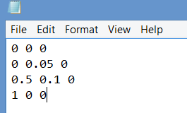
if you want to read data from text or csv files it's fairly simple to do it in a feature definition.
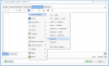
We use a simple file like this:

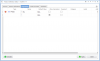
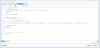
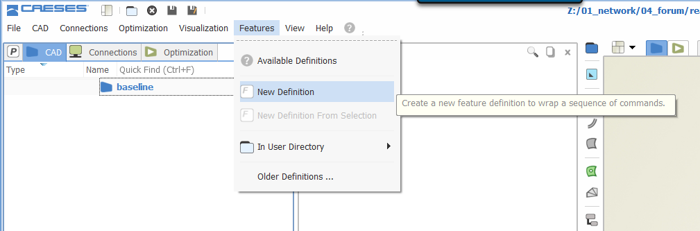
To start we create a new feature definition:

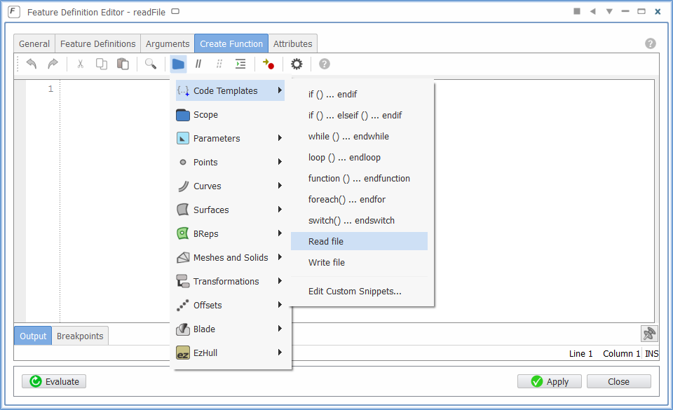
In the "create function" tab, we can use the code templates to create a basic control structure:
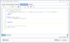
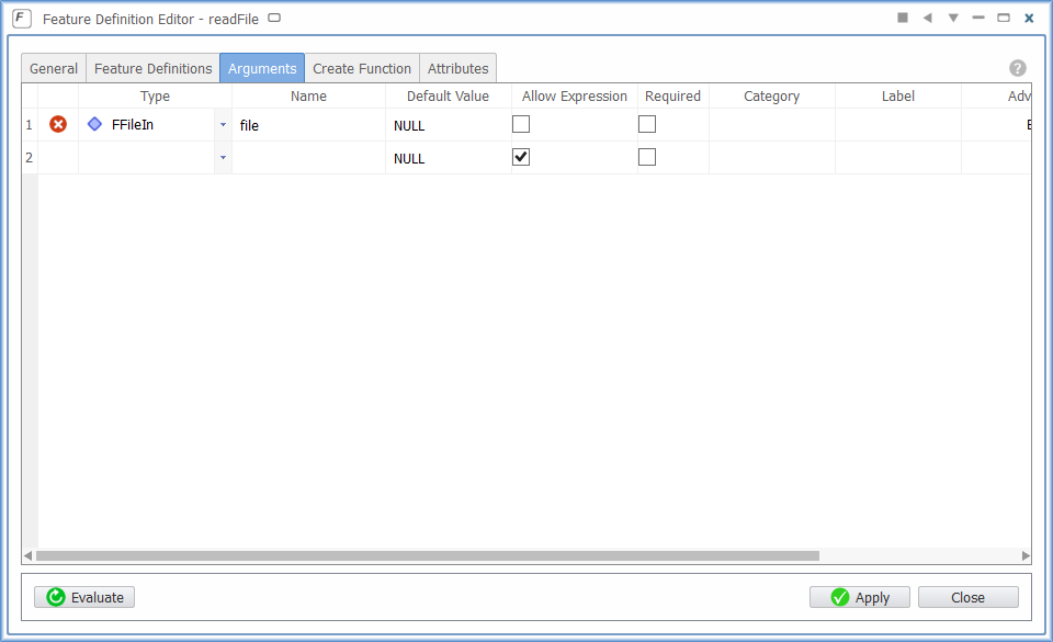
The variable "FilePath" is not defined and has to be supplied with an argument. In this case I want the object "file" as an argument. So I comment the first line from the feature and create an new argument:
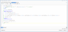
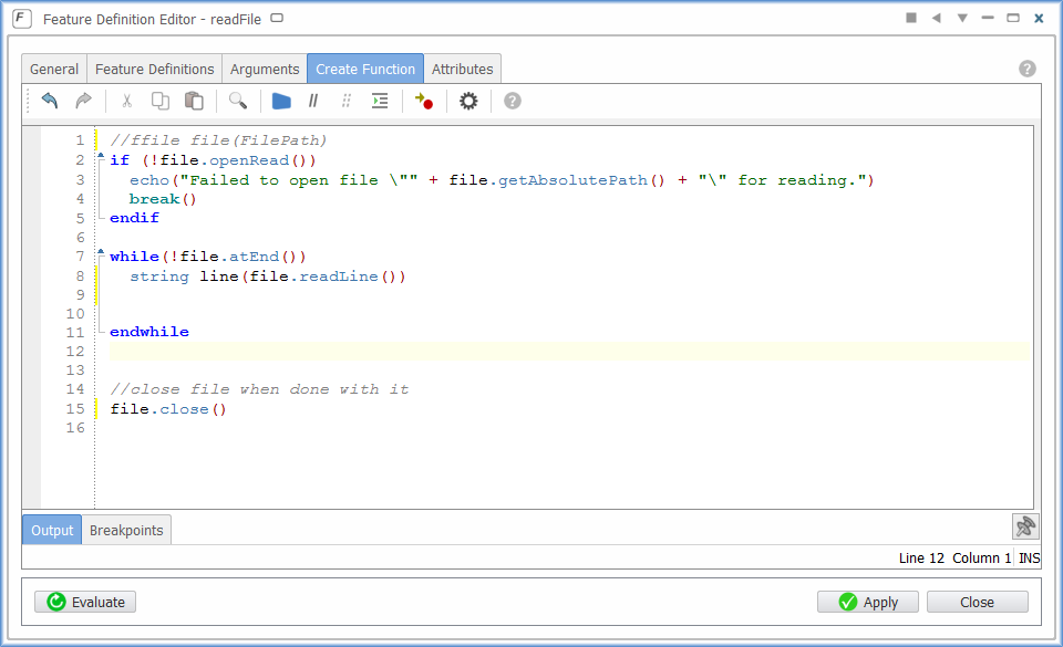
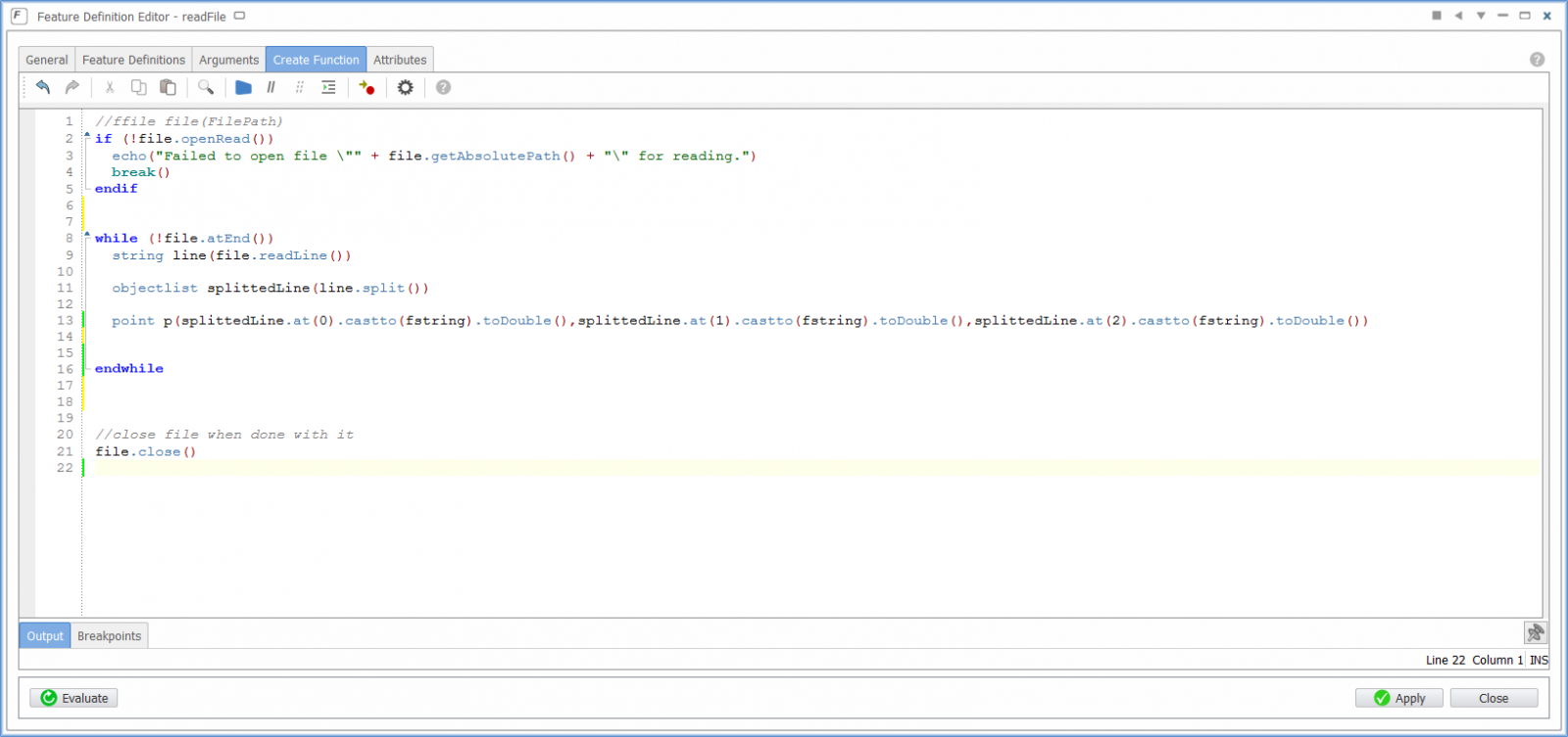
The feature code looks like this:
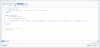
You can see that a string is create for each line of the file. So now we have to split this string in order to access the double values. Therefor I use the split command, which has the output of an objectlist. Then I create a point, which accesses each value of that object list:
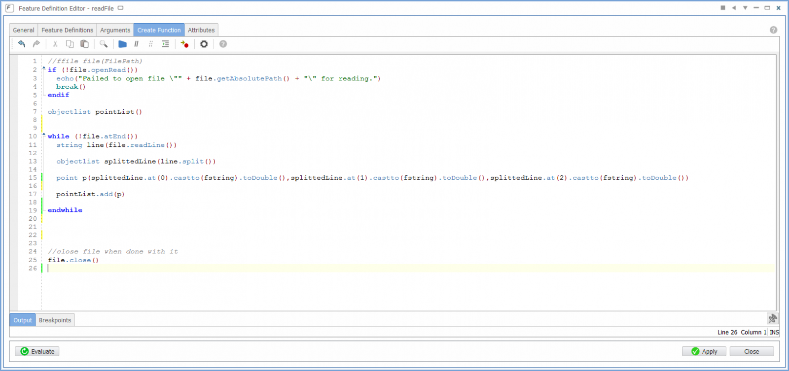
Now we have to store the points for each line inside an extra objectlist.Therefor we create a new list and add the point:
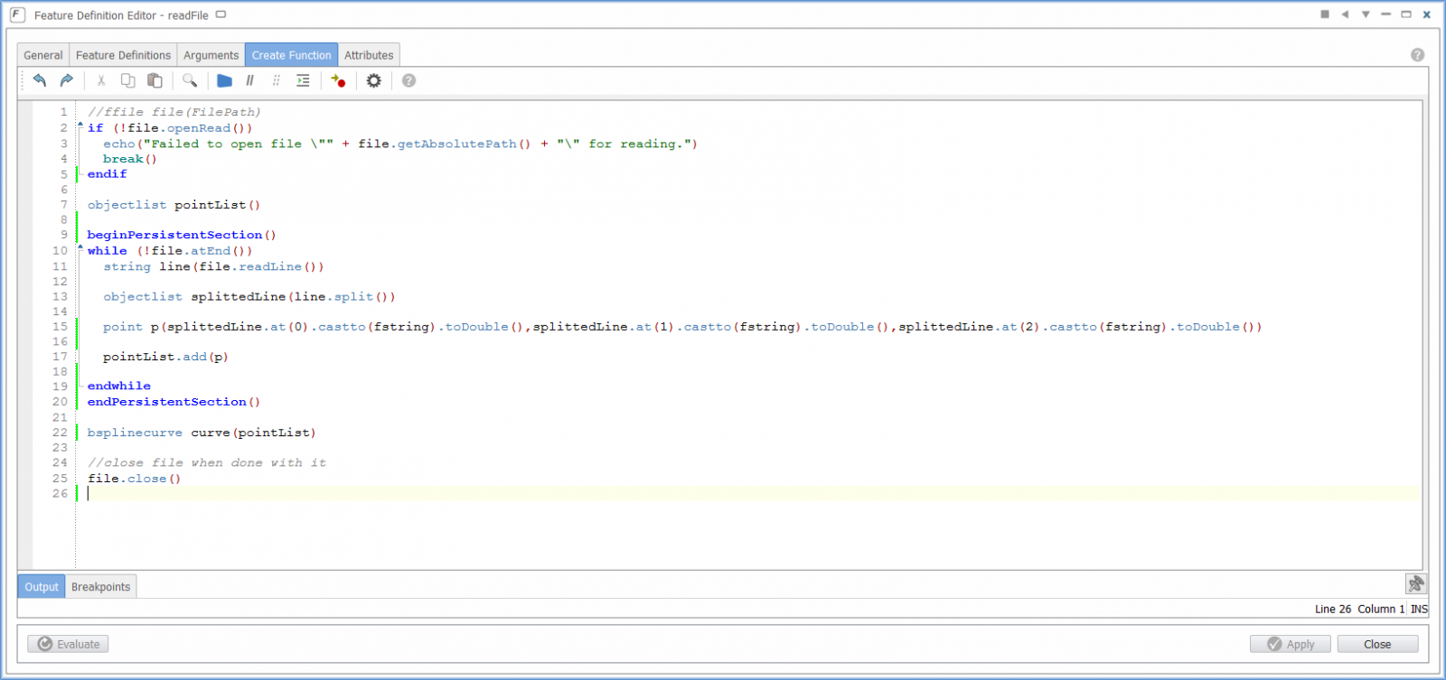
Finally we create fore example an bsplinecurve, with the new list of points. Additionally encapsulated the while loop into a persistent section in order to visualize the points for each loop. Otherwise we would just see the last point.
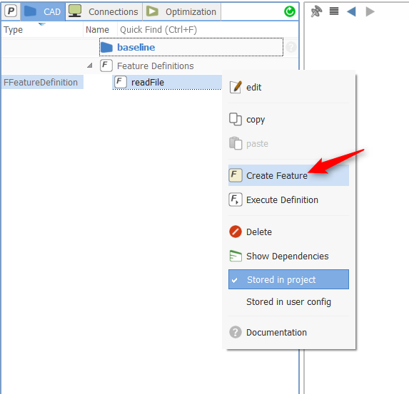
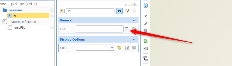
Now we create the feature from the feature definition:

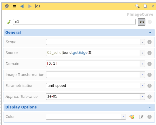
We set the path to the reference file:

This nice dialog only appeared, because we didn't allow expressions for the argument inside the feature definition:

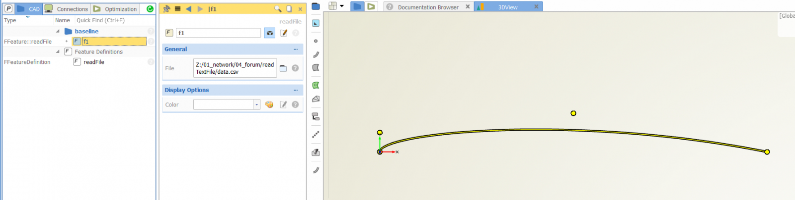
The final curve:

I hope this helps you to create you own custom file reader.
best regards
Carsten
-
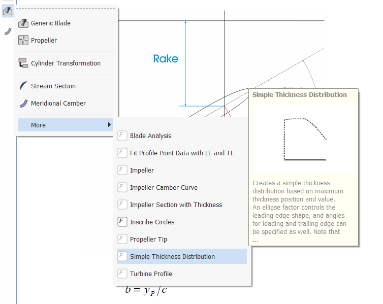
Hi Suraj,
you could directly implement a part of an circle or ellipse inside the thickness distribution. You can have a look into this feature to see how it is done:

best regards
Carsten

SSH Resource Manager Deployment
in Installation
Posted · Report reply
Hi Moritz,
this problem is probably due to a version clash of your mariaDB database and the corresponding JDBC driver. You probably have mariaDB 10.1. Try to install the lastest mariaDB version (10.3) which is provided on the download page of mariaDB.
By the way your current student license will not allow you to use the resource manager. I will send you an email.
best regards
Carsten