


Mr. Heinrich von Zadow
-
Content Count
223 -
Joined
-
Last visited
-
Days Won
12
Posts posted by Mr. Heinrich von Zadow
-
-
Dear Anand,
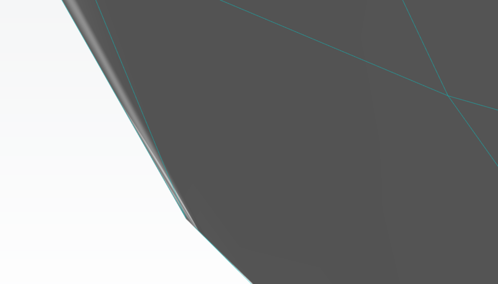
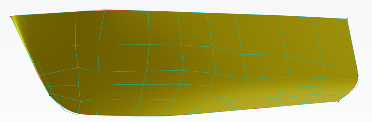
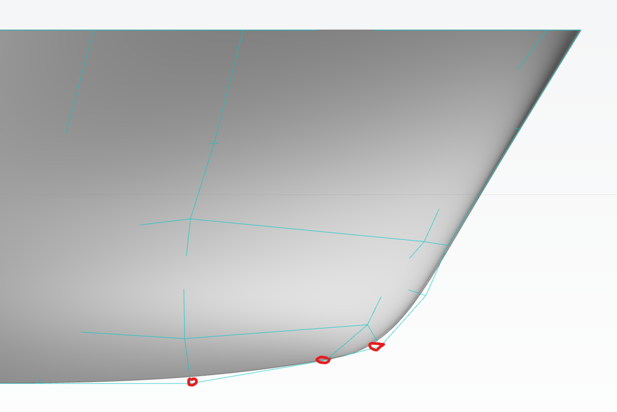
I took a look at the hull surface you started with. The control polygon looks a bit distorted. I suggest, you sort that out first -- especially the bow region seems to have some folding issues, as you can tell from the attached screenshots.

After adjusting the control polygon in this region a little and sorting out a few other things (which probably won't occur if you start with a better surface right away) I managed to get everything to work as intended, although you might want to spend some more time on the fairing!
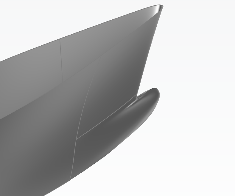
Most importantly you should focus on getting the control points shown in the following picture into a straight line (the middle one is the corner of the surface and there is one point currently very close to it, which needs to be exactly the same!)

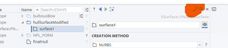
To adjust the control points, you can use the edit mode:
I also moved the project to our latest release of CAESES5 which is why the file type is now a *.cdbc.
Cheers,
Heinrich -
Hi Atiyah,
I would recommend that you take a look at the Lackenby (there is also a tutorial "Lackenby Hull Variation"). It is a partially parametric modelling technique that allows you to set both, longitudinal center of buoyancy and prismatic coefficient (and thereby displacement) at the same time.
Best regards,
Heinrich -
Hi Christina,
what you need is a design variable that gives you control over the volume, without changing the length. i.e. the beam of the bulbous bow should work fine. You then need to set up a nested optimization (for example a Brent) that adjusts the beam to match the target volume. You should find plenty of material about these so called "nested optimizations" if you search the forum.
Cheers,
Heinrich -
This might not be the perfect forum for this kind of question since CAESES is not a CFD tool, but rather a parametric CAD and optimization platform that allows you to connect any CFD (or other external) software. However, as far as I know, there is -- and has been for a long time -- extensive research carried out in the field of alternative surfaces both on micro and macro scale. Whether you would actually model these things (e.g. fish-like scales or certain roughness and patterns) or just treat them specifically in your CFD code via boundary conditions depends. Both ways are feasible and have their pro's and con's.
Cheers,
Heinrich -
Dear RWM,
please provide some more information so that I can understand what you are having trouble with.
Best regards,
Heinrich -
Hi Christina,
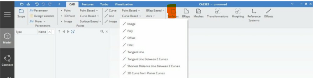
you are looking at curves, not surfaces (both have a category "curve based"). On your screen it seems that surfaces are collapsed:
If you are on a small screen this is probably fine. Otherwise, you can change the font size by pressing ctrl and scrolling the mouse wheel.
Best regards,
Heinrich -
Hi Christina,
if you are working with the latest (currently 5.0.6) version of CAESES, you should find lofted surfaces in the category of curve-based surfaces:
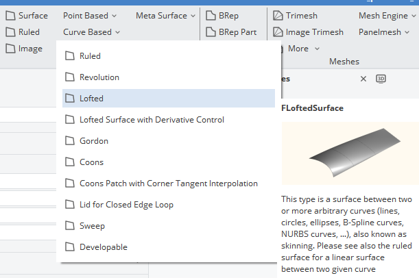
I am not aware that this is excluded from non-commercial packages. apart from lofting you might want to take a look at sweep surfaces or, if non of the "standards" works for your application dig into the topic of meta surfaces.
Cheers,
Heinrich -
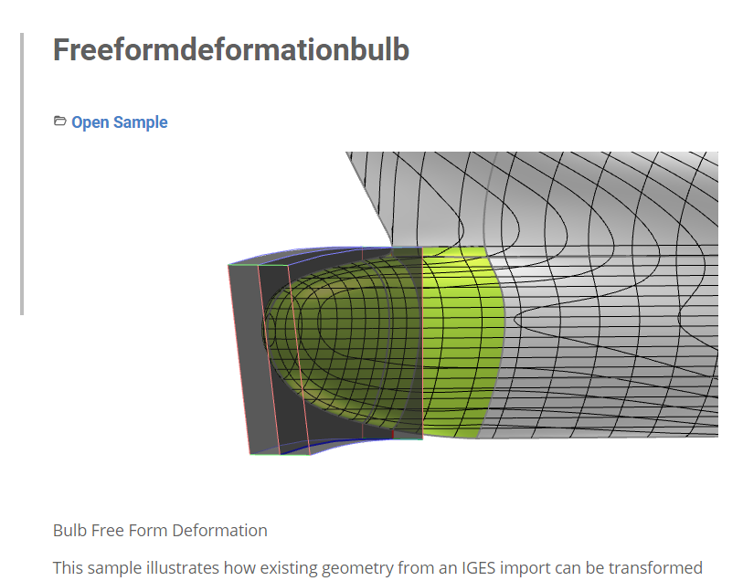
Dear Christina,
as mentioned in the other post, you can refer to the "freeformdeformationbulb" tutorial to get a very basic idea of how to apply a ffd to modify an existing bulbous bow. This is one (out of a much larger set) of the available morphing techniques that come with CAESES5. For a bulbous bow I can also definitely recommend to look into delta shifts and BRepMorphing. With these 3 you should have absolutely everything you need to modify an existing bulb geometry. For an optimization of a bulbous bow I would definitely recommend to include some variation of the forward shoulder (so you can achieve a favorable cancellation of waves) as well. Once you do that, you will probably also need to keep an eye on hydrostatics (check if the Lackenby suits your needs) to avoid shifting the LCB to much, or changing the displacement beyond what's feasible for your application.
We have recently hosted a Webinar about morphing capabilities in CAESES5 which might be interesting for you ("How to Efficiently Optimize your Geometry with Morphing in CAESES 5") here: https://www.caeses.com/support/videos/
About the optimization, there are plenty of other tutorials and useful guidelines included in the documentation that should give you a good starting point.
Hope this helps to get you started.
Best regards,
Heinrich -
Dear Christina,
the file Rull has posted further up seems to be very similar (if not identical) to the sample we ship with CAESES5. Just search for it in the help workspace (bottom left corner of the GUI) and you should find this:
Best regards,
Heinrich -
Dear Atiyah,
I recommend to start with the general documentation and then work your way forward through tutorials and samples. There is plenty of maritime-specific material on fully, as well as partially parametric hull-design available to get you started.
Best regards,
Heinrich -
Dear Mr. Saeed,
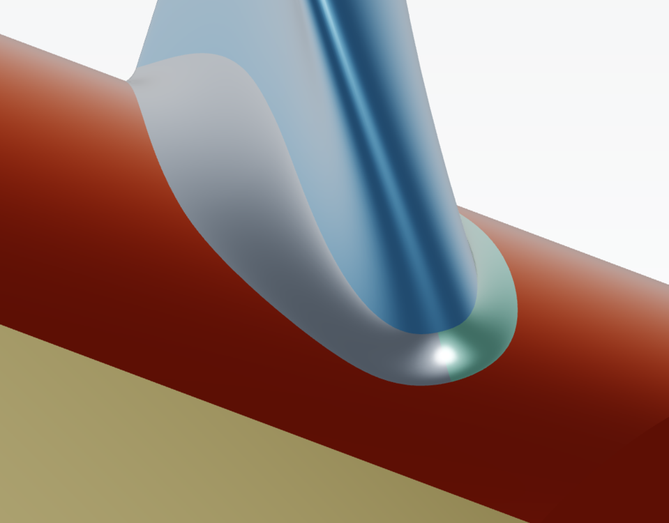
although I have no experience with such a design I am positive that something like this could be modelled with CAESES. Instead of the standard blade modeling functionality I would go for a meta surface to create the special shape. You could model the central u-turn-curve (dashed line in your last picture) first and then create the blade along this path while providing functions like chord, pitch, thickness etc. along this path.
I guess, if you check the propeller and meta-surface tutorials and samples you should have a good idea how to proceed. Fell free to get back to me in case you get stuck.
Cheers,
Heinrich -
Dear Chien,
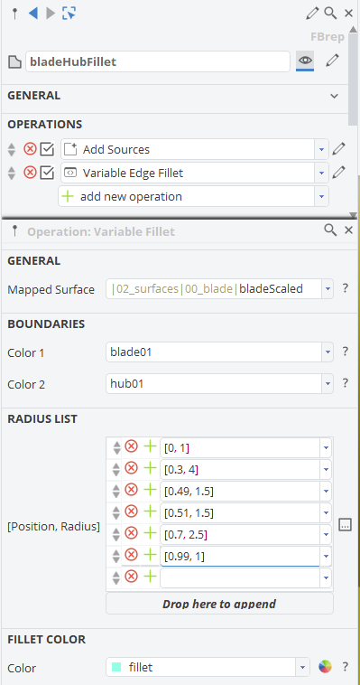
the position value is parametric. I modified the input surfaces for your blade such that now (0=start, 1=end and anything in between depends on the internal parametrization of your input surfaces, i.e. knot vector, control points, degree, etc...). Practically, in most cases you would need to know your leading edge position (now 0.5) and you can simply find out which side is suction and pressure by trial and error.
I recommend that you move the hub seam out of the way (by adding 180° to the start and end of the hub contour).
Also the trailing edge doesn't look ideal.
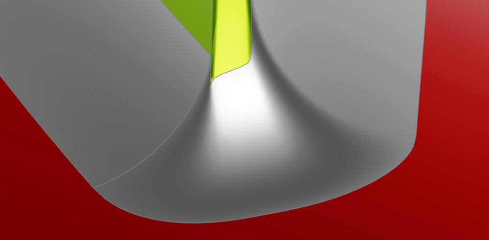
I increased the tangent factors of the underlying fillet surface as a simple fix:

Not sure if it makes a difference in this case, but please note, that I used the new 5.0.4 release.
Unfortunately I couldn't get the variable fillet to work right away, either. I will try to find some time to take a closer look.
Cheers,
Heinrich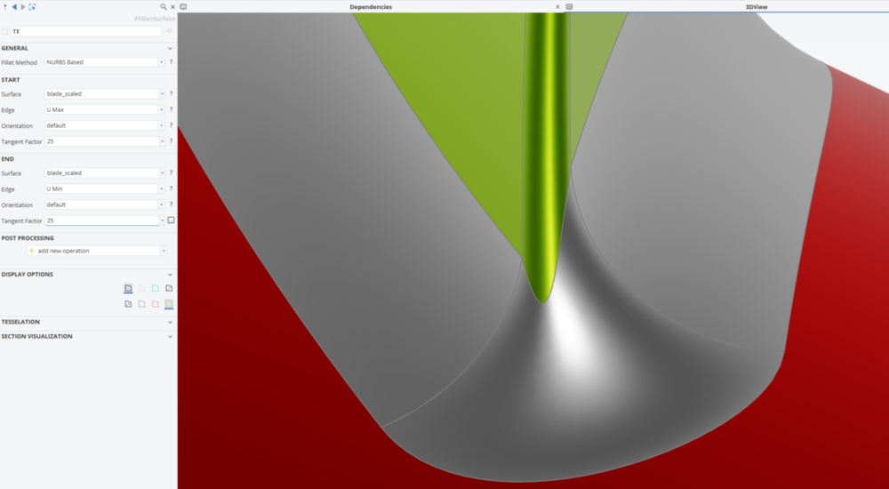
-
Here we go, thanks Paulo!
-
Dear Chien,
why don't you upload yours? Probably even more helpful for you...
Cheers,
Heinrich -
Dear Chien,
yes, this is possible, although a bit tricky at times because you will need a very clean model to begin with...
The result would look something like this:
The corresponding settings here where as follows:

Cheers,
Heinrich -
Hi Carsten,
didn't know that, I guess this is new with CAESES 5 -- thanks for filling me in.
Cheers,
Heinrich -
Hi Rohan,
not directly. Best option would be two trimeshes "trimesh01" and "trimesh02" (one for each surface) and an imageCurve "c1" with the source "trimesh01.getShortestDistanceLine(trimesh02)". You can then create a parameter with "c1.getLength()" for the actual distance.
Cheers,
Heinrich -
Hi Rull,
I looked at your project and it works just fine -- see attached animation. I guess there will be some tweaking of the spacing and transformations of the points to get some really good shapes, but technically, it works. Did you make sure you look at the image surfaces and not the initial ones?
Cheers,
Heinrich
-
Hi Rull,
I can not tell this from the picture alone. Did you set the FFD as a transformation (create and image surface from your existing bulb or assign it to a BRep if that's what you have). If you can't get it to work, feel free to attach your project here.
Best regards,
Heinrich -
Dear Rohit,
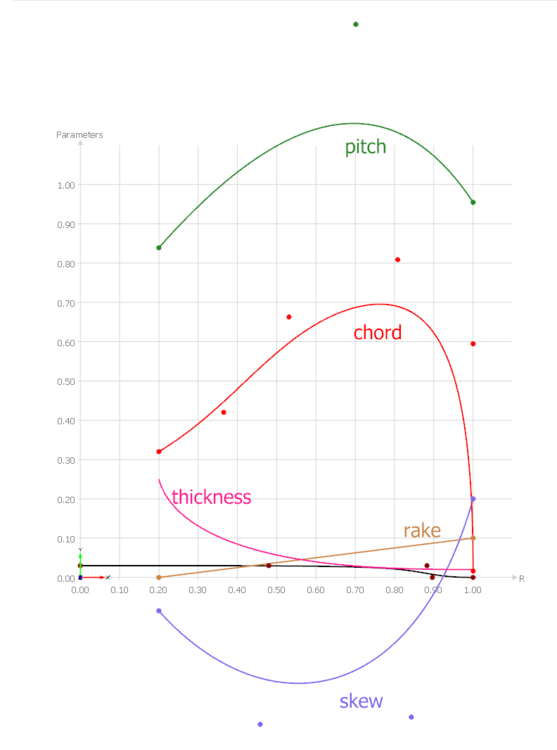
the design variables are used to describe/modify the functions given in 01_blade/functions. You can see how they affect their shape in 3D:
You can find detailed information on their exact definitions in the documentations. To get there, just click the little blade icon next to the name of the blade:
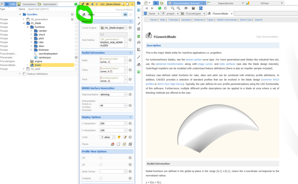
Best regards,
Heinrich-
 1
1
-
-
Hi there,
you might want to start by extracting the underlying surfaces of your BRep (create a BRepPart from it and then right-click > extract underlying surfaces) and take a look at them. If they are suitable (somewhat rectangular and nicely parameterized) you can get away with creating panel meshes from them directly. In my experience there will probably be at least a few regions which you have to re-model in order to get suitable patches for mesh generation.
Cheers,
Heinrich -
Hi Zhen,
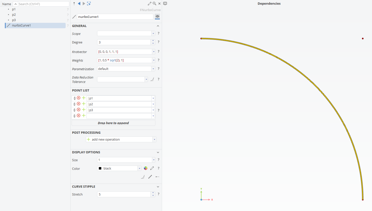
just a small addition in case someone else stumbles across your question. For an actual (perfect) circle you can not use an F-Spline. Behind the scenes an F-Spline is a B-Spline curve, optimized with respect to fairness and constrained at start, end, start-tanget, end-tangent, curvature, enclosed area, etc... That means, if you set the area as the area of a circle and also match the tangent at start and end you will get something that is really close to a circle, but not a perfect circle.
For an actual (quarter of a) circle, you need a NURBS curve with 3 control points. The weight of the center point needs to be set to 0.5*sqrt(2).

In order to keep the area constant while moving points 1 and 3 (in your picture), I suggest a delta shift and a brent (you can search the forum for nested optimization to see how the brent algorithm can be used to adjust the area to a certain target value).
Cheers,
Heinrich
-
Hi Gunnar,
very good. If you would like me to take a look at the mesh, feel free to upload it.
Best regards,
Heinrich -
Hi Gunnar,
You imported an STL file. Try using s STEP or IGES if you can. (These are not discretized, but NURBS-based) If you can get your hands on such a format, you can technically get to the underlying surfaces. However, they might be untrimmed and hence, not work for generation of your panelmesh. To check, create a BRepPart and use right-click "extract surfaces".
If STL is all you can get, you don't want to put that in a BRep, but rather use Trimeshes and Solids. For trimeshes (maybe you can get one with higher resolution) you could try the right-click "split by angle". This should make quick work of the reparametrization of the individual faces.
Best regards,
Heinrich


Optimize Hull Form with Constant Displacement and Cb
in Variation & Optimization
Posted · Report reply
Hi Atiyah,
the working mechanism ist the same for both (actually, the Lackenby is also a Delta Shift). A function is defined along the ship which defines by how much the geometry is shifted at the respective longitudinal position. As you can imagine, this easily allows to shift the longitudinal center of buoyancy and adjust the displacement. Since this is such a common task in hull design, we offer the Lackenby which allows you to manipulate prismatic coefficient (CP) and longitudinal center of buoyancy (LCB) simultaneously.
So basically, there is no difference except that you can use the Lackenby if this is what you need, or alternatively set up the geometry variation all by yourself through a standard Delta Shift... E.g. you could also use a delta shift to move the design waterline up and down without changing the height of the hull...
A typical scenario of the Lackenby being used in an optimization would be to fix LCB and CP all the while the geometry is modified. This way, you can better compare the different geometry variants on a "fair" level (Otherwise you would often just find that the geometry variant with lowest displacement has lowest resistance, which is usually not what you where looking for...). Also, often times these two measures are fixed constraints, anyways...
Like said, there is a Tutorial that covers the complete setup.
Cheers,
Heinrich