


Mr. Heinrich von Zadow
-
Content Count
223 -
Joined
-
Last visited
-
Days Won
12
Posts posted by Mr. Heinrich von Zadow
-
-
Dear Milad,
If I understand correctly, then yes, that is perfectly normal. The 2000 LHS samples is what you use to train the model. If you'd evaluate your model at these exact points, the prediction would perfectly match the training data (at least for Kriging that is the case). However, the model cannot just predict a pareto front "out of the blue". Usually, what we do is, to run a MOGA (multi objective genetic algorithm) optimization on the model. With large enough populations sizes and number of generations this allows to quickly find pareto-optimal designs (that means that for those designs there is not other designs better in one objective without being worse in an other objective).
Best regards,
Heinrich -
Dear Yuwen,
the code is not that straight forward to explain. Mostly it's sine/cosine distribution functions, but there are quite a few additions here and there. Would you not rather need a topology like outlined in the attached project, anyway?

Cheers,
Heinrich -
Dear Yuwen,
I'd have to ask a developer to take a look into the code to answer that question. However, I think it might be enough for you to know that the distribution (if not set to be uniform) is dependent on the parametrization of the underlying surface. Hence, by parametrizing the surface differently, you can freely control the distribution of cells.
Cheers,
Heinrich -
What exactly did you do when "running Dakota". Did you run an optimization or just calculated one set of pareto designs? Could it be that the blue dots in the second plot are additional samples that where generated before the generation of the first Surrogate?
-
Hi Milad,
I am not quite sure if I understand the question. You mean that out of the 2000 LHS samples only a few are shown after you have calculated the pareto designs? Do you create the plots in Excel and add the pareto designs from the finaldata file?
Cheers,
Heinrich -
Hi Carlos,
I think I remember these black BReps from the good old CAESES4 days 😉 If I recall correctly this happens when importing IGES/STEP from certain other CAD tools and can be easily resolved by just assigning a different color to the imported parts. Since they are currently black, you would have to use the BRep operation "remove colors" first and then assign a different color...
Best regards,
Heinrich -
Hi Ravi,
sweet! Happy to see that you arrived at a design you are happy with so quickly. If you don't mind attaching your project here, I could take a look into the hub shape.
Cheers,
Heinrich -
Hi Andreas,
maybe I am missing the point, but where exactly does CAESES come in here? If you think there is anything our software can help you with, feel free to get in touch!
Anyway, I guess my next try would be a STEP export. Also make sure to use the same units with both tools so you don't run into trouble with tolerances.
Cheers,
Heinrich -
Hi Milad,
very good! Yes, you can export the content of tables to csv like this:
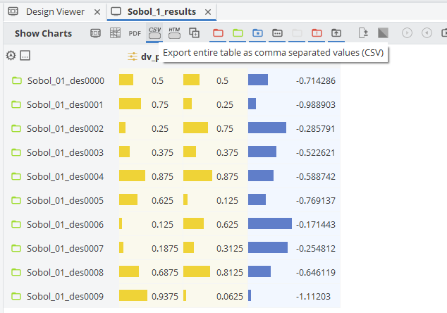
If you want to plat any of the other designs (i.e. the "finaldata" designs returned by dakota) you would have to do the formatting by yourself.
Cheers,
Heinrich -
Hi Yuwen,
at this moment we don't really have this kind of functionality. However, you might want to check again after the next release 😉
In the meantime I attached a quicksort algorithm feature from this old post from Arne:
Cheers,
Heinrich -
Hi Alexis,
the documentation can be searched i.e. for "String" which pops up all the corresponding class functions. You should be able to achieve what you are looking for with the replaceByString command:
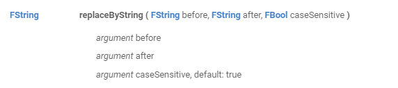
The problem with the backslash symbol is, that it is also used as an escape character. Therefore you need to use a little workaround e.g. as follows:
FString s("a/b")
s.replaceByString("/","\?")
s.replaceByString("?","")
Cheers,
Heinrich -
Hi Yuwen,
it usually means that you try to modify an object that you are not allowed to (in order to prevent recursion). If you just need the max value, you could (inside a feature) use a doubleSeries like this:
FDoubleSeries values([1,2,3,4,5,4,3,2,1])
FDouble maxVal(values.getMax())
Cheers,
Heinrich -
Hi Milad,
there is no option to visualize them currently -- we are definitely planning to introduce that at some point though.
The finaldata file (especially, if you choose a high number of "solutions considered") basically contains the points that lie -- according to the model -- on the pareto frontier. However, the results will definitely be improved a lot if you integrate your calculations into CAESES. The design engine would then automatically verify these candidates and add the new results to the model. This will not just increase the accuracy of the model, but it will do so particularly in the region of interest --> that' why we see such fast convergence with this optimization technique in many cases.
Cheers,
Heinrich -
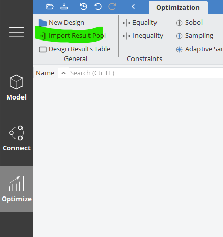
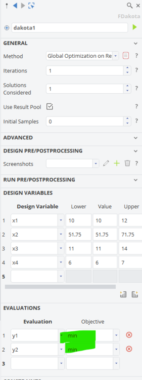
Hi Milad,
yes, that's exactly what I did. Is there any particular reason why you are using 4.4?
If you set up a Dakota Design Engine with the method "Global Optimization on Response" you can choose to use the existing result pool and when you start the Design Engine you can select the table you have just imported. Dakota will then generate a surrogate, run an optimization on it and return the predicted optimum (or multiple pareto-optimal designs in case you have a multi-objective problem and specify "solutions considered" > 1). You can look at the predicted optima in the "finaldata" file in you result directory.
The procedure described above is more like a work-around. Usually the idea is, to couple your simulation tool with CAESES and then have the predicted optima evaluated automatically through CAESES. The surrogate model would then be re-generated with the new variants which increases the accuracy of the prediction. The procedure then repeats...
Cheers,
Heinrich -
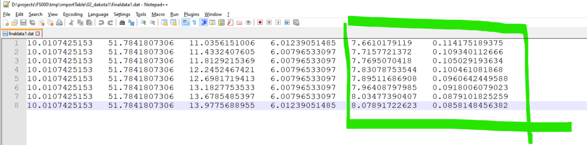
Hi Milad,
that looks to me as if you have generated these results manually (or through a different tool/script)? Usually, when you set up your design in CAESES and run the simulations through one of the optimization engines, you will have a result table which you can use right away. Alternatively, you could always use Dakota/Surfpack though the command line... In your case, with some changes to the formatting (I did a quick search and replace of \t\t with \t to get rid of the double-tabs), you should be able to import the existing results into CAESES and create a Surrogate aka. Response Surface Model from them. I quickly did that to take a look at the data -- see attached project file. To get a good fitting Surrogate I recommend using a more suitable sampling algorithm (usually Latin Hypercube or Sobol is what we recommend, Adaptive Sampling would be the more advanced option). For the model itself, there are different options available (Kriging works well for most cases I came across recently but depending on your problem you might also want to try out Artificial Neural Networks or Radial Basis Functions...).
For now, the parameters y1 and y2 are just dummies, so they do not return the correct evaluation. However, you can still run an optimization on the existing results and then look into the generated "finaldata1" file to check the predicted optimal designs. As I didn't know better, I specified to minimize y1 and y2 and attached the results. You can easily change that in the Dakota Design Engine.
These are the predicted optimal candidates:

Hope this gives you a good point to start.
Cheers,
Heinrich -
Hej Ravi,
I don't think that the Torqeedo props are a standard series. Might be that they use some well known section definitions but I don't think they share these information.
Designing something that looks roughly like the picture (at least the outlines) will be easy, but you cannot expect to get proper performance this way. What I'd recommend at the very least is, to use a suitable series for the sections (Naca66mod could be a good starting point. Might be that you have to thicken it a little more if you are going for a 3D print), find out the pitch of the original (or, even better the pitch that suits your needs) and then use the propeller sample project that comes with CAESES to adjust chord, skew, pitch etc. distributions along the radius.
Cheers,
Heinrich-
 1
1
-
-
Dear Christina,
what is shown in the video is just an example of parametric geometry modelling. In CAESES you typically define parameters to be used within your model. If you change their values, the geometry is changed as well, depending on how you used them. Parameters can not just hold double values, but also complex expressions (mathematical and also wrt. other objects in your project).
In addition, any parameter can be turned into a DesignVariable (just select it and click the check box in the object editor). Design Variables can NOT hold expressions, but just doubles (or integers, if specified) and additional lower and upper bounds. The main point here is that Design Variables are the type you use if you want to automatically change their values through a Design Engine (like an optimization algorithm that changes the DVs to modify the geometry to find the optimum shape...)
Hope this clarifies things a bit for you. You will also find detailed explanations, as well as samples and tutorials in the CAESES documentation.
Cheers,
Heinrich -
Hi Carlos,
in this case you might just want to visit our website and download the latest CAESES5 release:
https://www.caeses.com/downloads/
cheers,
Heinrich -
Hi Carlos,
could you please update to the latest release and check if the problem persists?
Cheers,
Heinrich -
Hi Assiouras,
it's quite simple: fdb is the file format of the CAESES4.x and older releases, while cdb is the current format of CAESES5.x. There is no backwards compatibility (you can open an fdb in CAESES5 and save it as cdb, but not the other way around), hence the different file type. In addition, anything with an additional "c" indicates a non-commercial license and therefore cannot be opened with a commercial license.
Best regards,
Heinrich-
 1
1
-
-
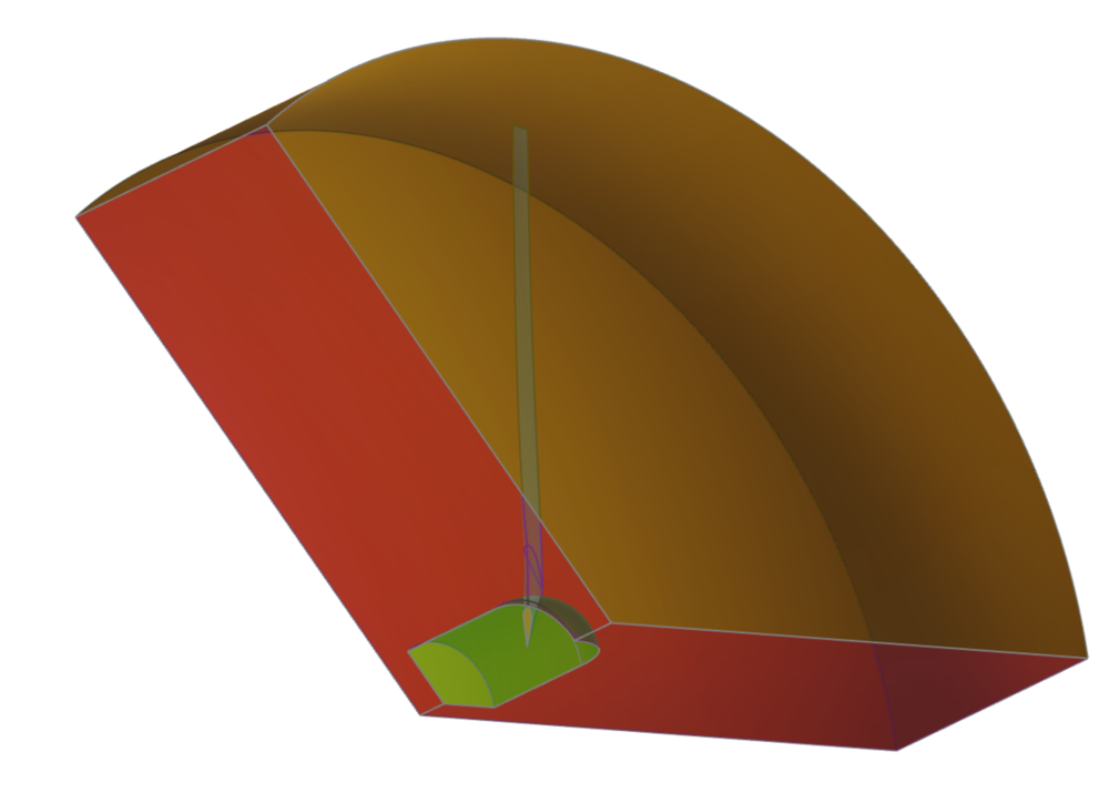
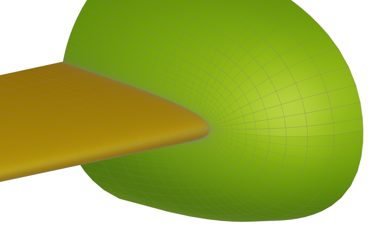
Hi Armagan,
I took a look at the project. From what I could see, the solid blade was not generated correctly. I adjusted a few settings as follows:
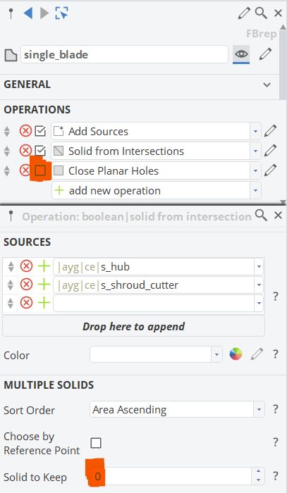
From there it looks as as if everything works well and you get the correct flow domain:
Cheers,
Heinrich -
Dear Armagan,
generally speaking, CAESES 5 offers backwards compatibility -- you should be able to open files from CAESES 4, but not the other way around. However, there have been some changes to Feature Definitions and also to the CAD Kernel which might needs some small adjustments in the projects to make it work in CAESES 5. If you can share the project, I could take a look.
Best regards,
Heinrich -
Dear Atiyah,
you are very welcome. About the file you might want to get in touch with my colleague Daehwan Park -- his mail is shown in the screenshot you sent.
Best regards,
Heinrich -
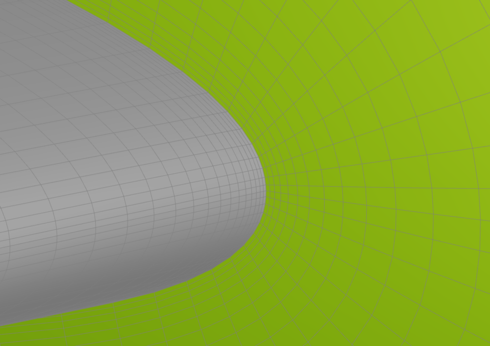
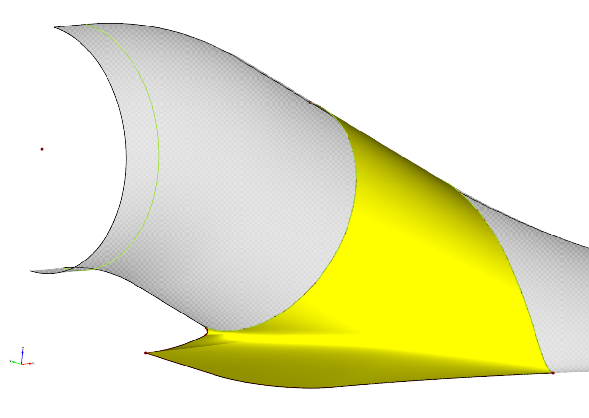
Dear Nuttarat,
I am sorry that I didn't find some time to look into this earlier. From what you have sent, it can be seen, that the discontinuity in the rail of your surface causes the irregularities:

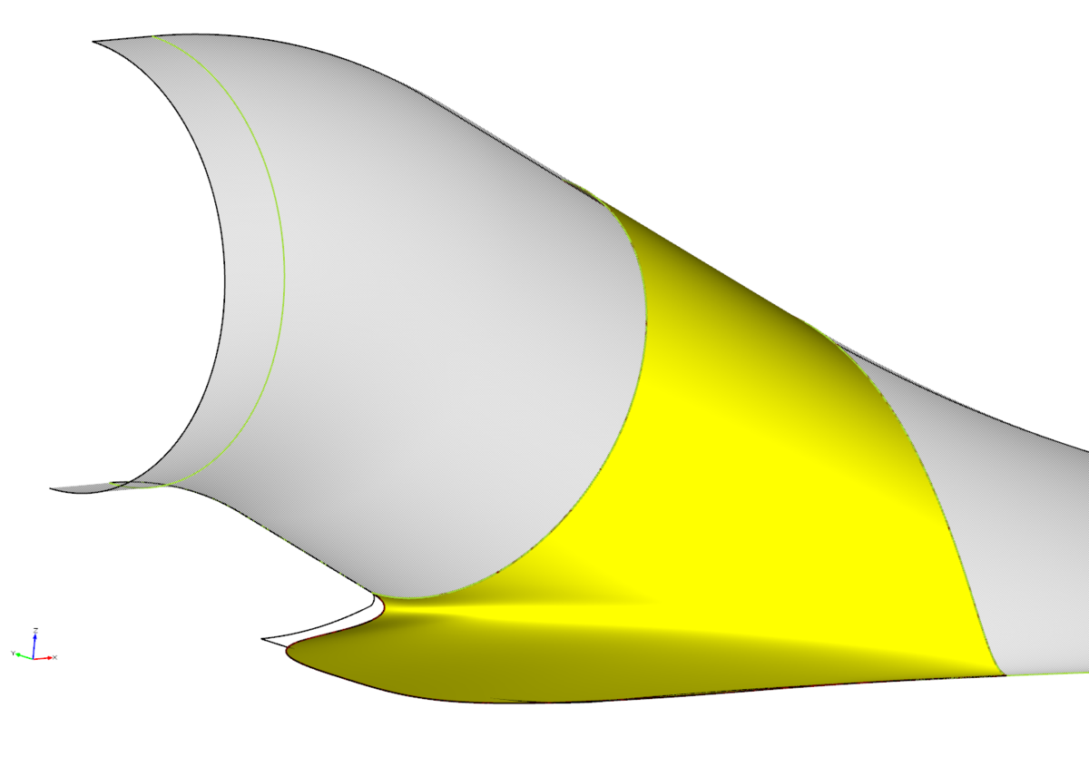
If you replace this rail with a continuous version that looks somewhat like this, the surface quality already gets much better:

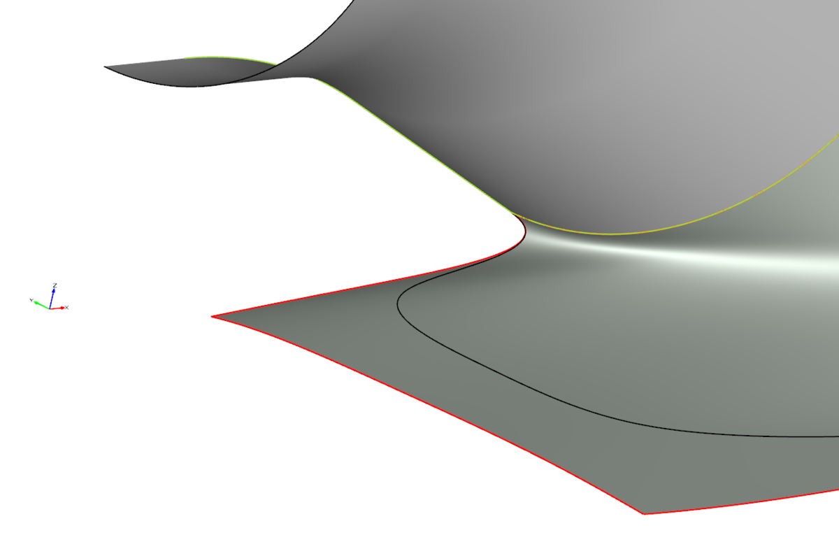
In a BRep, you can now simply extend this surface and trim it at the symmetry plane:

It is far from perfect, but hopefully a good starting point for you...
Cheers,
Heinrich


Ship Hull Form Optimization
in Variation & Optimization
Posted · Report reply
Hi Rizuan,
I recommend you start by looking through the tutorials and samples related to hull design. Which software are you planning to use for CFD?
Best regards,
Heinrich