


Mr. Carsten Fuetterer
-
Content Count
168 -
Joined
-
Last visited
-
Days Won
3
Posts posted by Mr. Carsten Fuetterer
-
-
Hi,
remove the wmUNSET command.
I think your path is wrong. you typed
/home/OpenFOAM/OpenFOAM-2.3.1/etc/bashrc
instead of
/home/alasdair/OpenFOAM/OpenFOAM-2.3.1/etc/bashrc
or can you post the installation path of OpenFOAM
-
Hi,
can you try to move the source command
. /home/carsten/OpenFOAM/OpenFOAM-2.3.0/etc/bashrc
in front of
. $WM_PROJECT_DIR/bin/tools/RunFunctions
-
Hi Alasdair,
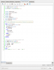
the first lines of your Allrun script should look like:
#!/bin/sh
cd ${0%/*} || exit 1 # run from this directory

chmod +x Allrun.pre
. /home/carsten/OpenFOAM/OpenFOAM-2.3.0/etc/bashrc

# Source tutorial run functions
. $WM_PROJECT_DIR/bin/tools/RunFunctions
I just realized that the source command does not work, instead you should use the dot :
use
. /home/carsten/OpenFOAM/OpenFOAM-2.3.0/etc/bashrc
instead of
source /home/carsten/OpenFOAM/OpenFOAM-2.3.0/etc/bashrc
I hope this works for you
-
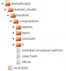
hi,
could you please post the stdouterroroutput.redirect file which you can find in /manual_results/baseline/computation/?
This is the first file you should check if something is going wrong.
cheers
Carsten
-
Hi,
physically I think there should be a bigger pressure in the tank to achieve this. Therefor you maybe have to initialize the air in the tank with a bigger or lower pressure.
best regards
Carsten
-
nice job :D
-
Hi,
this sounds like an interesting project.
But for us it is a bit difficult to understand, where you problem is. Maybe it would be more helpful if you could upload you geometry if it is possible or make a sketch.
best regards
carsten
-
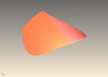
Hi,
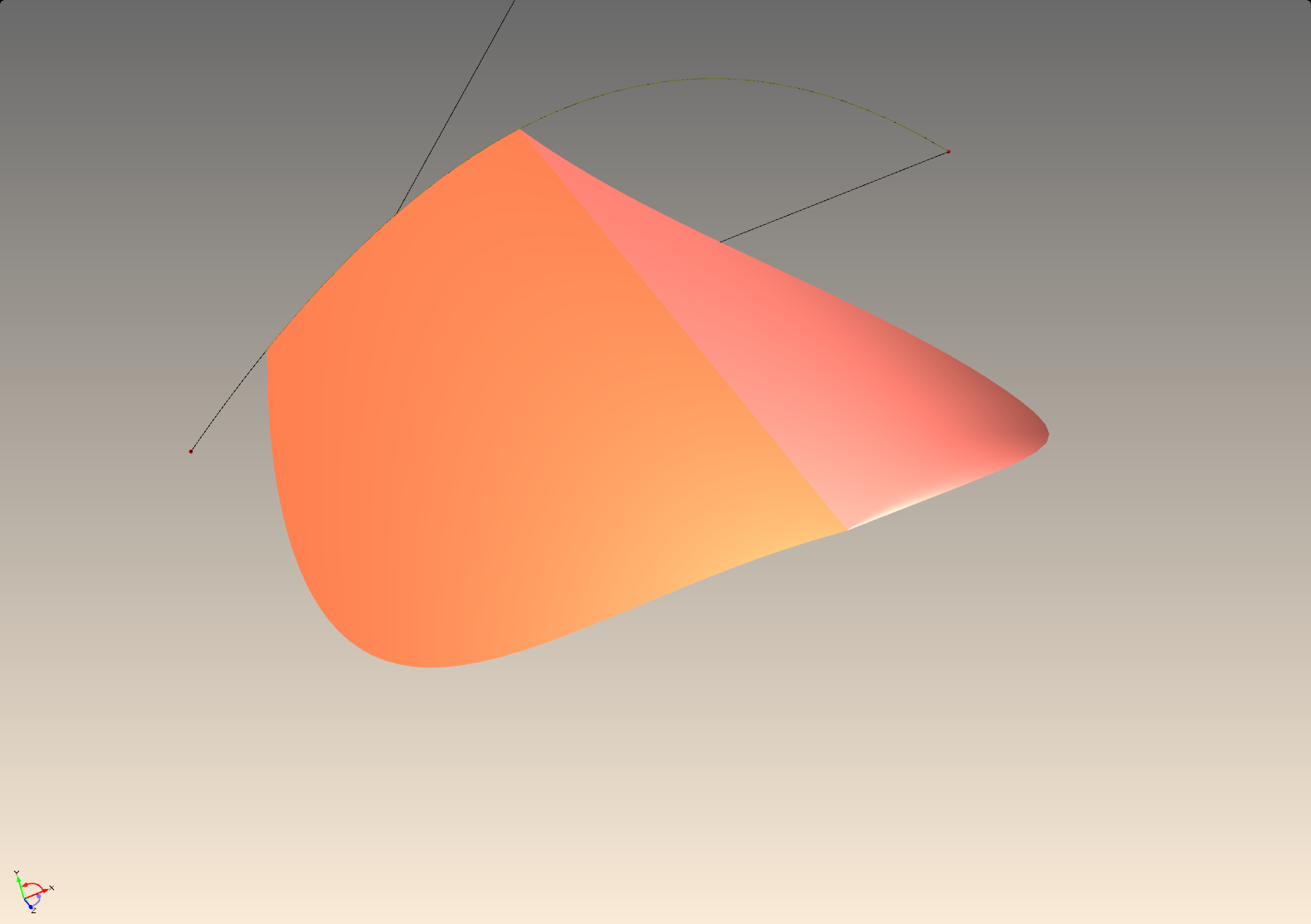
I created an example and posted it here.
I hope this could help you in your design process. It is an watertight model.
If you want to have fillets, you should wait for our next major release, then it will be more easy to do this.
If you have more questions, don't hesitate to ask them.
best regards
Carsten
-
Hi,
attached is an example of a part of a mixing section.
Following design variables can be varied:
- Number of Revolutions
- Number of Nubs
- Nubs Height
- Nubs Width
- Nubs angle (varied by x parameter)
The design process is as follows:
- create cylinder hub
- crate helix
- create Nub
- periodically repeat the Nub along the helix path
- cut solids
Have fun with the model
cheers
-
Hi,
I have to ask some of our Shipflow experts, if this is possible, next week.
best regards
Carsten
-
Hi,
welcome to this forum. I'm not an expert in the cfd simulation of ships, but I don't see a problem there.
I know that the cfd calculation of more ships is possible in Starccm+ and should be also possible in OpenFoam. I don't know about the capabilities of Shipflow.
What cfd program do you want to use?
The modeling process in FFW of two ships is of course also possible. You can take on ship create an image of it and translate it, or you can create two different ships as well.
It is also possible to evaluate the result values of different ships.
Sounds like a heavy but interesting cfd calculation and project :-)
best regards
Carsten
-
Hi,
I created a top entry Mixer which is suitable for high viscous and non newtonian fluids which are sensitive in terms of shear stress.
With the fully parametric model and the easy connection to cfd softwares the mixer can be optimized and adapted to different mixing tasks.
have fun with the model
cheers
Carsten
-
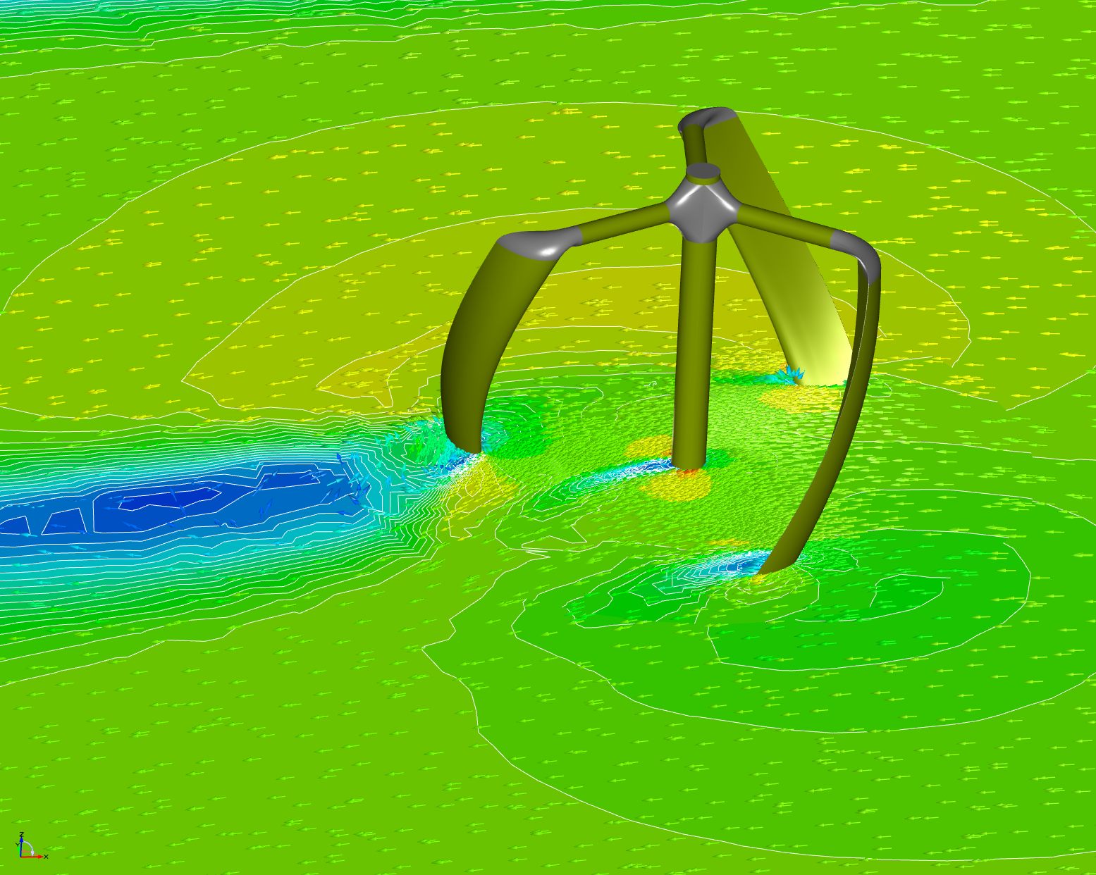
Hey,
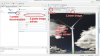
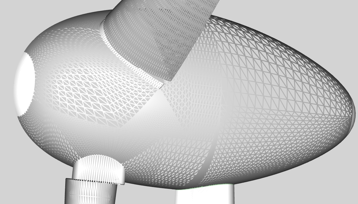
attached is an example of a vertical axis wind turbine, modeled in CAESES. It is fully parametrized, so that an optimization with an external cfd tool can easily be executed.
The shape can be varied from straight blades up to blades that are twisted around the vertical axis (helix). The helix shape helps to minimize the effects of uneven distributed forces along the axis and during the rotation. As a result the VAWT will oscilate less which makes it more robust.
Further design parameters:
- pitch
- camber
- camber position
- chord length
- radius
- mid radius
I created a simple cfd calculation with STARCCM+ to show some post processing functionalities.
Have fun with the model
cheers

-
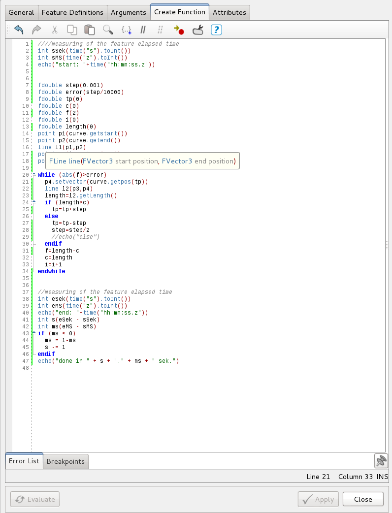
Hi,
in this post is just a little add on to measure the elapsed time of a feature. This can be helpful to optimize it.
cheers
Carsten
-
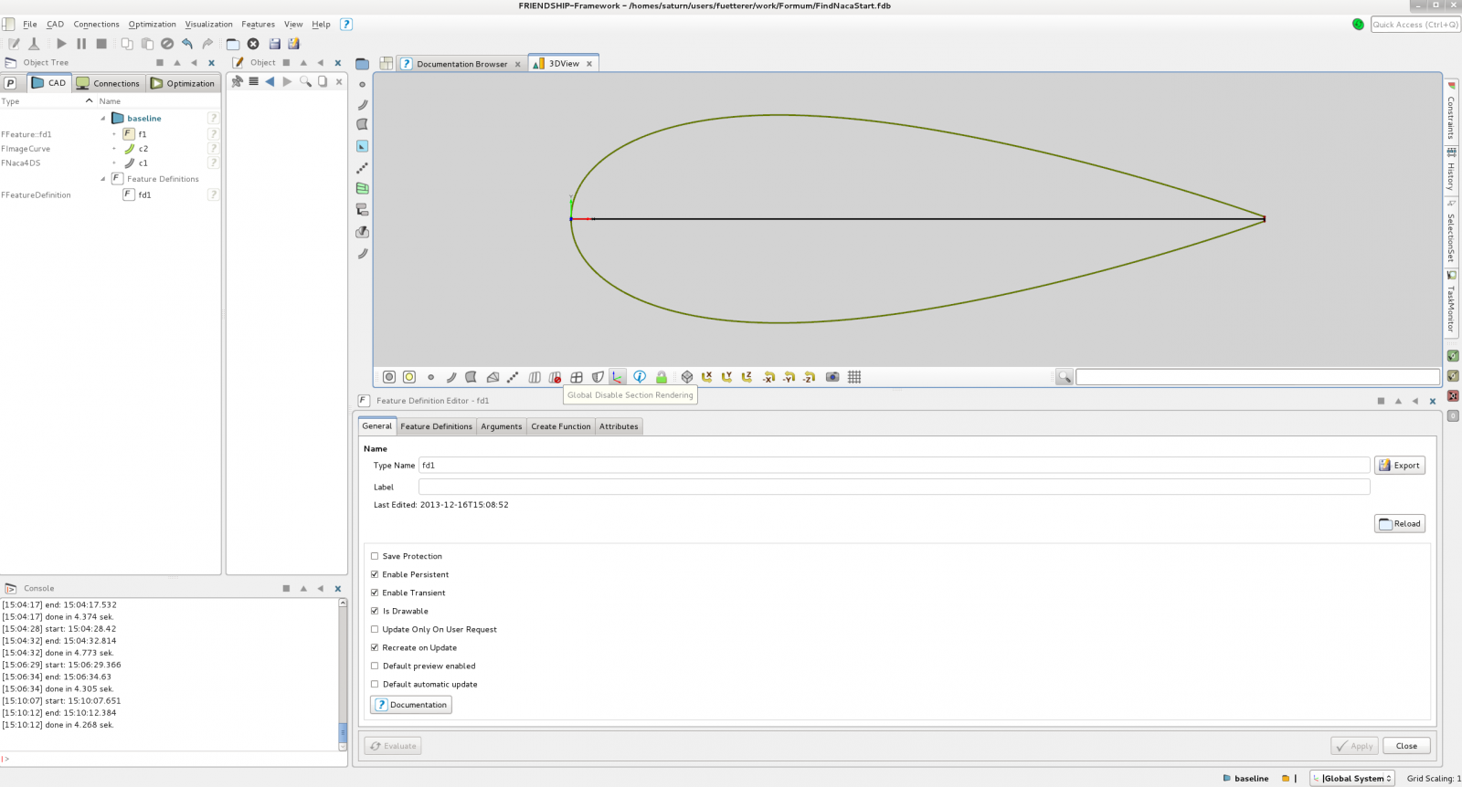
Hi,
in some cases it is hard to get the exact position of the leading edge of a NACA profile, because the t-parameter (curve parameter) is not at 0.5 anymore. That is why I wrote a small feature which finds the t-parameter for the point which has the longest distance to the trailing edge.
Furthermore I included a few lines in the feature to measure the elapsed time. This can be helpful to optimize your feature. (Thanks Stefan for this.)
regards
Carsten
-
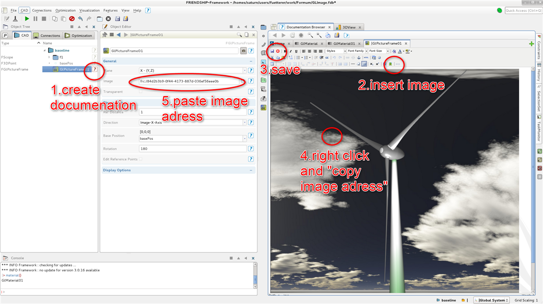
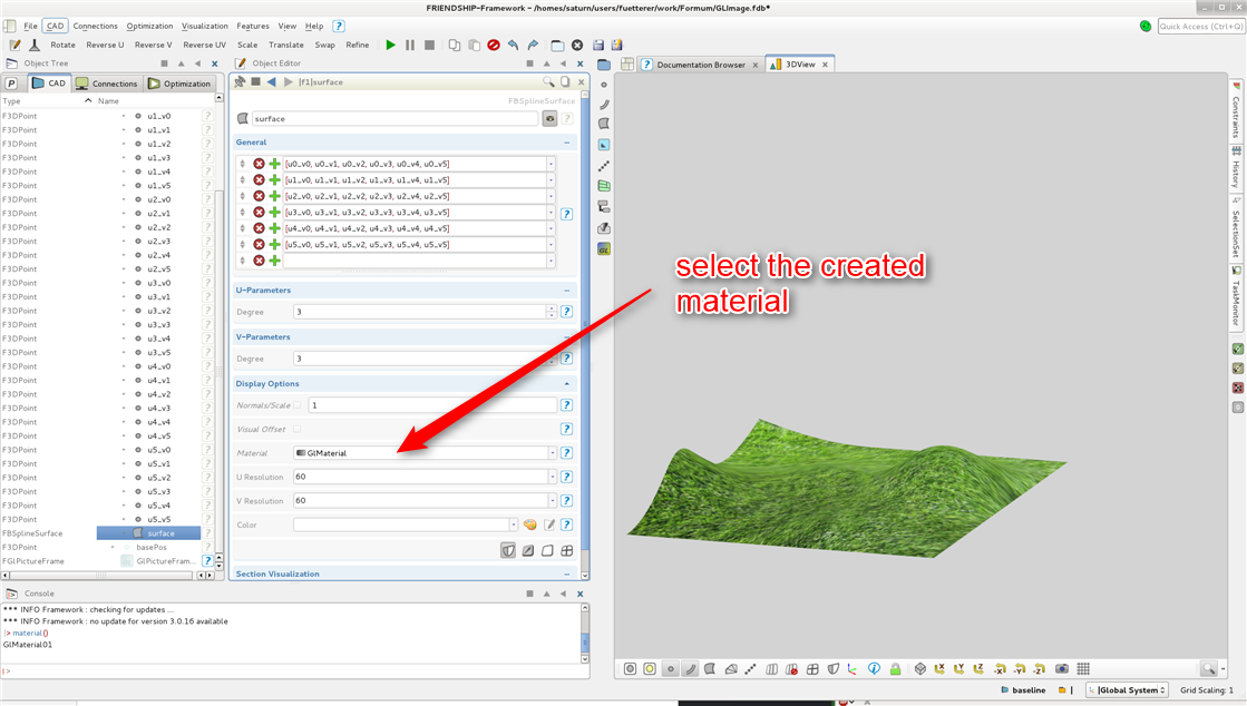
Hello,
when using GLPictureFrames and GLMaterial, the default settings are, that images are referenced with a path to your system.
When the project is used on a different system, then the information to location of the images are missing, that is why it is a good idea to save the image in the project.
To do that, you have to
- save the images in a documentation
- right click on the image in the documentation and "save image adress"
- use image adress as the path
You can do this for GLPictureFrame as well as for GLMaterial.
In generell GLMaterial can be used to give surfaces a customized textures and GLPictureFrame for example for Backgrounds.
Requires CAESES-FFW 3.0.16 or newer.
Regards,
Carsten
-
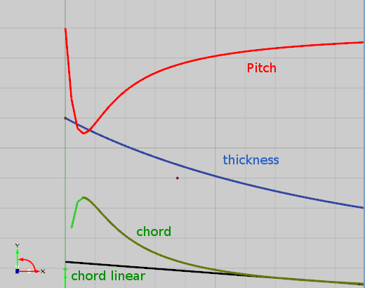
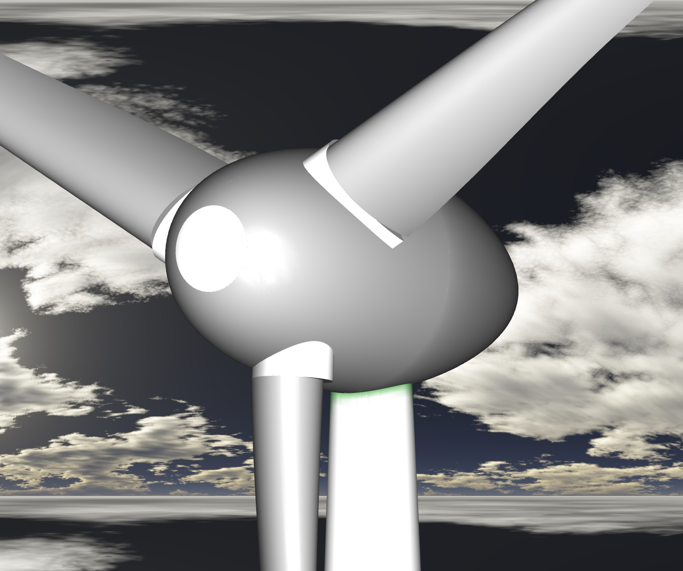
Hi all,
attached is an example of a wind turbine. This surface model is based on empiric [burton, 2011. Wind Energy handbook] radial distribution of chord and pitch, which are dependend by the
- Design Angle of Attack (AOA)
- Lift Coefficient
- Radius
- Tip Speed Ratio
The Lift Coefficient can be determined, by empiric equations (0.1*(AOA+4°)[burton,2011]), taken from tables or can be determined with other ways. The Profile based on a cambered NACA-4ds.
The Tip Speed Ratio is given by (Pi*D*n_R/v_w), where n_R is the rotational speed, and v_w the design wind velocity.
The angle of the rotation can be varied as well, to avoid contact of the blades with the shaft in stormy conditions.
A design attribute of this wind turbine is, that the maximum chord length is modeled up to the hub, which should enlarge the total power coefficient, because of less speration losses. This is reached with a little stationary wing part at the hub, where the design pitch angle should be that from the design wind velocity and tip speed ratio.
Furthermore this example shows tip and subsurface modulation.


-
Hey,
attached is an example of a pipe heat exchanger which is one of the key units in energy and process engeering.
For the modulation mainly solids were used, to cut the bunch of pipes from the main frame. Check also the feature definitions, to see how to write objects in lists and create one solid from the every single object in that list.
If you have many solids like in this example and you want to do boolean actions, it is important seperate the different solids to avoid errors. Check therefore the small groups of solids.
regards
Carsten
-
Hi Amitava,
please refer to this post where the connection to STARCCM+ is shown. It is more an example for process engineering, but you can get the idea of how to couple STARCCM+ to FFW.
Please let me know if it was helpful.
best regards
Carsten
-
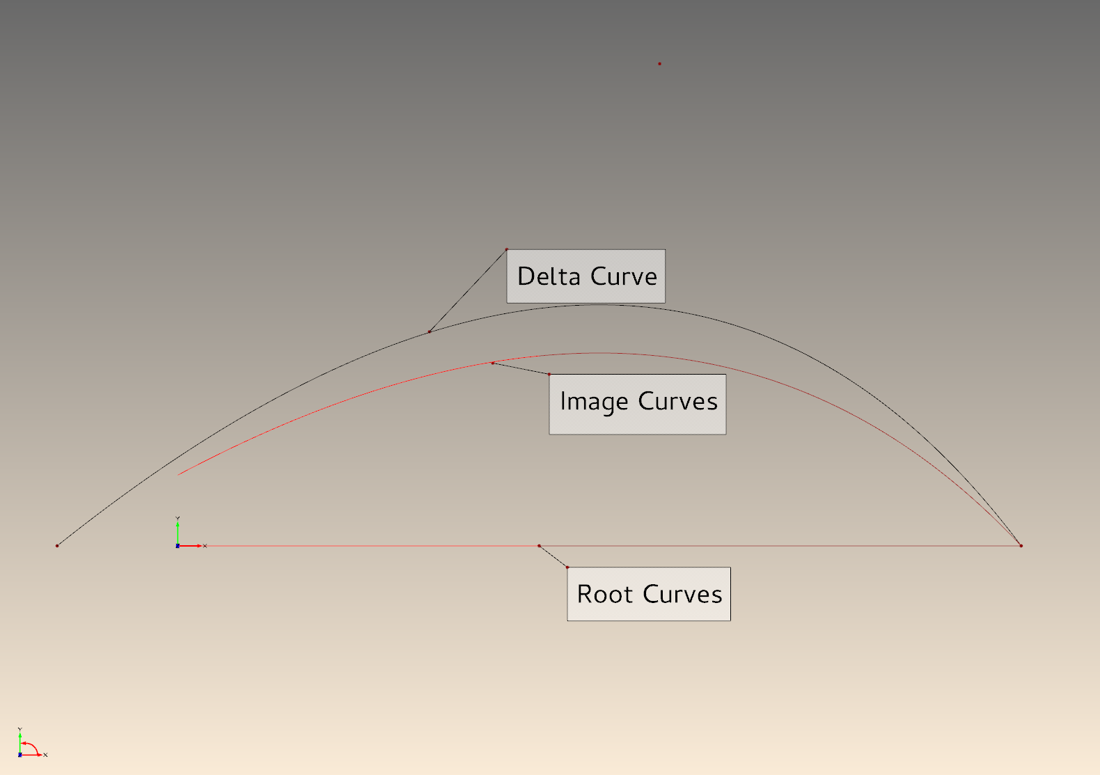
Hello,
here is a little example that shows a DeltaShift with one DeltaCurve for multiple root curves. This is really useful, if you have two lines created and want to apply a curvature to them without changing the definition of each line.
Carsten
-
Hello,
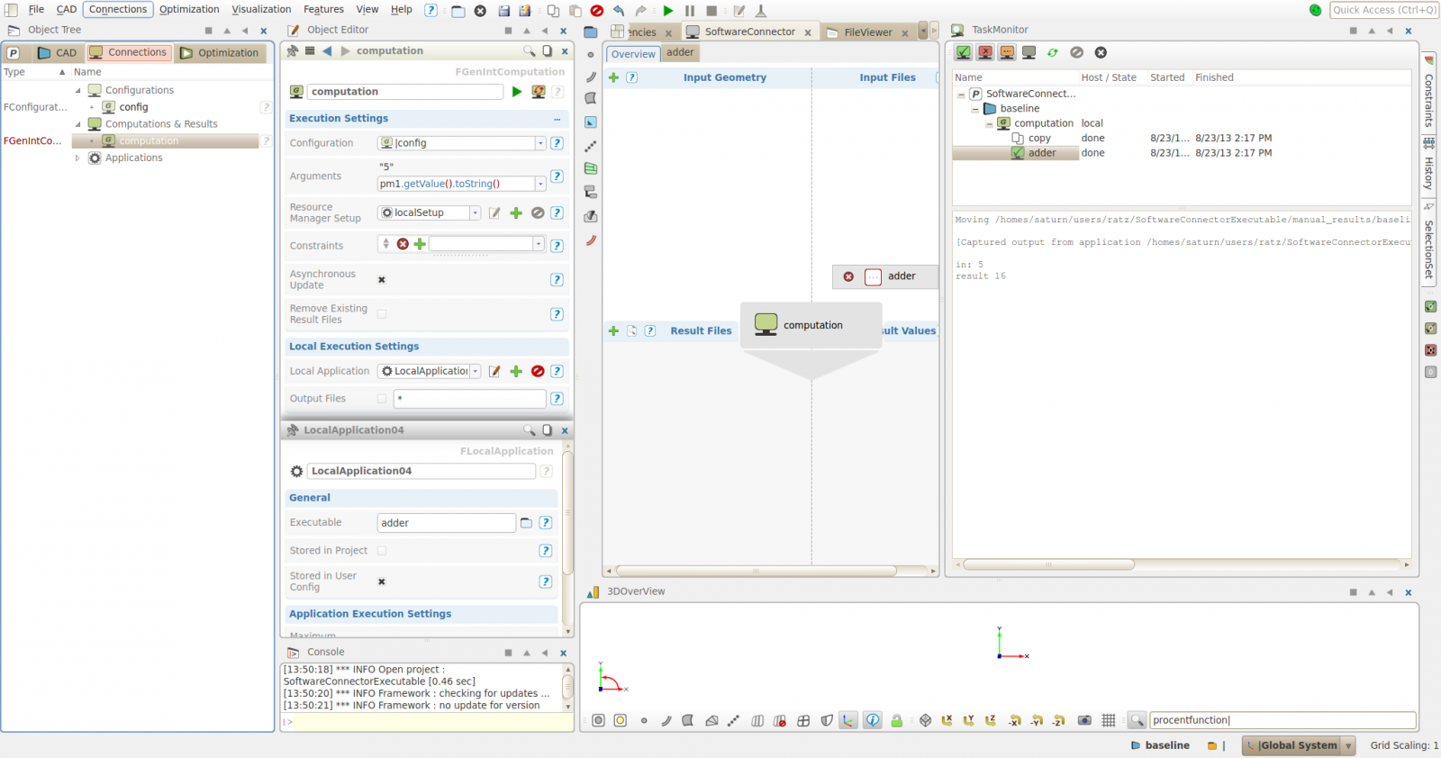
This guide will show you how you can connect OpenFOAM to CAESES-FFW or any other application.
Using the Software Connector, you need a executable of the Local Application. If you want to start this application with a script, do following:
- create on your Desktop a text file with the execution command of your desired external application (OpenFOAM) and save as 'adder'
- add the script 'adder' to your Input Files in the Software Connector and 'double click' it, so that it is copied into the project and is converted to a Template
- click on computation (in the center of the Software Connector)
- create a new Local Application (using the green + symbol)
- define the Executable: write down the name of the Template 'adder' which you have imported in the Input Files
- run the Computation (click on the play button)
- check the result in the Task Monitor (on the right side shaded widget) and click the green button in the top left corner to show the finished computations
Attached is a little example which shows this. In this example the script adds the Argument of the computation (which is defined by the Variable pm1) to a defined Variable in the script (addend).

Best regards
The Team of FRIENDSHIP SYSTEMS
-
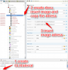
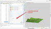
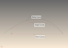
ok,
then please post the error message. You can find this file in your project directory. See therefor the attached picture.
best regards
Carsten
-
Hi Amitava,
I prepared a little documentation to integrate STARCCM+. I can upload it next week.
best regards
Carsten
-
Hi James,
please try to start CAESES from the terminal. This helped in my case.
Please post the stdouterroroutput.redirect file if there are still errors.
cheers
Carsten


Free OpenFOAM GUI
in Software Connections
Posted · Report reply
do you have
?