


Mr. Carsten Fuetterer
-
Content Count
168 -
Joined
-
Last visited
-
Days Won
3
Posts posted by Mr. Carsten Fuetterer
-
-
Hi Lu,
to be honest, it seems to be relatively difficult, to change the number of rims with some sort of transformation. Changing the shape of the rims should be easy with our freeform deformation.
So if changing the number of rims is really important, you should think about creating a fully parametric model of the wheel.
best regards
Carsten
-
Hi Lu,
maybe you can start simple and create a imagetrimesh from your imported stl. And use a scaling transformation to change the radius. Attached is a sample file. In the meantime we take care about the license.
best regards
Carsten
-
ok in that file are no signifcant errors. Did the solver run?
-
Hi Christop,
could you at least post or send us the shell script? It seams to me that you are not meshing.
best regards
Carsten
-
Hi Christoph,
can you post one of the stdouterroroutput.redirect files, which are located in the design directories.
Did you run the baseline first? Did you got your objectives? Can you find any results in the design directories?
best regards
Carsten
-
Hi Alaric,
you have to set set a parameter like pressure drop from your cfd calculation in the evaluation section of the design engine. This parameter parameter must be set up in the lower right section of the software connector.
Does this helps you?
best regards
Carsten
-
Hi guys,
today I want to share with you my latest feature which creates a bounding box for your OpenFoam internal flow geometry.
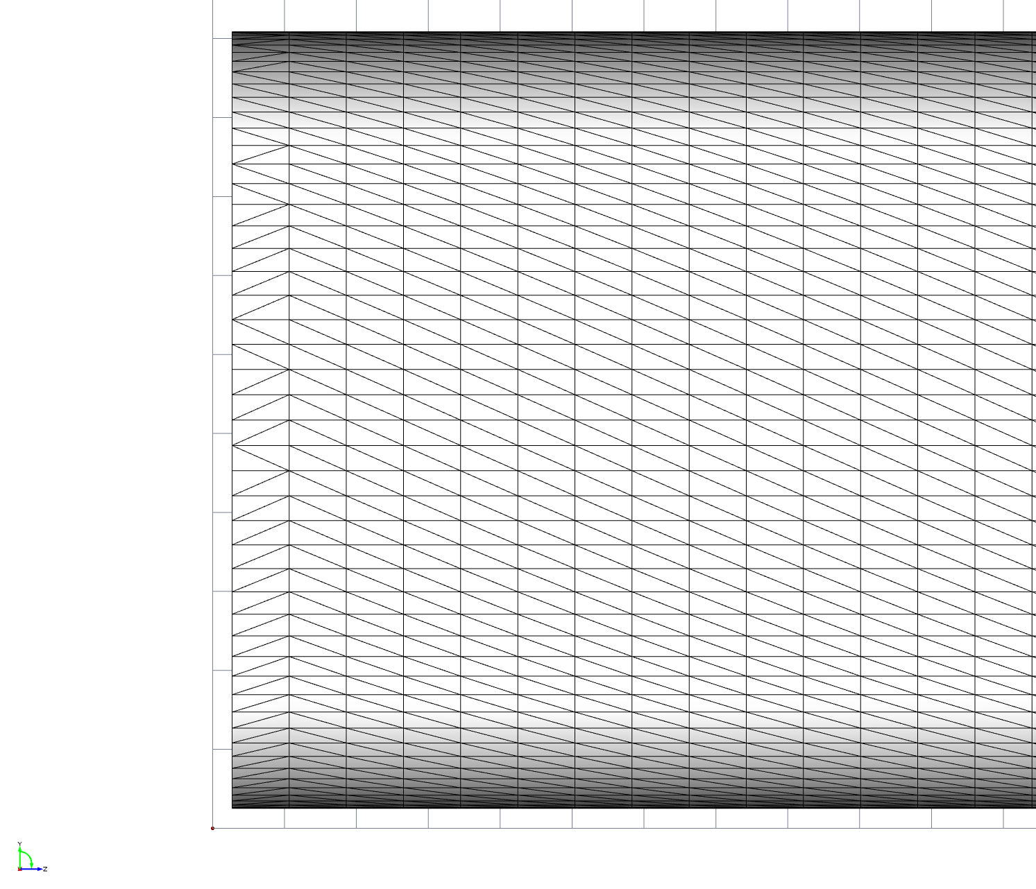
The idea came, when I struggled with SnappyHexMesh because the edges of the boundaries where not captured correctly, which resulted in a bad prismlayer mesh like this: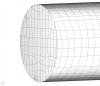
(image 1)
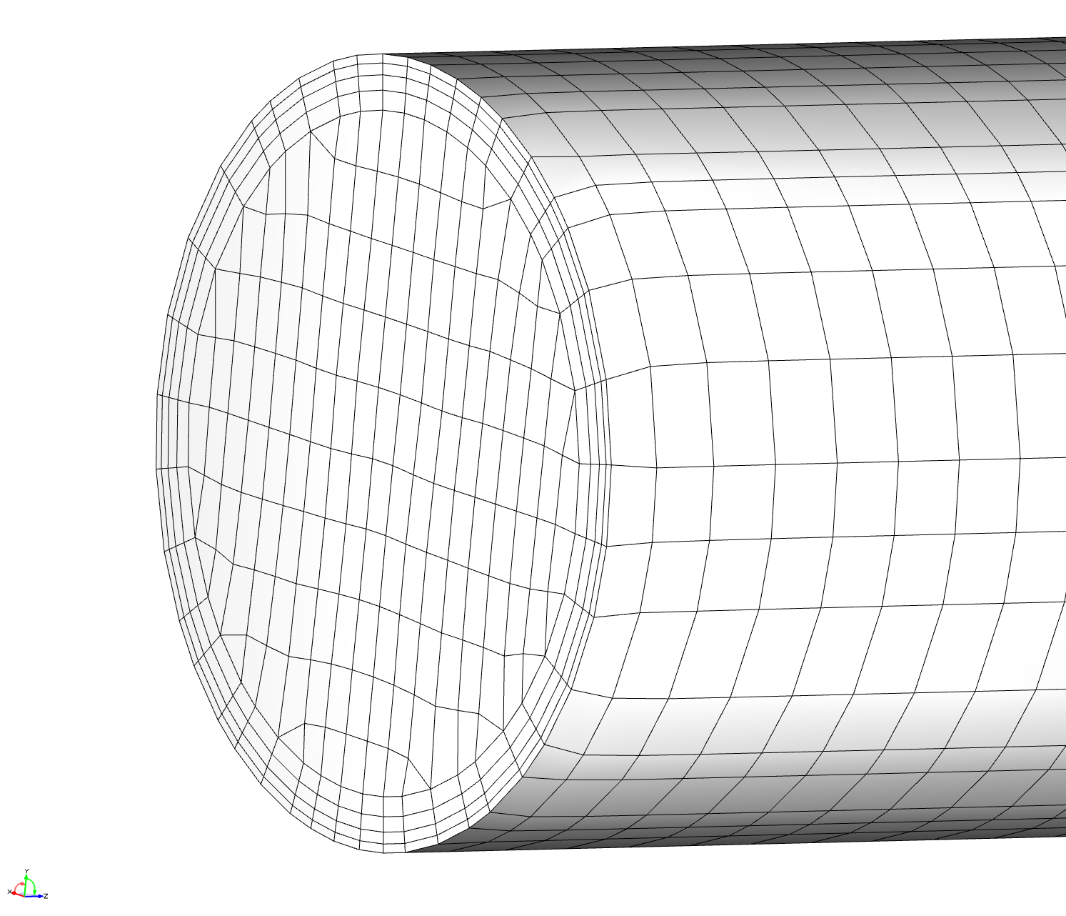
I found out that the reason for this, was the bounding box, where the inlet and outlet boundary do not lay within the first layer of the box like this: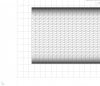
(image 2)
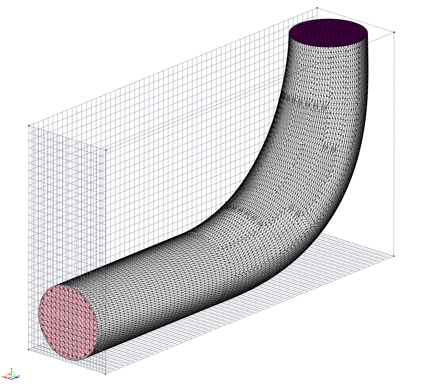
So I created I bounding box which automatically adjusts with the changing geometry. It calculates the maximum and minimum positions and creates the bounding box with a user specified offset. A nice setup looks like this: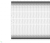
(image 3)
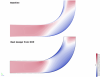
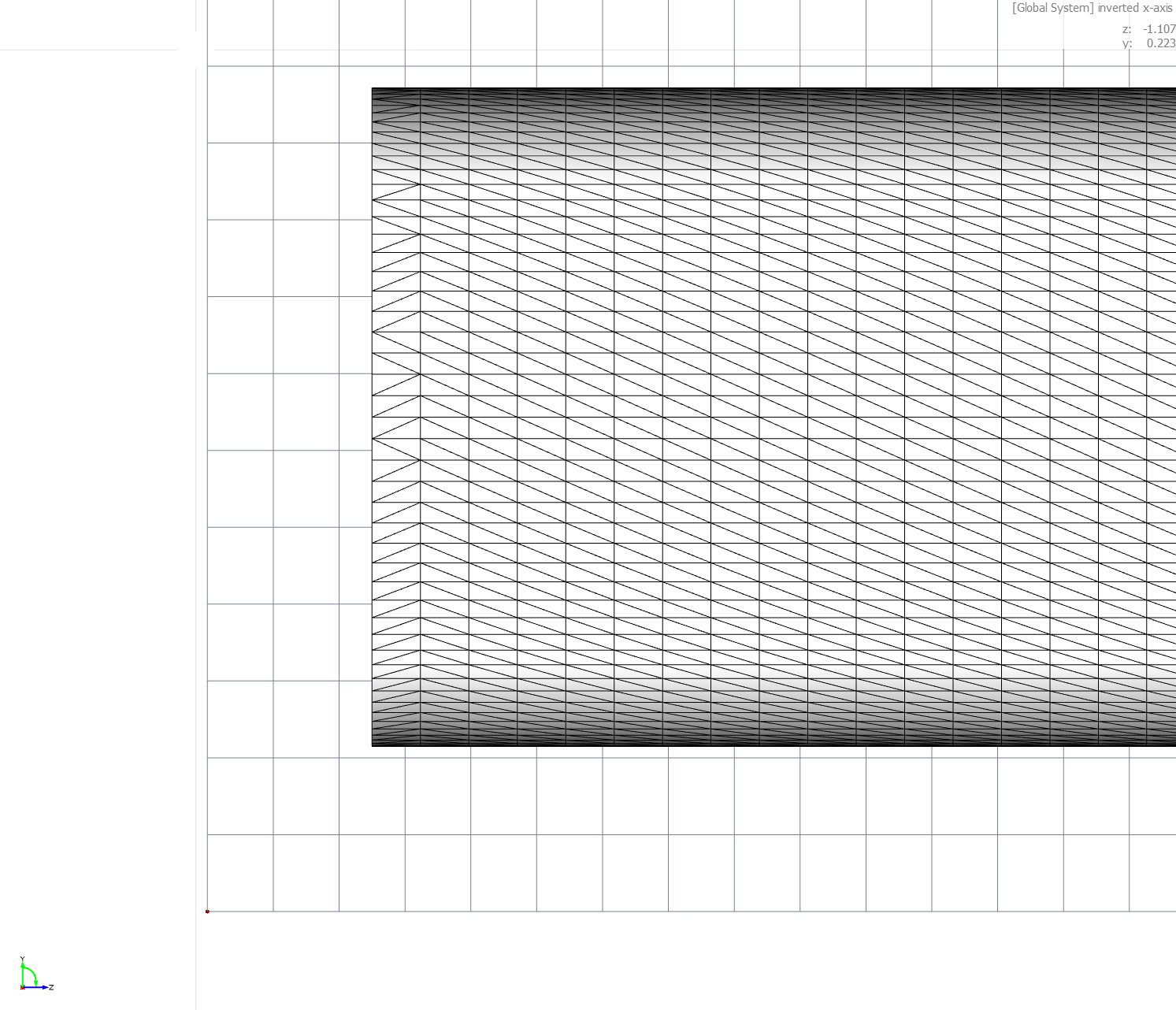
This setup produces a nice volume mesh with clean prism layers: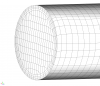
(image 4)
The complete bounding box, where the subdivision in x, y and z coordinates can be specified, looks like this: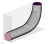
(image 5)
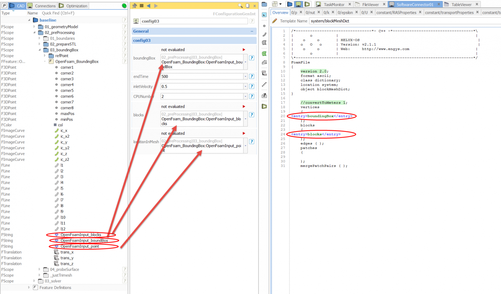
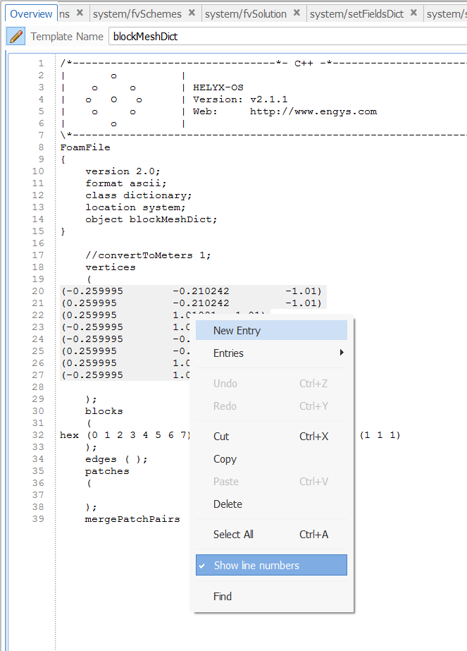
The following picture shows how to connect the BlockMeshDict with the bounding box feature:
 (image 6)
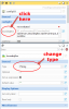
Remember that you have to create an entry for the vertices by selecting these, right click and select new entry:

(image 7)
This creates a new entry in your config dialog. There you have to change the type to FString:
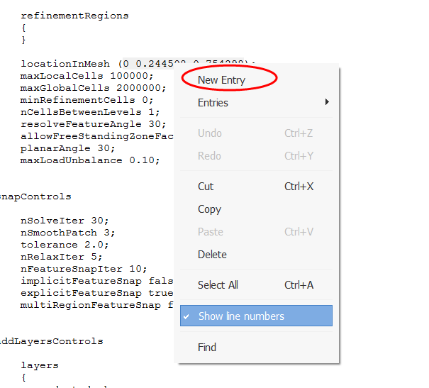
 (image 8)Do the same for the line where the blocks are defined (see image 6).Now you have create a new entry for the point in mesh, which you can find in your SnappyHexMeshDict. Follow the same procedure, but just mark the three coordinate like this for a new entry:
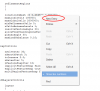 (image 9)
That's it. This is just a first version of the feature. I could imagine to write another feature for the creation of the bounding box for external flows, where you could specify different patches within the BlockMeshDict.
Of course you are also welcome to post your features here in the forum.
Attached is the feature and an example how to use this feature with a complete software connector. This example by the way couples OpenFoam for Windows with CAESES.
Have a nice day
Carsten
-
Hi Bram,
I never tried this tutorial on Windows. When you run OpenFoam on your mashine, do you have to call some environment variables?
Can you provide us the "stdouterroroutput.redirect" file of the simulation?
best regards
Carsten
-
Hi,
I want to share with you a feature, which writes all parameter and design variables into a file ("allParameter"). In the arguments you can decide if you want to include parameter or just use the design variables.
The feature also creates an .fsc ("setParameter.fsc") file. This can be used to create a specific setup from the file. To open the fsc file in gui mode just go to File->Execute Script.
cheers
-
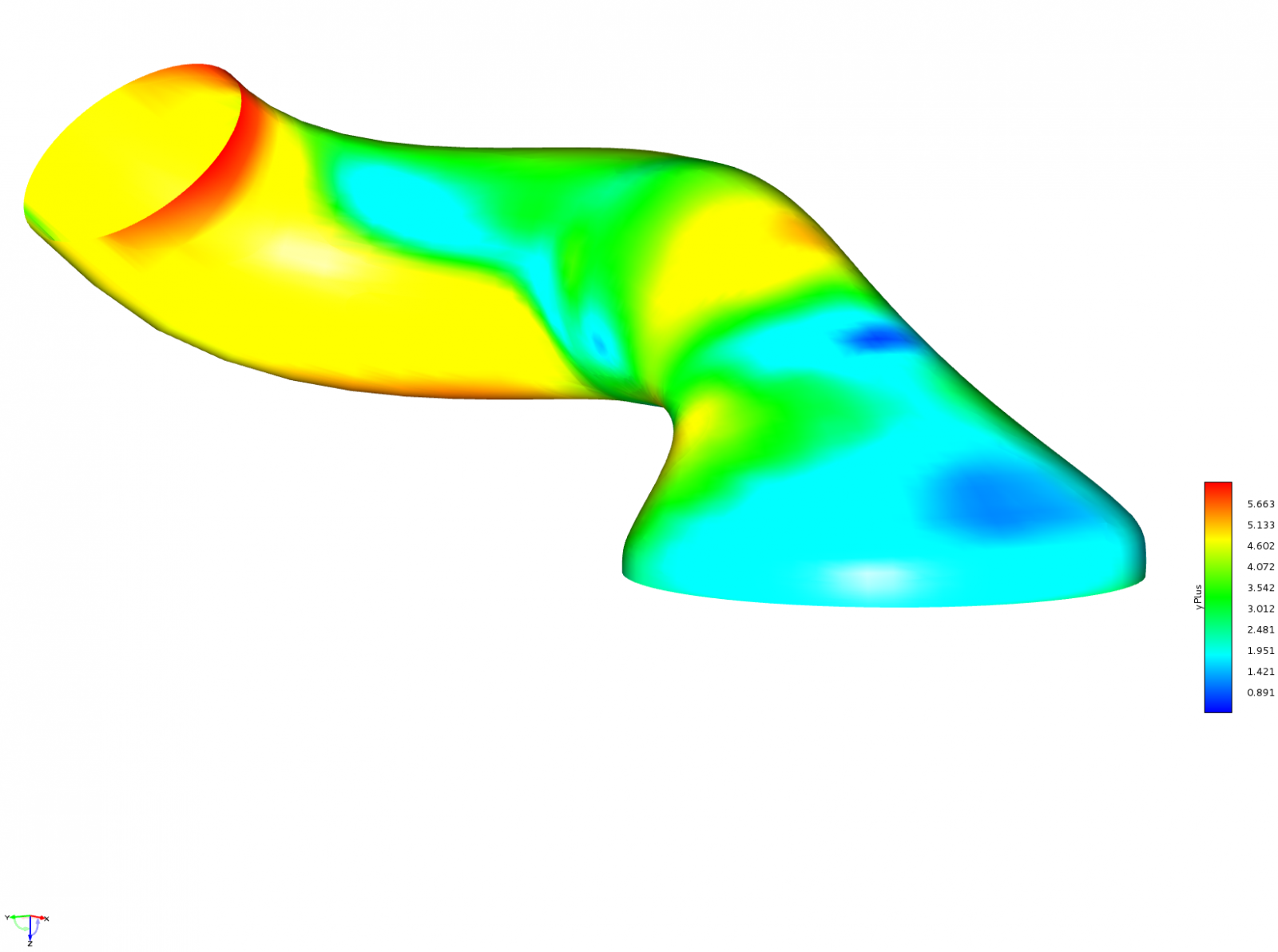
Hi,
the usal way of visualizing data from OpenFoam is to create a file like foam.case in the calculation directory and to import this file. The problem is with this method, that only the data of the internal mesh are displayed in CAESES and that you do not have the values of the boundary faces.
To see these values you can export your OpenFoam data to VTK. This is done with follwowing OpenFoam command:
foamToVTK -latestTime
With this command a new folder called VTK is created with the VTK files of all boundaries and patches. Theses different files can be imported into CAESES and values like Wall Yplus or pressure can be displayed.
Have a great start into the week :-)
Carsten

-
yes, all optimization engines minimize by default.
-
you just choose the drag as an evaluation and set it as objective. There should be just one objective.
cheers
-
Hello Henrik,
did you run a sobol or a sensitivity analysis by dakota first? I would do this to scan the design space. Then you could try the Local Optimization Efficient Algorithm by Dakota. This is a local search with a surrogate model (response surface). It can use the results of the DOE to build a first response surface. It will optimize internaly on this and will calculate the best design and so on. I had some good results when I set the samples per iterations to zero. This means it will calculate just one design of the response surface.
But this is just one way to optimize.
Does this gives you a first idea?
cheers
Carsten
-
Hi Maria,
sorry I used a wrong CAESES version. Here you can find the propeller with the current release (CAESES 3.1).
best regards
-
Hi,
I created for you a watertight geometry which you can export to use in Ansys. This is the usual way, we export geometries. Take a look and try to understand.
cheers
Carsten
-
Hi,
I recorded a short video to show how boundaries of a trimesh can be colored. When you export this trimesh as multibody STL, each colored surface is written as an own patch in the stl.
I hope this helps you.
Carsten
-
sounds great. Feel always free to post your questions here :-)
cheers
Carsten
-
does it work?
-
could it be that you use Ubuntu 14.04lts? and that you therefore had to compile OpenFoam for your own? Then you have to write
of230
to load the bashrc.
So try to insert "of230" at the second position of the Allrun script. Mabe you have to adjust the version number.
Maybe you can have a look on your profile ~/.bashrc file
-
hi jussi,
i get the same result. I try to get a solution today.
-
great!!
-
no problem,
please do not use "source" instead use "."
-
ok I see the mistake.
please write:
export FOAM_INST_DIR=/home/alasdair/OpenFOAM
foamDotFile=$FOAM_INST_DIR/OpenFOAM-2.3.1/etc/bashrc
[ -f $foamDotFile ] && . $foamDotFile
-
ok then you have to do what Konrad Lentz posted in the 9th post


OffsetCurves perpendicular to a surface using setThicknessCurve
in Feature Programming
Posted · Report reply
Hi Bodo,
yes, this functionality is right now just implemented for both sides true and used for impeller design. I have to ask our developers if it will be available in future releases for any offset curve type.
In the meantime, you have to create to create a feature, which creates points which are normal to the surface on a surfacecurve and interpolate them. As a start you can use the feature curve normal point.
best regards
Carsten