


Mr. Carsten Fuetterer
-
Content Count
168 -
Joined
-
Last visited
-
Days Won
3
Posts posted by Mr. Carsten Fuetterer
-
-
Hi Suraj,
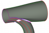
all functions should all be between normalized hub radius and 1 in the x-coordinate. Because with the blade object you will create the blade normalized (radius ==1). The y-values don't have to be normalized.
Also you can refer to the propeller sample.
best regards
Carsten
-
Hi Haipeng,
you have to write a feature inside the project, which writes a file. This can be the code for the feature:
ffile file(getResultsDir()+"/"+filename)
if (!file.openWrite())
  echo("Failed to open file \"" + file.getAbsolutePath() + "\" for writing")
  break()
endif

// use file.write() or file.writeLine() to write to the file.

file.writeLine(""+p:x+"\t"+p:y+"\t"+p:z)


//close file when done with it
file.close()
To write this code I simply used the feature templates.
Then in the fsc script you have to write a line:
exportFile.run()
This will update the feature and trigger the export.
best regards
Carsten
-
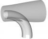
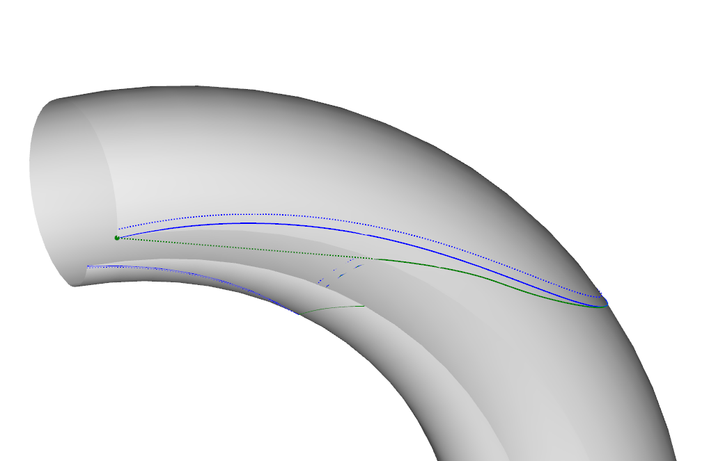
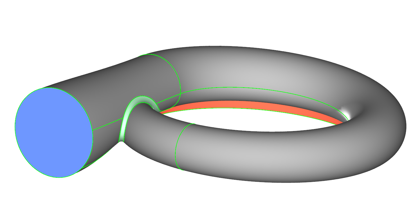
Hi Marta,
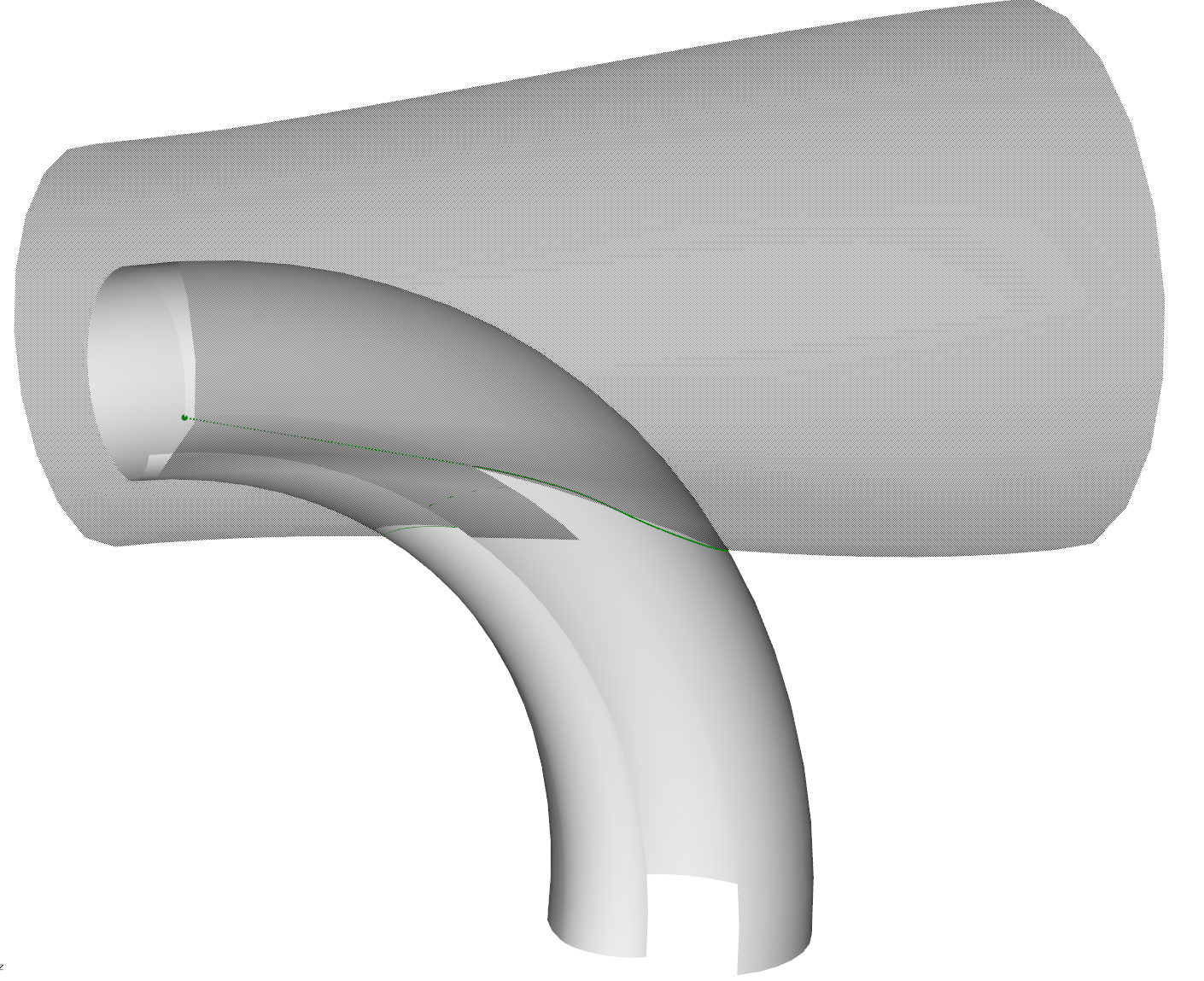
attached is an example how you can model the tongue area. Basically we want to trim the volute and the outlet surface in order to have space for a fillet surface. To do this we follow these steps for each part:
1. create intersectioncurve e.g. volute and offsetsurface of outlet
2. modify the domaincurve of the intersectioncurve. create also an offsetcurve of the new domaincurve
3. create surfacecurve from new domaincurve and a surfacecurve from the offsetcurve, which will be tangent edge for the fillet surfaces
4. create a subsurface from the new surfacecurve
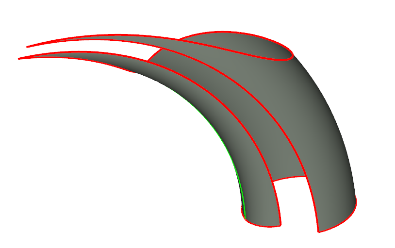
5. put the subsurface into a brep

After you did thtis with both parts it should look like this:
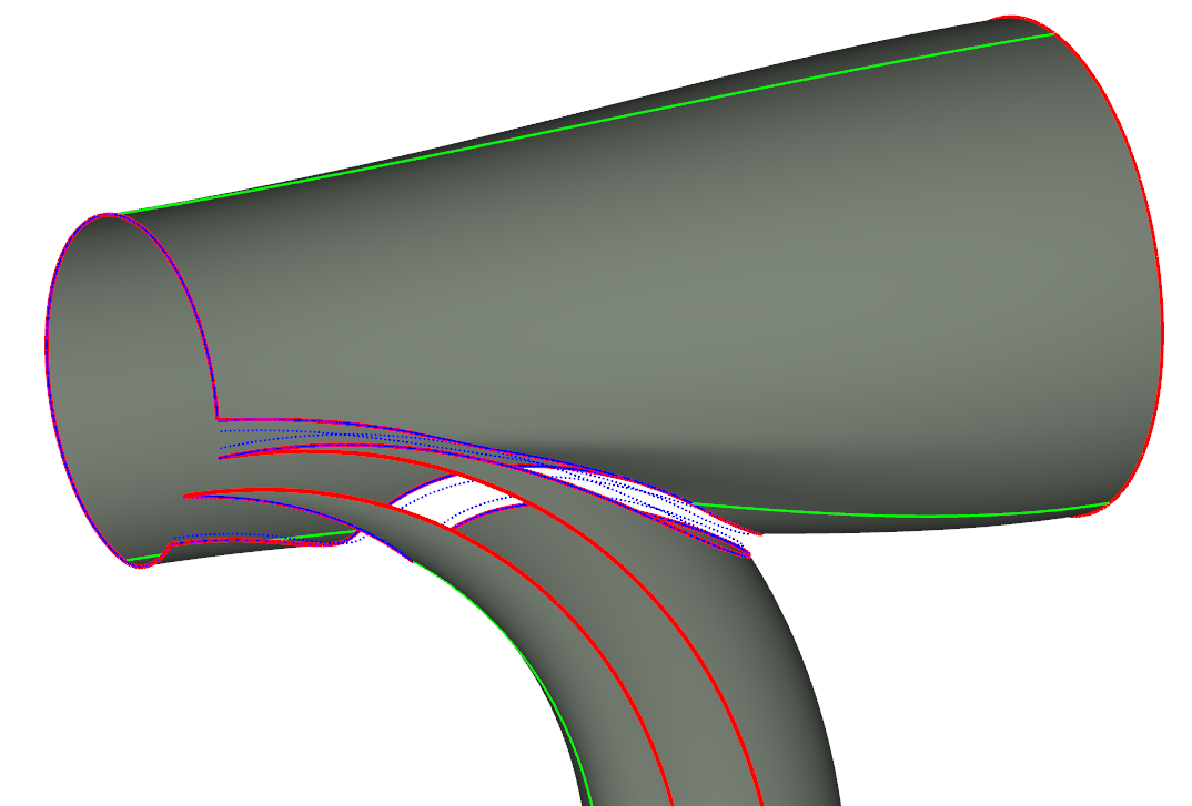
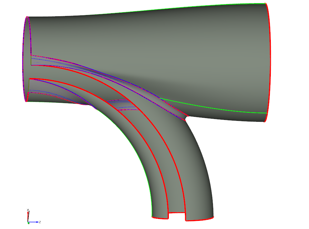
Now you can use the edges and tangent edges to create the fillet surface with a meta surface:

The final results can look like:

best regards
Carsten
-
Hi Fotios,
attached is an example which works with simflow on windows. Let me know if you can adapt your project to it.
best regards
Carsten
-
Hello Fotios,
you can do the following:
- rename the allrun to allrun.bat
- remove the first line: #!/bin/bash
- I am not sure if the source command works, its usually used on linux
- can you start openfoam commands from the cmd terminal like blockMesh.exe?
- extend the openFoam commands with the extension .exe
best regards
Carsten
-
Hi Yanxin,
I can not really tell you whats going wrong. Can you identify some geometry problems for theses designs? In which format do you export the geometry from CAESES?
best regards
Carsten
-
Hi Yanxin,
it looks that these extrem CFD results come from a diverged solution. You can check this by going to the result of one of these designs and check if the mesh is ok or not. What application is it?
best regards
Carsten
-
Hi Fotis,
can you upload the project?
best regards
Carsten
-
we are close, I just installed OF4.1 the answer is
postProcess -func "patchAverage(name=sduct_lightpink,p)"
best regards
Carsten
-
Hi Lorenz,
what is the error messages when you try:?
postProcess -func "patchAverage(sduct_lightpink,p) " -latestTime > pin.dat
cheers
Carsten
-
Hi Lorenz,
this is the typical OpenFOAM version Issue. With each update the control commands change slightly.
But the error message seams clear to me, just write RAS instead of RASModel. You can have also a look into the OpenFOAM tutorials for example the motor bike, to get the correct syntax
best regards
Carsten
-
Hi Alvaro,
from the standard openFoam format we get currently only the volume mesh. To visualize for example the propeller surface, you can use a work around: Create an iso surface, with the velocity of near zero. on this surface you could create an contour plot with pressure for example.
The other way would be to export an extra VTK file with the openFoam utility "foamToVTK". With that you wil get a vtk file for each patch and the volume mesh.
best regards
Carsten
-
Hi Lexi,
I don't know to which picture you are referning in the document.
You can also trim surfaces with the help of subsurfaces or Breps using Projections.
best regards
Carsten
-
Hi Lexi,
If I understand you correctly, I can split a patch surface with an imagesurface. Just restrict the u- or v- domain.
best regards
Carsten
-
Hi Yanxin,
ok it seems that the point [97.4,0,5.4] is at the bulb. You can try to increase the tesselation.
best regards
Carsten
-
Hi Alvaro,
sorry I think this is a Bug in the new Version.
Try to,
-select the Runner
-Go to Local Execution Settings and click on "show more options" (the three dots)
-then toggle "clear Input Directory"
Let me know if it works for you.
best regards
Carsten
-
 1
1
-
-
Hello Yanxin,
I just had a brief view into the project. The error mark does not seem the be a problem. You will always have this error mark along an open edge of the trimesh. The trimesh looks fine.
So I think you can continue.
best regards
Carsten
-
Hi Chris,
it would be nice to find out why the project and trim operation does not work. Maybe the reference point pointed not on the surface? If you could give us the project we could was a look into the problem.
best regards
Carsten
-
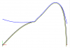
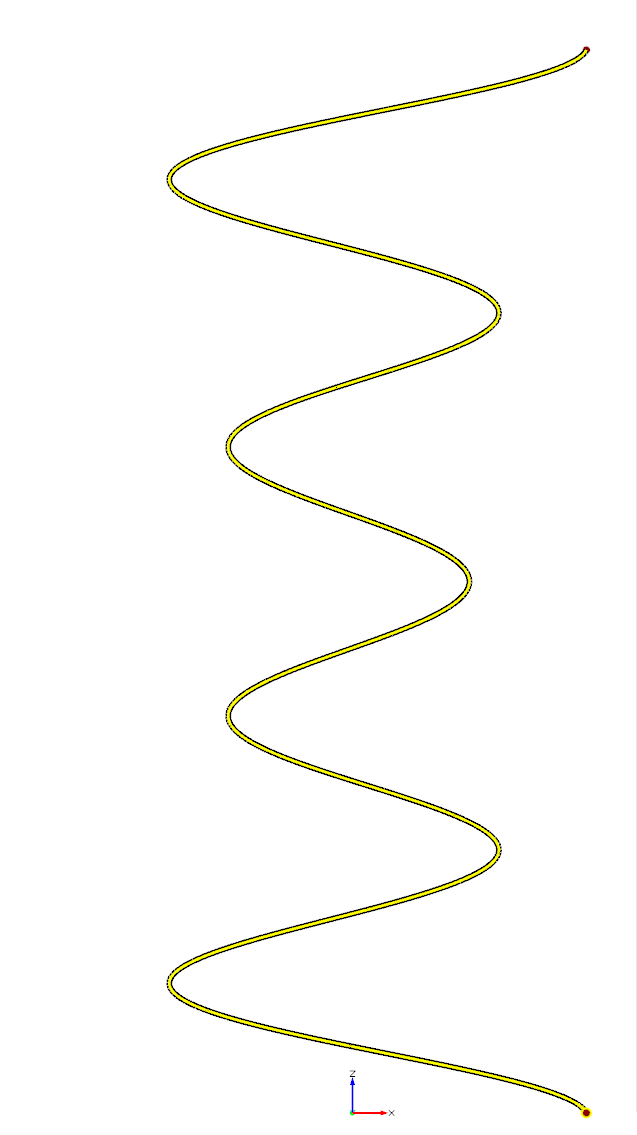
Hi Kevin,
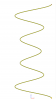
you can use the generic curve and implement the definition of a helix. For the radius, you can define a function, for example a bsplinecurve with 3point. This function can be defined in xy plane, where the y coordinate defines the radius.
Attached is an example for this.
best regards
Carsten
-
Hi Chris,
there is the operation Project and Trim. I guess the interesting part within this operation is the reference point. When you set a reference point the part of the closed projection curve will be trimmed or kept, which is referenced by projecting this point.
Have you already tried this operation?
best regards
Carsten
-
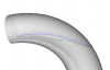
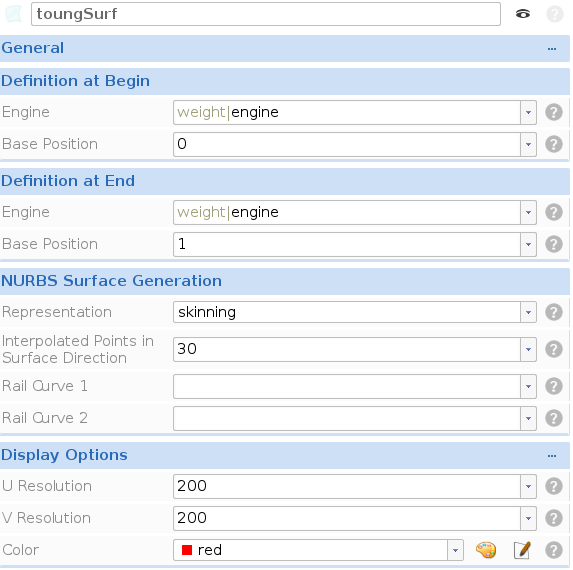
Hi Zheng,
nice project. The idea how you create the intersection curve with the feature is good, but leads to problems. Since the speed of the parametrisation of the volute surface changes in the middle, because you have a polycurve in your crosssection definition, you would have to create much more points in the domain, to approximate the correct domain curve. It is much easier, when you create an intersection curve and then get the domain curve from this withe the command .getdomaincurve().
Also you can create two offsetsurfaces, to get the offset domain curves. Attached is an example how you can do this.
After you have modified the domain curves to your needs and created a nice surfacecurve, you can also use this surfacecurves as rail curves in your metasurface. This will make sure, that the metasurface exactly matches this surfacecurves.
If you have further questions let me know.
best regards
Carsten

-
Hi Nikos,
currently this is not possible in CAESES. You can only ready in finished results. Maybe you could write a (python) script, which let something pop up like gnuplot or so.
best regards
Carsten
-
Hello Klaus,
we updated the cylinder feature, so that it will work more robust. Attached is the current version.
best regards
Carsten
-
Hello Zachary,
thanks for you interest in CAESES. As you said propeller modeling in CAESES is really convenient. You can easily access a propeller model from the samples included in CAESES and adjust it to your needs. But if you want to dive deeply into CAESES to create your custom propeller I would suggest that you start with some basic tutorials first, which gives you a general understanding of CAESES.
I would recommend the following tutorials:
- Graphical User Interface
- First Modeling Steps
- Content of General Modeling - Introduction
- Content of Features - Introduction
- Content of Meta Surface - Introduction
- Content of Blade Design - Generic Blade
If you understood all these, you should be able to create your own propeller.
Otherwise we can also model a propeller for you for some budget.
If you have any questions, let us know.
best regards
Carsten
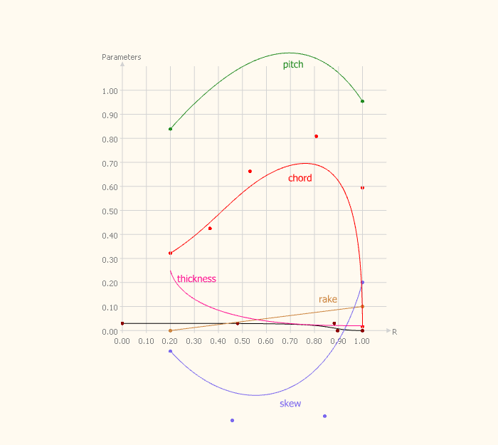

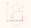
Propeller Geometry curves- non-dimensional Pitch, Skew, Camber etc.
in General Modeling
Posted · Report reply
Hi Suraj,
the default option for the pitch is the pitch to diameter ratio. So you have y-values around 1 and then you scale the function values by 2, because you define everything for a radius of 1.
For the exact definition you can also refer to the documentation:
best regards
Carsten