


Mr. Heinrich von Zadow
-
Content Count
223 -
Joined
-
Last visited
-
Days Won
12
Posts posted by Mr. Heinrich von Zadow
-
-
Hi Maria,
yes. You can couple any tool that can be run in batch mode via the Software Connector. There are a few tutorials on connections that should give you a good idea on how to start.
Cheers,
Heinrich
-
Hi Chien,
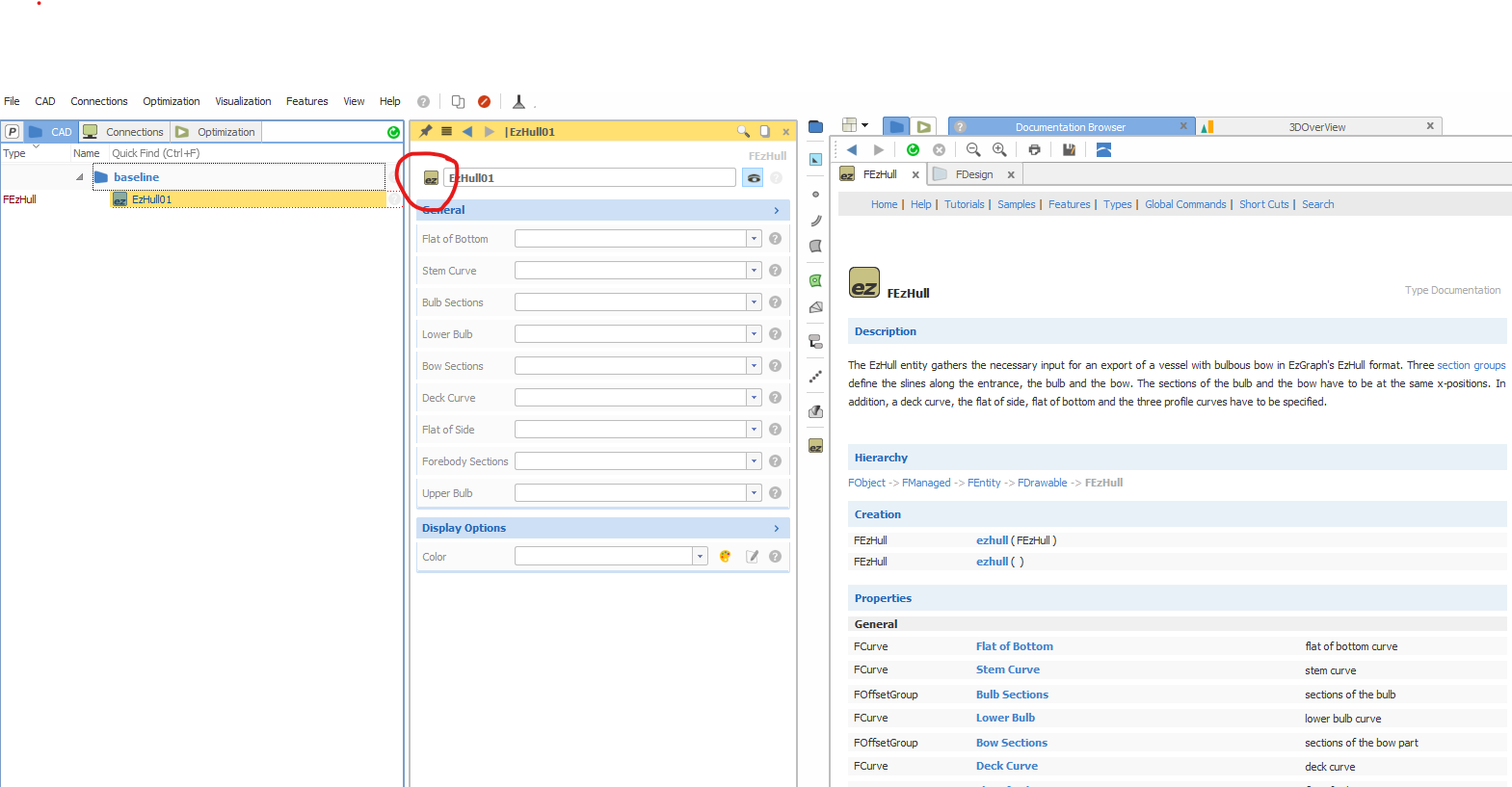
maybe you can start by taking a look at the type documentation. You find it by clicking the icon next to any objects name (see screenshot).

Cheers,
Heinrich
-
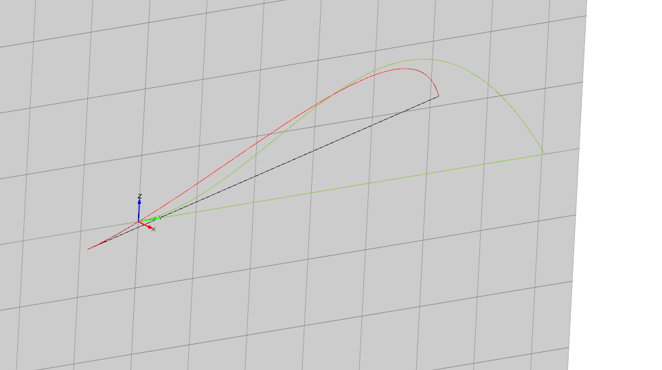
One small note on this: I used three points on the input curve (start, half length and end) to determine the plane in which the curve is positioned. If those points happen to be aligned in your case you will have to adjust the second point to something that works robust for your case...
-
Hi Simone (and Bodo),
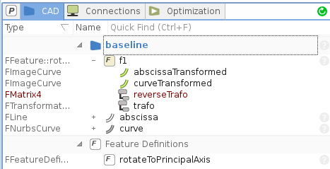
I have wrapped everything into a small Feature for you...
Inputs are:
1. the curve you want to investigate
2. the principal plane you want to have it in
3. a line (in the same plane as your initial curve), i.e. simply connecting start and end, which will be aligned with the principal axis' abscissa
Outputs are the transformed curves, as well as the transformation and a reverse transformation in case you want to use this definition for other use cases...

Attached are both, the definition and a small testcase.
Cheers,
Heinrich
-
Hi Anup,
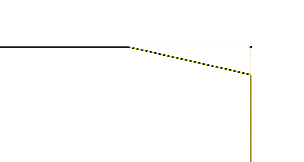
don't worry about the 'tapered' corners - thats just the resolution of the curve rendering. The underlying curve should have a perfect sharp edge.
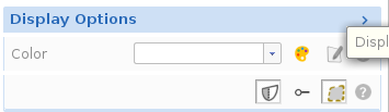
To verify, you can take a look at the curves control polygon by toggling the respective button under the curves display options:


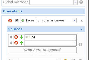
To get the Brep, you will have to activate the 'faces from planar curves' operation you have already created (see the small checkbox):

Best regards,
Heinrich
-
Hi Amin,
If you want to do hydrostatics based on sections for a trimaran (the same applies to cat hulls) you will need sections that run through all hulls of the ship. If you want to consider heeling make sure to use a symmetric (port+starboard side) geometry.
If you attach your project I could take a look at what is missing...
Cheers,
Heinrich
-
Hi MooSung,
all right, that is the latest you can currently have.
Could you please give a few more information on what is shown on the screenshots you have attached?
I can't see anything wrong with your script. Maybe, try without -x after shebang and make sure you have all paths correct both, in the fsc and the sh file.
Have you checked the CAESES Documentation browser under tutorials/learn more/batch mode?
Cheers,
Heinrich
-
Dear Anup,
now Jörg was a bit faster, I will post my reply, anyways...
If you really need a surface, I suggest you use a ruled surface. In this case you will have to ensure that the parametrization of both curves is somewhat similar, e.g. they both start at the bottom and run counter-clock-wise at the same 'speed'.
A bit more straight forward would be if you use a brep and create the rectangular surface. From there you could project and trim the circle...
I prepared a small example for you that contains both options.
Best regards,
Heinrich
-
Hi MooSung,
can you please confirm you are using the latest Version of CAESES?
Best regards,
Heinrich
-
Dear Kim,
try simply recreating your shell script under Linux or refer to this post for a more detailed explanation:
https://askubuntu.com/questions/304999/not-able-to-execute-a-sh-file-bin-bashm-bad-interpreter
Also the attached script should work for you...
Best regards,
Heinrich
-
Dear Chris,
that is good to hear, glad I could help!
I think it would be very nice if you could come up with a 'clean' final version of the project so that other user searching the Forum can profit as well.
Cheers,
Heinrich
-
Hi Chris,
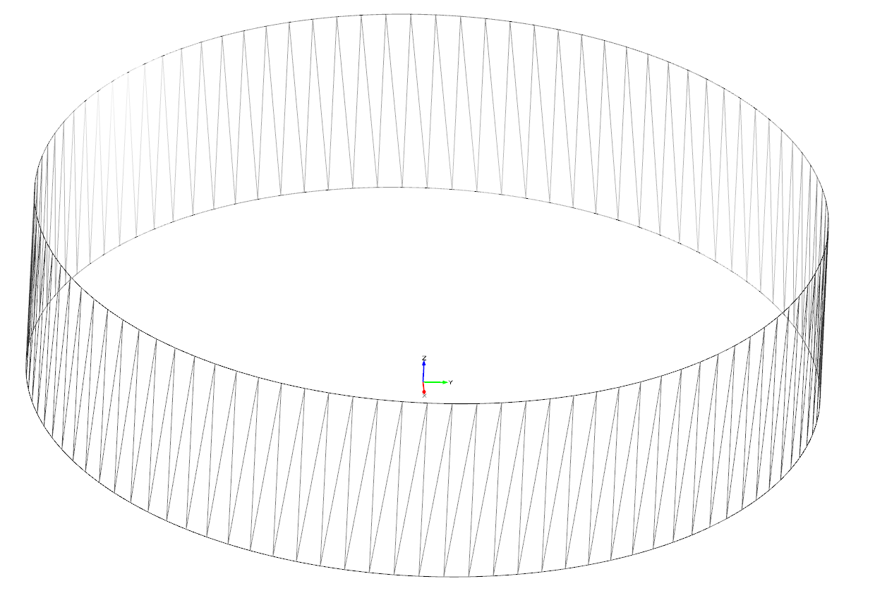
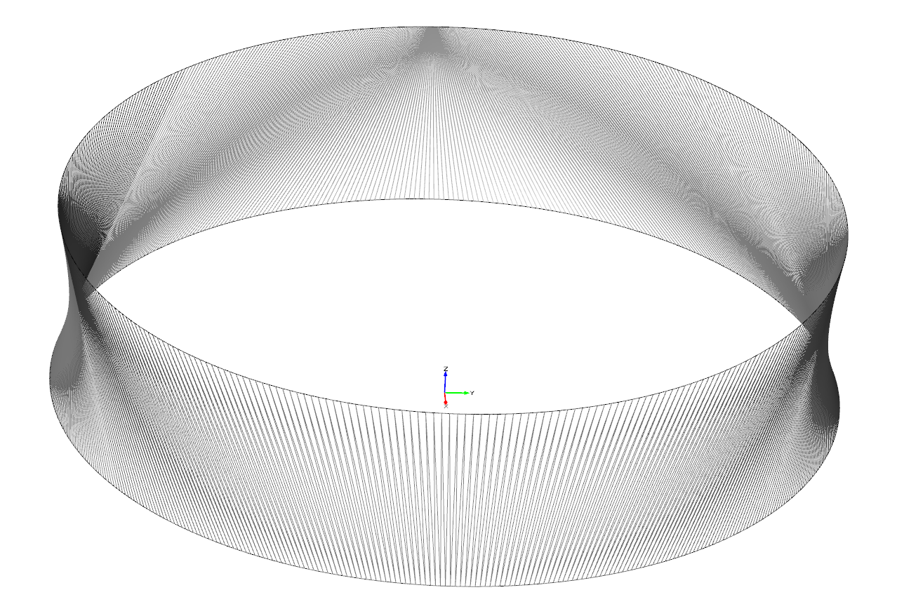
1. The 'role' of unit speed is nothing more than parameterizing the curve such that the internal parameter t[0,1] runs with equal 'speed' per curve length. Since ruled surfaces create straight rulings between equi-parametric curve positions the parameterization allows you to massively influence the shape of the resulting suface - see example of two circles and the ruled surface in between for different parameterizations.

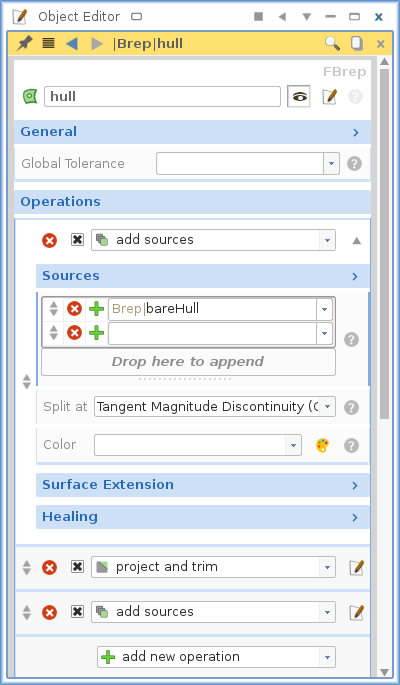
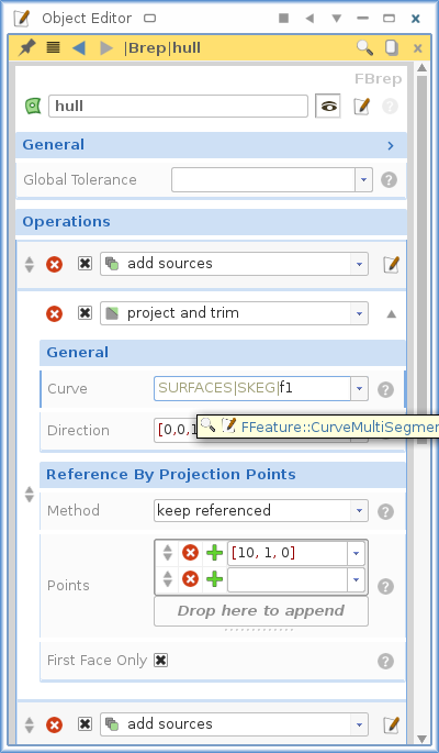
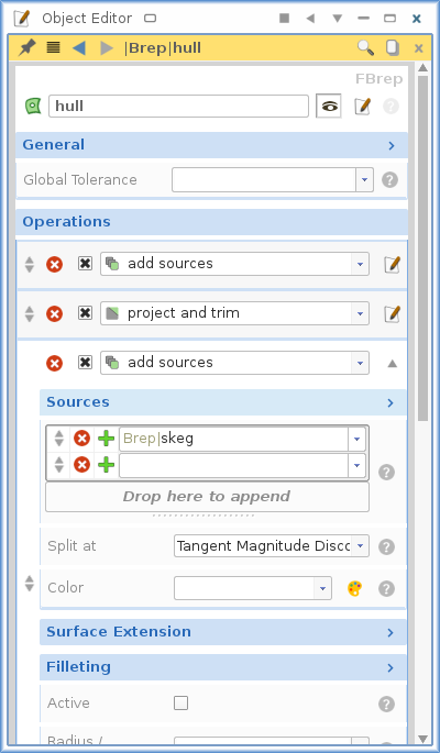
2. Check the object editor of the Brep. The 3 steps I used are:
1. add sources (bare hull)

2. project and trim (skeg contour)

3. boolean sum (skeg)

3. In the file you attached, the 'number of interpolated points in surface direction' for the meta surface main was set back to 15. I checked with 4.4.1 and it works for me.
Cheers,
Heinrich
-
Dear Chris,
1. In that case, it is the parametrization of the curve that is important. For ruled surfaces it is always a good idea to have at least a somewhat similar parameter distribution on both rails.
2. That is because your Brep is not trimmed either.
3. It works for me - which CAESES version do you use?
I put the Brep together so you can understand better how this is supposed to work in CAESES and I also created a set of sections as I understand this is what you want to export.

P.S There are filters on the bottom of the 3D view to turn on/of the sections / offsets / surfaces etc... so you don't have to turn off the section visualization manually
Best regards,
Heinrich
-
Dear Priyanka,
I can not see any attachments, but since this thread is more about fully parametric modelling while you are interested in a partial parametric approach - why don't you just open another thread to keep things a bit more organized. Feel free to sent me a PM when you have done so and I will take a closer look.
@Chris:
1. It is not about the image curves - they are just used to allow trimming.
2. Try increasing the number of sections of the main meta surface. Keep in mind, that you will have to ensure a horizontal tangent at the end of this chine curve other wise you will loose continuity towards the bow region.
3. You will most likely need something like the 'subsurface from surface curve' (in surfaces / sub surface / more / ...)
Cheers,
Heinrich
-
Hi Chris,
1: I checked your project (with the rail 'ProfileImage') and I can't see any problems at all.
Without using a rail it is normal to have a slight oscillation in the surface. This can be reduced by increasing the number of interpolated sections ('Interpolated points in surface direction' input for the meta surface). If you add a rail you will have no oscillations at all on the surface edge.
Zooming in is not always the best way to judge things due to the limited render resolution. (Increasing the resolution in the display options of curves and surfaces does NOT change the geometry but only the rendering...)
About the skeg: the parametrization of the surfaces was not ideal. For ruled surfaces it is always helpful, if the rulings are not warped too much... I replaced the input curves by imagecurves for which I set the parametrization to 'unit speed' (you can do that in the object editor in the 'general' options...)
From here I suggest (instead of creating subsurfaces etc... ) you continue with Brep modelling as this makes it very easy to combine skeg and hull, as well as close the hull and possibly create a computational domain for you CFD at a later stage...
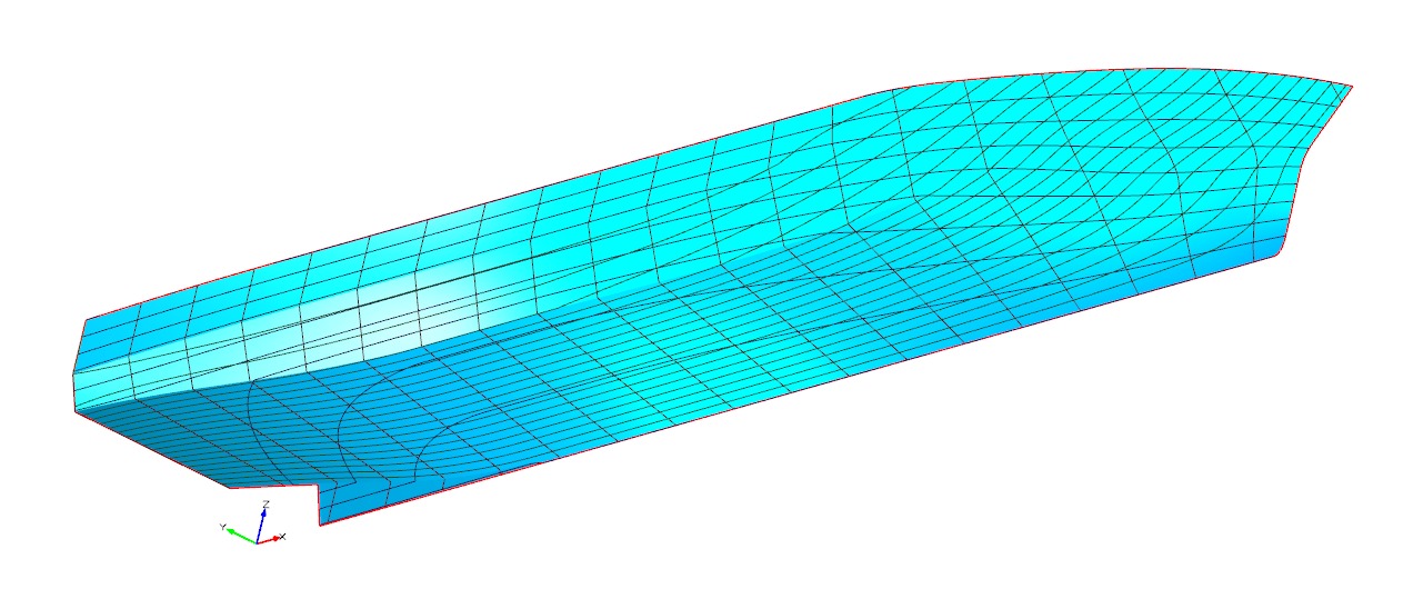
2. See my answer to question 1. There is no hole - you can also visually check the surface by when looking at the Brep 'hull'
Hope you are making good progress. Cheers,
Heinrich
-
Hi Chris,
yes, that can in fact be the case. Just add a rail to the meta surface to make it exactly match the cpc.
Regarding the pole warning in PROSTEGO/s1, that refers to the curve c6. I changed the input curve 'imagecurve1curve' (it now gets the actual surface edge as input) to fix this...
You now have another pole warning tracing back to your imported deck contour --> you should probably create a nice reparametrization of this...
Now on to priyankas question. Regarding the modelling, you can choose to follow the way Chris has chosen and build up a fully parametric model based on the geometry you have imported. The alternative would be a partial parametric hull where you can choose from a wide variety of free form deformation and shift techniques inside CAESES. Of course, also a combination of both approaches is possible.
The tricky issue - keeping the displacement constant while changing the geometry - can easily be achieved through a nested optimization. You can read how that works and download an example from this post:
https://www.caeses.com/forum/index.php?/topic/734-constant-volume-kept-during-dakota-optimization/
If you choose a Lackenby shift you can directly adjust the XCB (longitudinal center of buoyancy) and displacement of your vessel - take a look at this video:
https://www.caeses.com/blog/2016/video-adjusting-displacement-and-lcb-in-5-minutes/
Hope this helps.
Best regards to both of you,
Heinrich
-
Hi Chris,
this is really just a display thing and not related to the accuracy of the underlying nurbs. If you create your section group with the Brep as an input, you should have a distinct edge at the chines...
Best regards,
Heinrich
-
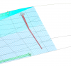
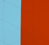
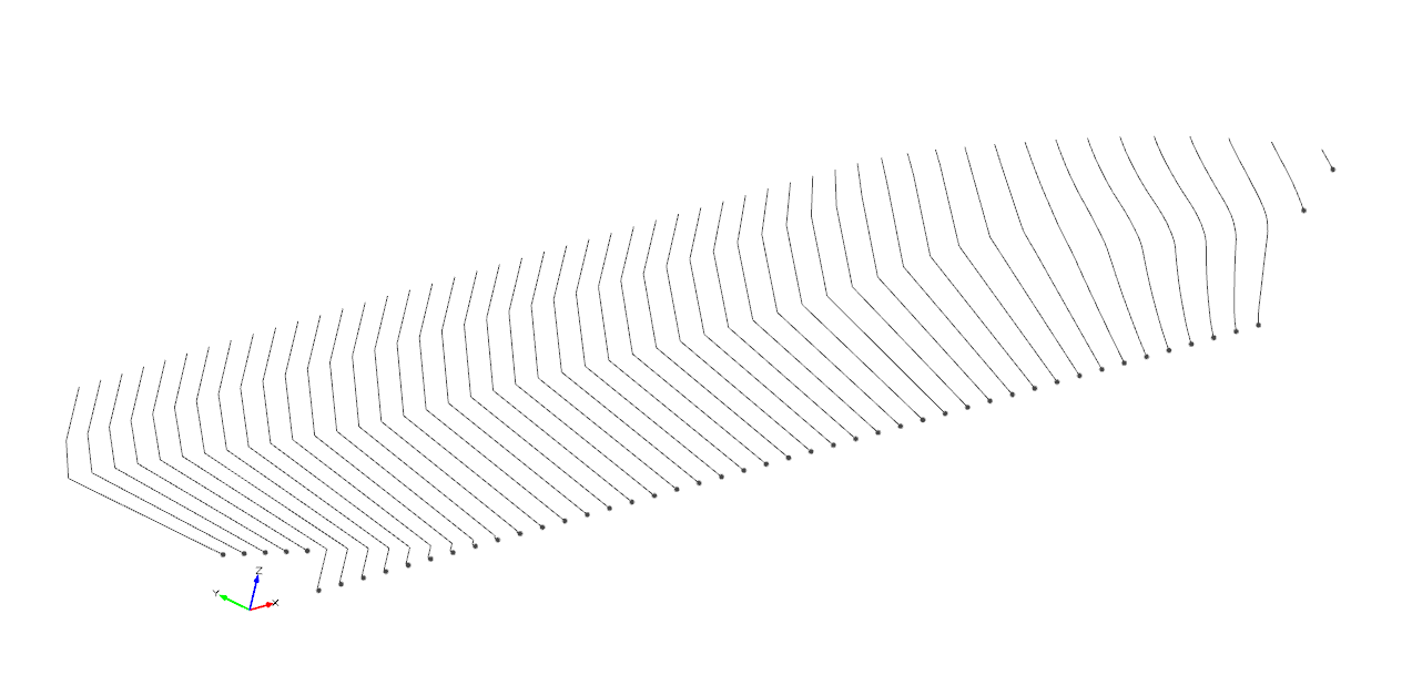
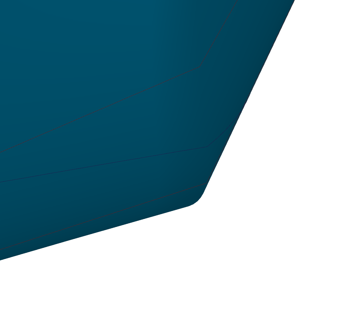
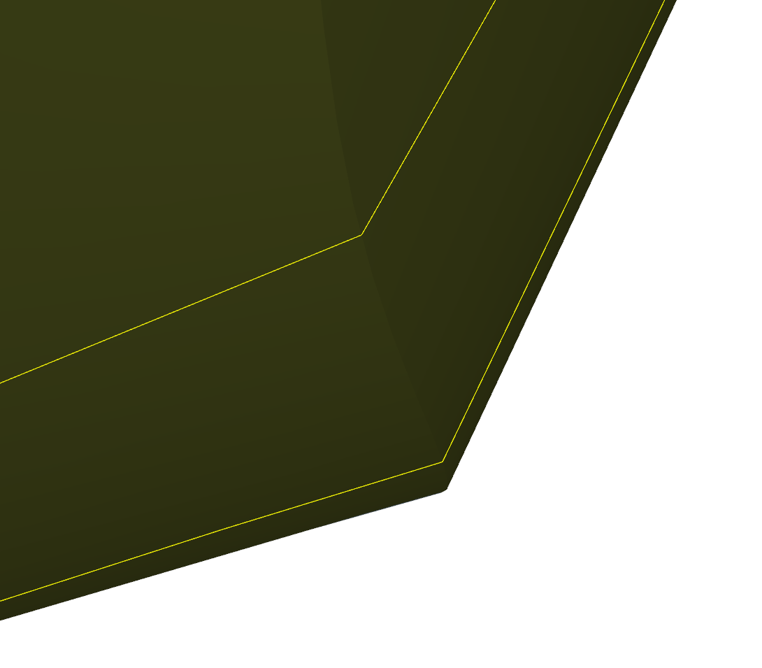
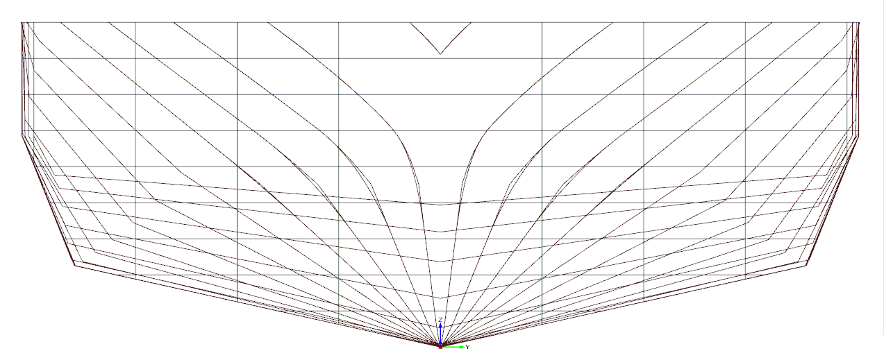
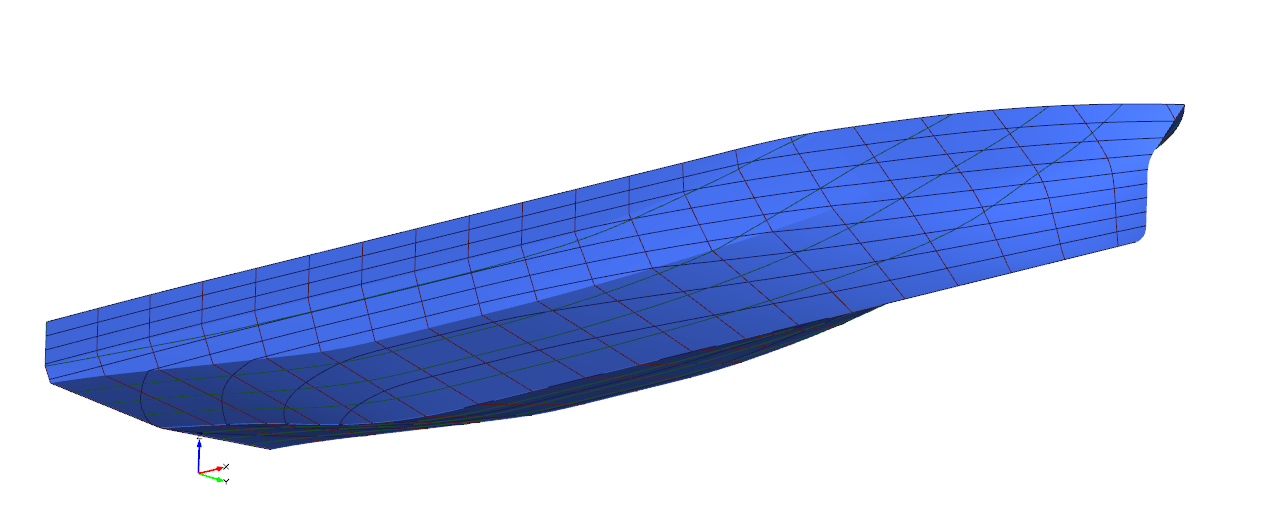
Hi Chris,
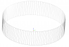
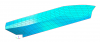
when you look at the surfaces in 3D you can see some kind of rounding at the chines as shown in this picture:

However, this rounding comes only from the rendering resolution (the edge gets sharper if you increase the resolution in the display options of the surface). The underlying Nurbs representation exactly meets the specified edge with a distinct sharp corner, as you can see when looking at the brep of the hull:

So there is nothing to be fixed here...
Cheers,
Heinrich
-
Hi Chris,
Usually you should not have to go through any fairing procedure. Once you have set up your parametric model it should give a fair hull surfaces for any geometry variation. Often times, this means that you will have to create a few designs automatically as a robustness check or manually play around with the design variables to find a parameterization that does not lead to unwanted shapes.
For the main part of the hull, your only means of changing the shape is of course to adjust the underlying curves. For the bow region you can play around with the feature I created for you - this was really just meant as a starting point...
Of course there are various ways to investigate smoothness in CAESES. You can find them in the display options of the curves and surfaces e.g. display normals, map curvature (gaussian / mean), isophotes, etc...
Best regards,
Heinrich
-
Dear Mr. Xuxiang,
I will answer your message here to keep this thread alive...
From what I understand you are not using CAESES for you geometry generation so far. Maybe you are enrolled in a university currently? This way you could get a free trial license and take a closer look at CAESES and how to use it's optimization tools in the process of geometry generation.
The basic idea is as follows:
Say you have a set of design variables which you want to vary while keeping the volume constant. You then choose one of the variables to not be changed freely, but to be adjusted always such, that your volume constraint is matched.
The next step would then be to connect CAESES and OpenFOAM to run an optimization to minimize drag/lift ratio. Any variant generated during this optimization will automatically match your specified displacement.
Note, that there is actually a tutorial on the connection with OpenFOAM that comes with CAESES so this task should be pretty straight forward...
Best regards,
Heinrich
-
-
Hi Chris,
first things first: The parameter runs from 0 to 2/3 as the main surface of your hull is a meta surface that has a poly curve as section definition. This poly curve is made up of 3 straight parts, each straight part makes up 1/3 of the parameter range... At the junction (at 31.8 m - where we want to connect the bow surface) the top-most surface just disappears so you are left with a u-domain of only 0 to 2/3. The remaining 2/3 to 1 range represents the position of the corner... (you can get a good visual impression by clicking the wireframe filter and looking at the surface tesselation)
Of course, you could also run from a constant zPos at the surface edge to the same height at the stem. This way you will have to use the .fv() or .ft() command twice. In my case you can use .getPos() on the surface edge and .fv() at the stem. Since .ft() and .fv() are a bit more costly I made it this way, but the resulting surfaces should not be any different.
You are right about the missing part of the stem (I just made trimmed that 'quick and dirty' ) - feel free to correct it to the exact value.
I fixed your meta surface by:
a. correctiong the uPos curve (it has to start at [0,0,0] and end at [0,2/3,2/3] ) This always has to match the specified plane in the curve engine.
b setting the base position at the end of your meta surface to 2/3
and c. by setting two rails to exactly meet the stem profile and get a perfect junction towards the main surface
Now I started playing around. I created a curve, again in the y,z plane that represents the fullness (using the area argument of the FSpline) along the parameter u. This way you can set a certain fullness at the waterline and also at the deck... and have a smooth transition in between. I did the same thing for the entry angle of the waterlines...
From what I can see those small curves you get close to the origin are the domain curves of the projection (you can simply hide them if not needed by untoggeling the 'Show Domain Curves' field in the object editor of the projection curve).
I will send the remaining attachements in the next post...
Cheers,
Heinrich
-
Hi Chris,
I will answer here so others can make use of this thread in future as well.
Regarding 1: Like I already mentioned you can not simply attach a meta surface with a rounded section shape to the main surface with the knuckle. You will not get a smooth transition here and as soon as you start changing any parameters the small gap that is already visible right now might get bigger...
2. Can you please point me to the .fdb file or re-upload it here? I can not locate it searching for Supply_Vessel_Exemple in the Forum.
Once again, I really recommend you to work through the tutorials! Get familiar with the concept of the meta surface - it will allow you to create any free form surface you can imagine. In case of the bow, like I said, I would probably create a feature that gives the kind of waterlines I have in mind and then create a meta surface from this feature definition.
The most difficult part is probably to 'extract' the tangent information from the adjacent surface, so I went ahead and did that for you. In the attached project you can use the slider to change the design variable vPos and see how the section moves up and down. From there you can start to modify the feature definition (e.g. change the fullness of the Curve, set an entrance angle for the waterline, etc.) For each parameter you introduce you can then decide whether you want to have this value fixed over the entire surface or if you want to have a smooth distribution instead where you supply a curve instead of a fixed value to the curve engine...
edit: and don't get confused - I mixed things up. Obviously the designVariable should be named uPos...
Hope this helps! Cheers,
Heinrich
-
Hi Chris,
alright, here we go:
A: of course, the coons patches have an angle at the waterline since there is no tangent inforamtion passed from one surface to the other. A simple solution to smooth this area out would be to trim both surfaces and add a fillet surface in between. As those pictures show:


B: You had the xPos curve wrong. This should be a straight line running at 45° - it simply means, that the curve engine looks up the z-value a every x-position of this curve and then uses this z-value as x-Position for the current section...
In this case, there will be a discontinuity between the main hull and the bow, since the main hull has a sharp knuckle at x=31,8 m so you can't just connect a rounded section... When using the CoonsPatches, you can avoid the problem by not making the fillet to wide. You could even think about widening it towards the stem if need be...
The resulting hull from trimming and filleting the CoonsPatches looks good to me so I will leave 1 and 2 for you to figure out by yourself if you are still interested ;)

Cheers,
Heinrich


Using Ezhull in Caeses
in General Modeling
Posted · Report reply
Hi Chien,
the way I understand it, the FEzHull is more like some sort of container to gather relevant geometry data and export to EzGraph. You could probably just start with an imported geometry, e.g. KCS.
Cheers,
Heinrich