


Mr. Heinrich von Zadow
-
Content Count
199 -
Joined
-
Last visited
-
Days Won
9
Posts posted by Mr. Heinrich von Zadow
-
-
Dear Solehah,
we are awaiting your response on the Ticket you opened.
Cheers,
Heinrich -
Dear Aina,
I am happy to take a look but would need the project file and/or the exported IGES you mentioned.
From the screenshot it looks as if your geometry is not fully watertight -- that might be a starting point for investigation. Furthermore, the displacement calculation is based on the triangulation settings -- the coarser, the larger the error. But typically the deviations here are not as large as you experienced them.
Finally, if you calculate displacement at a certain draft, heel and trim, the order of transformations and the origin you choose may drastically impact the result. I don't know about Numeca, but in CAESES we transform in the order heel, trim, draft and use [0,0,0] as default origin. You can also specify otherwise by using the .getDisplacementOrigin() command.
Kind regards,
Heinrich -
Dear Aina,
typically the absolute path to your FineMarine installation followed by a space (" ") and the path to the *.sim file should work. Just check it manually in a terminal window.
Best regards,
Heinrich -
Dear Lixing,
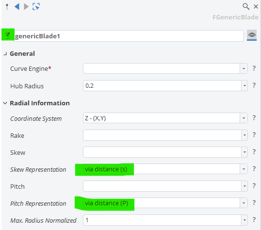
The questions you are asking are explained in detail in the type documentation -- just click the icon left of the name of your blade. Also note, that you can choose between different options for the representation of skew and pitch:
Best regards,
Heinrich -
Dear Solehah,
thanks for preparing the file. Here's a few comments:
1. I can see that you have a number of individual Trimesh Parts. None of them has a color. Typically what you would want is a watertight geometry of the domain with the individual patches colored (the color names will be exported as the names of your boundary conditions). I recommend you color the individual parts and join them together in a single Trimesh like this:

2. Make sure to reference to the exported geometry in your sim scripts (maybe I just overlookerd it, but I could not find the file names you used for the exports in there. Lines 8-9 in your existingShip.iec file don't look good.
3. Your Connector runs the local Application FineMarine without any additional arguments. I imagine that you either need to specify the sim file as argument or, alternatively come up with a batch file that takes care of running things.
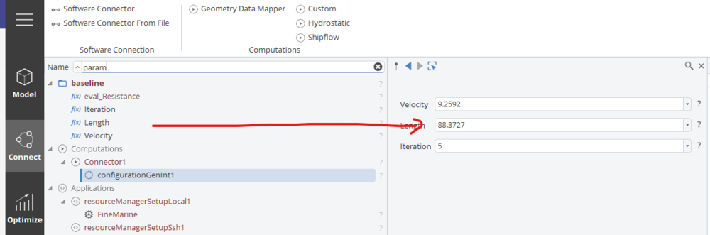
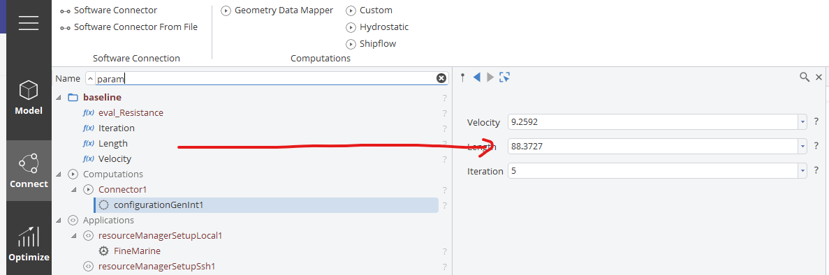
4. If you want to have parameters for certain inputs you will need to assign them to your configuration (i.e. drag & drop):
I'll leave it at that for now. If you still run into trouble, I highly recommend you follow through a few tutorials on the subject. The procedure is always very similar.
Best regards,
Heinrich -
Dear Solehah,
since this is a forum, I'd would like to ask if you can provide a (possibly simplified) version of your project that you are willing to share with other users? This way we can create a knowledgebase that allows the entire CAESES community to benefit.
Best regards,
Heinrich -
Dear Latoya,
thanks a lot for the flowers!
Cheers,
Heinrich -
Dear Solehah,
you can refer to the provided tutorials on software connection. The basic principles are always very similar. After you have tested things manually you should know what geometry is needed and in which format. My guess is a colored STL of half the domain with the ship substracted from the domain at roughly the right floating condition. Extra care needs to be take to account for triangular patches as I mentioned in my first post.
If you want CAESES to read in pictures generated from Numeca (or any other tool in your chain), PNG works fine.
You will want to run Numeca in batch mode to avoid the GUI showing up.
Best regards,
Heinrich -
Dear Solehah,
at least I can't see anything that's obviously wrong from the screen shots. If you have an STL I would recommend that you start by setting everything up in Numeca (completely independent from CAESES). Once things are meshing and running/converging the way you want them to, you can go back to testing the CAESES integration. This way it's easier to know where to trouble shoot...
Cheers,
Heinrich -
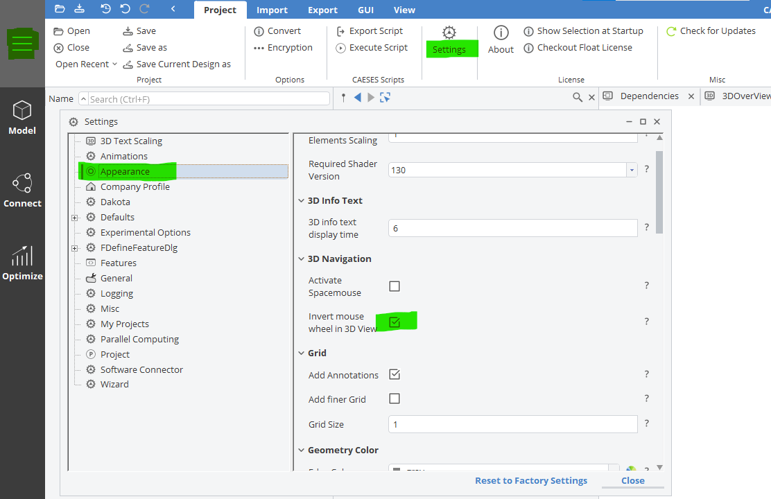
Hi Gustaf,
you can adjust the zoom direction in menu > setting > appearance:

Best regards
Heinrich -
Dear Solehah,
A Mesh Engine will only allow you to generate surfaces meshes as you would need them for potential flow simulations i.e. for wave making resistance. To run ranse CFD in Fine/Marine you would need to use their HEXPRESS grid generator and supply the flow domain as an STL.
Best regards
Heinrich -
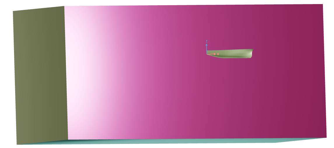
Dear Solehah,
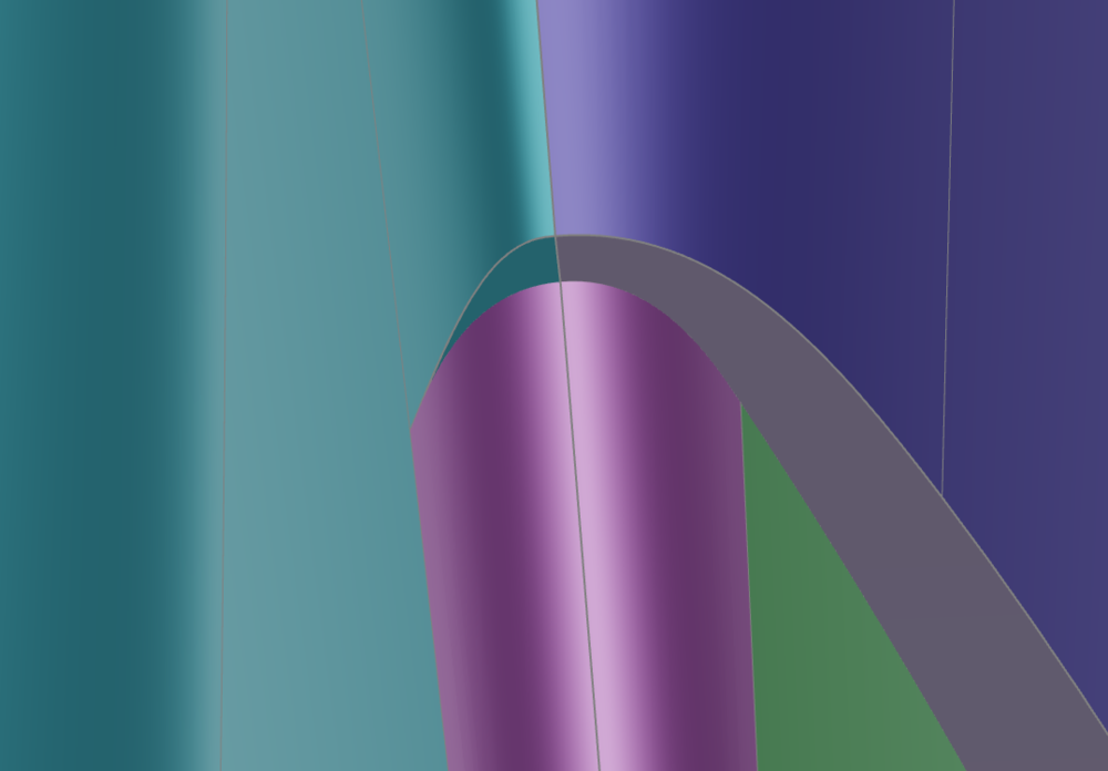
with HEXPRESS Numeca Fine/Marine offers a powerful meshing tool which is well matched to their requirements for CFD. Afaik the input file for Numeca (output in CAESES) would be a domain either half or symmetric in colored STL. The only pitfall I am aware of is, that HEXPRESS does not like triangular patches. Hence, if you have them, you would need to join them with a neighboring patch so that the cells can "float" across the patch boundaries (see below image where I colored the small triangular patch in turquoise instead of grey to avoid the described singularity).
As an Input to CAESES any text file containing the information of interest (resistance?) should do just fine.
Cheers
Heinrich -
Dear Aina,
it seems that you have not selected any points for the 3 transformations that you have prepared. I attached a small demo of how that's done as well as the modified project.
Best regards
Heinrich -
Hi Osman,
I'd start by checking the directory from TSearch Nr. 15 on your hard drive. Are the respective directories in there and do they contain any screenshots?
Best regards
Heinrich -
Dear Aina,
have you checked my suggestions from above? If this does not help, feel free to attach the project here and I am happy to take a quick look.
Best regards
Heinrich -
Dear Rizuan,
yes, indeed -- an image surface will always be an image of only one individual surface. You can wrap multiple surfaces into a surface group. An image surface group would then allow you to transform all of them at once. Alternatively, you can use a BRep which also accepts transformations and can have multiple sources.
Best regards,
Heinrich -
Hi Osman,
you can use a parameters to define the bounds and design variables to scale in-between. See attached example.
Cheers,
Heinrich -
Hi Rizuan,
An image surface only accepts surfaces as input, no BReps.
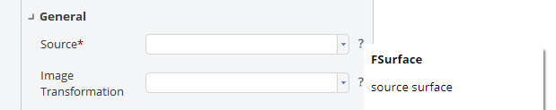
You can have images of individual BRep patches (or their underlying, untrimmed NURBS surfaces, to be more precise) by setting "brep1.getSurfaces(0)" as a source. Obviously, 0 can be replaced by any other surface ID... Here is an example:
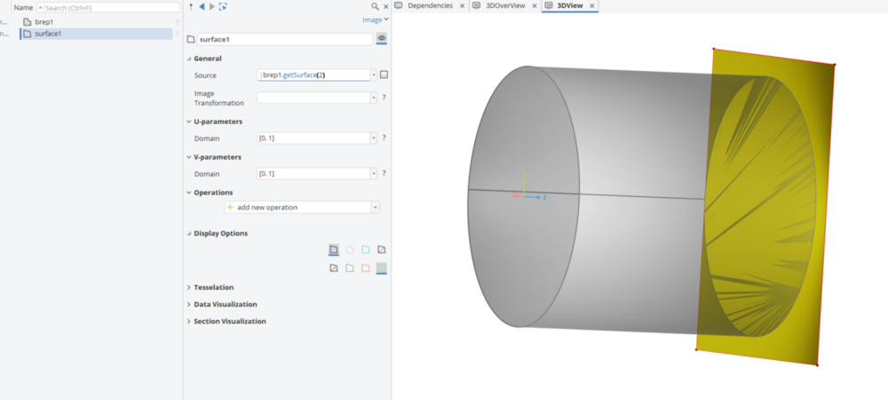
Note, that the underlying surface of the circular patch is actually rectangular (That's what BReps -- "boundary representation" -- are there for, after all).
Hope this sheds some light onto the topic. Why is it, that you wanted to create an image, anyway? Maybe there is a different way to get what you are after.
Best regards
Heinrich -
Dear Rizuan,
Offsets can be found in the maritime tab:

CAESES maritime functionality requires a separate license package but is included in the non-commercial edition as well.
Best regards,
Heinrich -
Hi Carlos,
we don't ship anything readily with CAESES but maybe you can start off from an imported geometry -- something like a standard test case (KVLCC2 or similar) and then apply partially parametric modelling techniques such as Free From Deformations or BRep Morphing to vary the shape.
Best regards,
Heinrich -
Dear Kala,
I recommend you take a look a the design velocities to understand how a certain design variable impacts the shape.
On our channel you can find a video that explains the concept:
https://watch.caeses.com/w/tvEDgJu9ThsVZPPDUTCiJJCheers,
Heinrich -
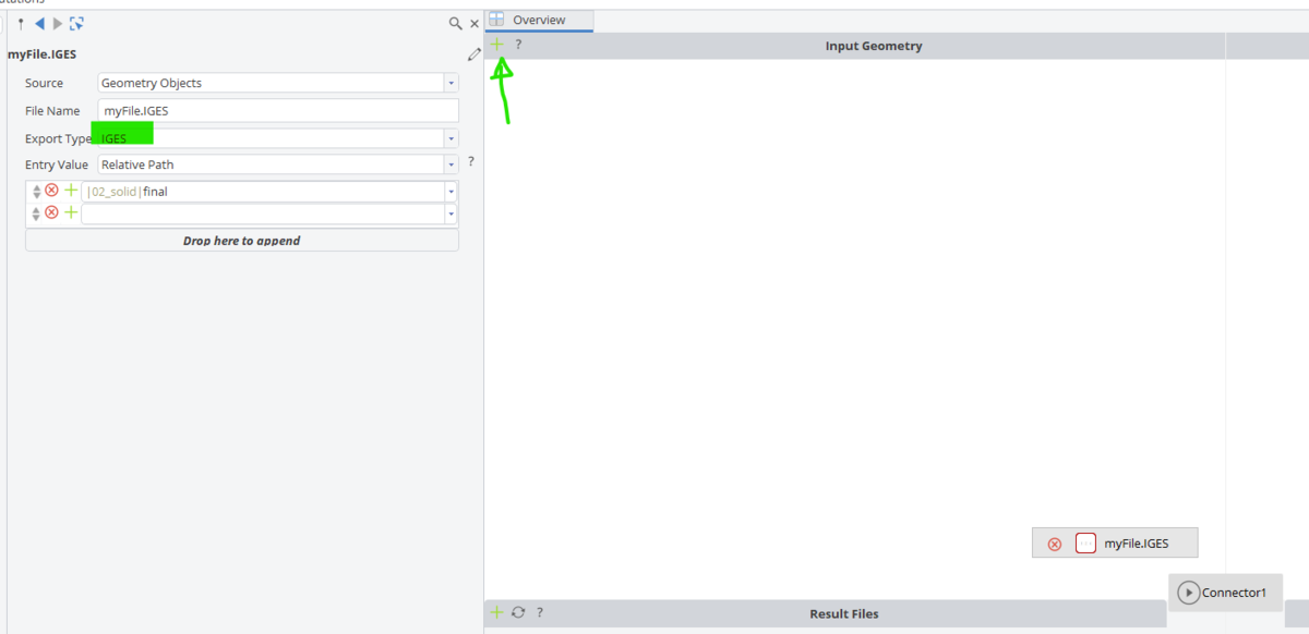
Hi Martyn,
just add the geometry you want to export as input geometry to your connector like this:
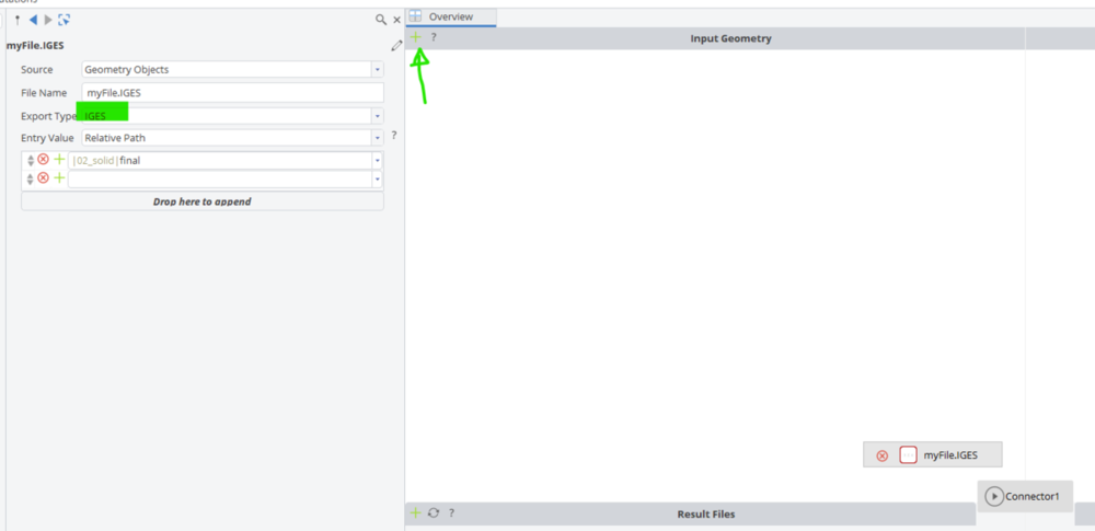
Cheers,
Heinrich -
Hi Mansur,
yes, you can simply drag and drop designs into the table from the object tree on the left (as you can do with parameters and design variables as well). Also, since you screen shot gave it away -- I highly recommend you update to the latest release 5.0.1 😉
Cheers,
Heinrich -
Hi Rizuan,
very good. FINE and CAESES are well known combination so hopefully it will be 'smooth sailing'...
Cheers,
Heinrich-
 1
1
-


How to find rake of a B series propeller
in General Modeling
Posted · Report reply
Dear Althaf,
in the documentation for the FGenericBlade you should find all the details, including the following figure:
Best regards,
Heinrich