


Mr. Heinrich von Zadow
-
Content Count
223 -
Joined
-
Last visited
-
Days Won
12
Posts posted by Mr. Heinrich von Zadow
-
-
Hi Yukai,
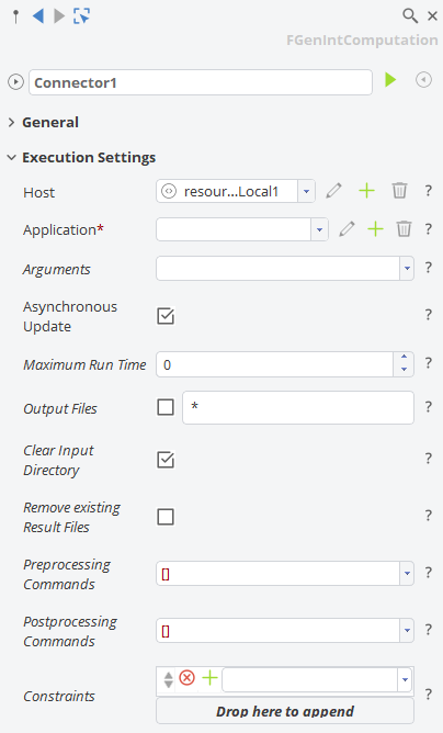
you can set up an inequality constraint and use it in your Software Connector under Execution Settings for that.
Cheers,
Heinrich -
Hi Yasi,
in your screenshots I can see the 3DView and 3DWindow:
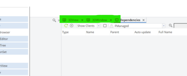
If you select them and don't see what you are looking for, check that the objects are visible in the object tree, as well as the filters of the individual views. I recommend to familiarize with the GUI by going through some of the basic tutorials. There is one specifically about object visibility as well in the GUI section...
Cheers,
Heinrich -
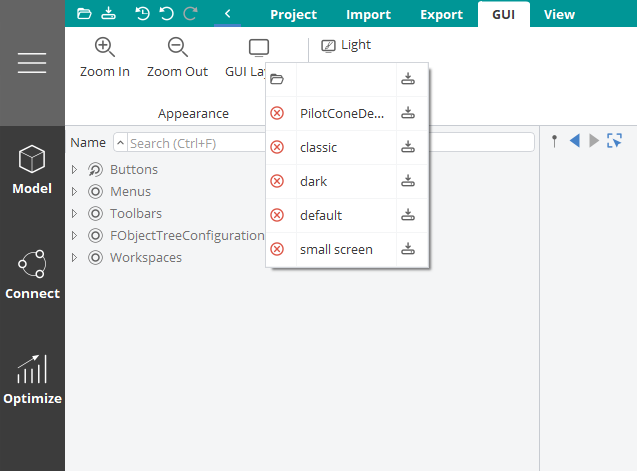
Hi there,
you can reset the GUI layout to default here:
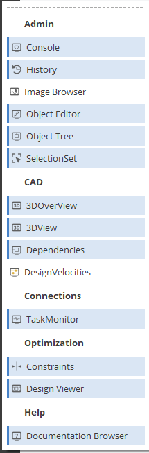
also, if you right-click the dark ribbon on the left you can find windows that are currently not shown:
Cheers,
Heinrich -
Hi CJ,
you can set constraints to your computation. If violated, the computation will not be executed. Of course, this only works if the constraint can actually be evaluated before the CFD ran.
Cheers,
Heinrich -
Hi CJ,
this question is a bit unusual. Maybe if you explain why you want only specific variants out of a Sobol I can try and come up with a better way to approach your problem.
Technically though: you can select specific variants, export them as csv from the table and then use a Design Assembler (which allows to import said csv again).
Cheers,
Heinrich -
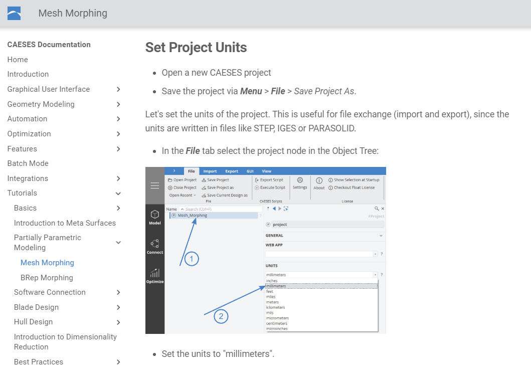
Hi CJ,
if you check the documentation for "units" you should find this:

Cheers,
Heinrich-
 1
1
-
-
Hi Furkan,
if you have set the constraints in the Design Engine, the algorithm predicts an optimum within the feasible domain. However, predicting constraints (which is technically the same as predicting objectives) comees with uncertainty and hence, sometimes none of the predicted optimal designs is actually feasible. What might help is, to set a narrower margin in the Design Engine and try again.
Cheers,
Heinrich -
Hi Furkan,
If you set up a "Response Surface Optimization" and choose to "use result pool", a surroate will be created (if your pool is large enough, otherwise samples will be added first). An optimization on that surrogate is performed automatically in the background (a Genetic Algorithm is used here) and the optimal candidate (or multiple if you choose so for a multi-objective problem) is returned.
The design you see created in CAESES is therefore either an additional sample or already the potential optimum. Check the dakota.out file in your design directory to see the details. Also, the finaldata file will show you the predicted performance of the optimum...
If you keep this Algorithm running, the actual (CFD) result(s) of the optimum-candidate(s) will be added to the pool for the next iteration and the process repeats.
Cheers,
Heinrich-
1
-
-
You can simply drag&drop it from the file explorer.
-
Hi Yukai,
yes, both will start a new run counting the designs from desing0000 and onwards. It's just that in case 1: the designs (in terms of values of the design variables) that are created are the exact same you would have seen if your initial Sobol ran through. In case 2 things will start from the beginning again, but the designs you have already run a CFD for will be linked instead of re-run.
You can just grab an easy and fast example (e.g. the Jumper Sample) and play around a little to get familiar.
Cheers,
Heinrich -
Hi Sisi,
just a quick comment on that: the propeller object (type FPropeller in CAESES) does not support an actual tip. It is a type ment specifically to work with the PFF format (and be exported as such). If you want a closed, solid geometry including a tip checking out the sample mentioned by Andreas is the right way.
Cheers,
Heinrich -
Hi Yukai,
There are 2 options in your case:
1. Set the Sequence Start Index of the Sobol to 10 (or wherever it stopped the first time) so that it does not start from the beginning when you run it the second time.
2. Select the result pool from the first run when starting the second one. This way, the results will be linked and the CFD is not re-run.
Cheers,
Heinrich -
Please see my two posts above...
-
Hi Ramond,
the project shown in the first post cannot be shared publicly, unfortunately. I am happy to provide some guidance and assistance if one of you wants to take on a similar task.
Cheers,
Heinrich -
Hi Joshua,
if you want to change the positioning, number, shape and size of the holes shown in your screenshot I would indeed recommend, to re-model this part from scratch instead of morphing/deforming/shifting it...
I guess I'd start with a bare tube (i.e. a circle which you use in a BRep and extrude it) and then a parametric (in number, positioning, shape, size etc.) description for the holes (which I would create via a boolean operation). I just created a very simple example for you to explain the basic process, hope this helps to get you started.
Cheers,
Heinrich
-
Hi there,
unfortunately the project you are referring to cannot be shared publicly. However, if you have a fixed blade geometry and want to investigate a variation of the cooling channels, a model can probably be set up quite easily. If you have something to work with, feel free to share it here and I'll take a look.
Cheers,
Heinrich -
Hi Susan,
I don't have any experience with Sesam, but I'll assume it depends on (any number of) input files and input geometry and after running the tool in batch mode there will be (again, any number of) results files. If that is the case, the connection through the Software Connector should be basically the same, as any other. I recommend you start by looking at the respective Tutorials (e.g. Jumper, StarCCM+).
Cheers,
Heinrich -
Hi CJ,
sounds like CAESES is waiting for StarCCM+ to return the results files. You can either follow the output in the CAESES Task Monitor, or navigate to the current design directory (if you manually execute the connector this would be .../manual_results/baseline/Runner) and see what's happening in there.
Basically, the directory should include everything you need to run the external computation. Just give it a try and make sure it is working (by manually calling the script or StarCCM+ with the corresponding macro inside that directory). Once you have confirmed the computation runs independent of CAESES, you can come back and trouble shoot the connection set-up in CAESES.
Cheers,
Heinrich -
Hi Ail,
there should be a generic integration of external tools into heeds that is based on running the external tool in batch mode via a script. CAESES wise things look good -- by changing the values in your fsc file you willl be able to create different geometry variants. You will probably need to define an export, though. How to actually trigger thigs from HEEDS' side is probaby a question their support can help you with.
Btw: from the fsc file you attached, I take it that you still run a very old CAESES 4 installation -- I hihly recommend you to upgrade to the latest 5.x.
Cheers,
Heinrich -
Hi Susan,
If you use this method "smooth joint to stem" for the selected surface in your screen shot you will have to make sure the adjacent surface is defined such that it results in the same shape along the joint edge (possibly you will also want continuity accross the edge -- that would be another thing to keep in mind).
What about you trim the upper surface and extend the lower one all the way to the max height?
BTW: Which version of CAESES are you working with? Looks like a 4.x to me. I definitely recommend to update to the latest 5.2.4 -- there is years of development in between them.
Cheers,
Heinrich -
Hi Susan,
I'd recommedn to start with these: (they are part of any CAESES installation)

-
There is plenty of material. Have you had a look into the documentation?
-
That sounds like a good start. I'd start importing it and look into partially parametric modelling techniques. BRep morphing, Free Form Deformations, Delta Shifts all work well in different areas of hull design. If you have specific questions regarding particular shape variations, feel free to ask. A lot also depends on constraints and the objective of your optimization problem.
-
Hi Susan,
do you have something to start with (an existing CAD file, hull lines, etc.)?

Is it possible to Override the Maximum Degree of a B-Spline?
in Feature Programming
Posted · Report reply
Hi Tom,
technically for B-Spline and NURBS curves the degree can be up to number of points minus 1 (in CAESES it is indeed currently limited to 9 though). For G2 a degree of 3 is all that is needed. With 4 you can already get continuity in the change in curvature... Personally, I rarely go higher than 4 or 5.
Maybe the question is what you intend to do (you wrote that you want to get close to a given curve. However by increasing the degree you get the opposite: a degree of 1 still interpolates the control points. When increasing it, you get further and further away from it (and, as Andreas pointed out, trade local control for global a one).
If you want a good approximation you can try some of the following options:
1. A C-Spline (this is an approximation of a point cloud and you are free to choose the number of points and degree (still 9 is the limit)). Prone to oszillations.
2. A generic curve that reproduces another curve but has a limited number of control points. That is a nice trick but no tangent information at the ends are taken into account. But that can be fixed.
3. An approximation curve (there is an operation called approximate by tolerance). Relatively new type, I like it a lot because it let's you choose tangents and degree. Results in very accurate approximations with only a few control points. Only downside: it will not give you a distinct number of points.
4. An interpolation through a number of points on the original curve (operation called approximate by point interpolation). Depending on the number of points and chosen interpolation method the results may differ.
5. Depending on the actual problem you are facing, typically you can get the best results if you re-model curves (potentially piece-wise) and capture the design intent. An F-Spline often times works wonders here (i.e. keep the original tangents, maybe even curvature at the ends and same area under the curve --> this will typically leave you with a very similar shape but perfect smoothness since the F-Spline is fairness-optimized)
If you post your project or a sreenshot of the curve you want to approximate I may be able to give a more targeted advise. If you really just need a degree higher than 9 I can touch base with the dev team and see if they can make it happen.
Cheers,
Heinrich