


Ceyhan Erdem
-
Content Count
210 -
Joined
-
Last visited
-
Days Won
12
Posts posted by Ceyhan Erdem
-
-
Hi Kim,
Please find attached the project with a feature that reads and plots your html data.
Cheers
Ceyhan
-
-
Hi Kerstin,
Assuming that your Brep is desired to be a closed volume;
You can create a certain parameter which calculates the number of open edges within the Brep.
<Brepname>.getNumberOfOpenEdges()
is the command.
For the parameter that calculates the number of open edges, you would like to have it equal to zero. So you have to create an equality constraint
or you can create another parameter that calculates the volume of the Brep, which would reveal if it is closed or not.
<Brepname>.getVolume()
is the command for that
For the parameter that calculates the volume, you would like to have it greater than zero. So you have to create an inequality constraint.
Please let me know if this solves your problem.
Cheers
Ceyhan
-
Hi Kim,
Do you have time?
Maybe we can arrange a web-meeting and I check your setup and configuration?
Please let me know.
Cheers
Ceyhan
-
Hi Kim,
As I have previously mentioned, because the objective for your Brent is the output from CFturbo, in order to calculate the first TSearch design, CAESES has to wait for the CFturbo calculation of 10 Brent designs.
I do not know how much it takes for one CFturbo calculation in your case.
So maybe instead you would prefer to use Brent for internal calculation/optimization and have TSearch for the Cfturbo analysis.
Cheers
Ceyhan
-
Hi Xiaosong,
As you would like to change the blade pitch distribution wrt to pitch function, I would suggest you to model the blade in CAESES first.
Please review the tutorials that you can find in Documentation Browser that would guide you in blade creation with respect to assigned line functions.
Again within the tutorials you can find a nice example that explains how to connect StarCCM+ with CAESES, extracting data from STARCCM+ output and using it as an objective for optimization.
Please do not hesitate to contact in case you get stuck.
Cheers
Ceyhan
-
Hi Kim,
From your project I can see that you are running a TSearch in conjunction with a Brent.
The Brent is defined in "Design Preprocessing" which means it will run before each result evaluation of Sobol. So Sobol will define the parameters assigned to it, before evaluating the result it will do an internal optimization using Brent for the parameters assigned to it.
At this point one should be sure that "Variant Creation" radio button is toggled off for Brent.
From your project what I see is, "outlet width" is the parameter while "eval_dp" is the objective extracted from the external software results file however "Variant Creation" radio button is toggled on.
While in TSearch, "Impeller_diameter" and "Number_of_Blade" are the parameters and "eval_Efficiency" is the objective extracted from the same external software results file.
Which means that for the first TSearch design, "Impeller_diameter" and "Number_of_Blade" are going to be assigned by TSearch and then without any evaluation it will switch to Brent where it will predict one value for "outlet width" and send the data to external software for evaluatuion. In Brent Number of Iterations is assigned as 10, so for the same "Impeller_diameter" and "Number_of_Blade" parameters, Brent will assign a new "outlet width" parameter and run the external software 10 times in order to reduce your Brent objective which is the "eval_dp".
After the Brent run and finally having decided on an optimized value for "outlet width", it passes to TSearch where it will try to optimize the objective "eval_Efficiency" for max 50 iterations as it is assigned so. So in total you will have in max 500 runs.
One interesting point is that because both of the objectives for Brent and TSearch are derived from the External Software output, when Brent is finished and TSearch starts, the TSearch design result will be the same as the Brent best design.
Please find attached one project that both a Brent and Sobol/TSearch is used in conjunction. You will have to download and install the free tool JavaFoil in order to be able to use it.
Can you be more clear about importing number?
Cheers
Ceyhan
-
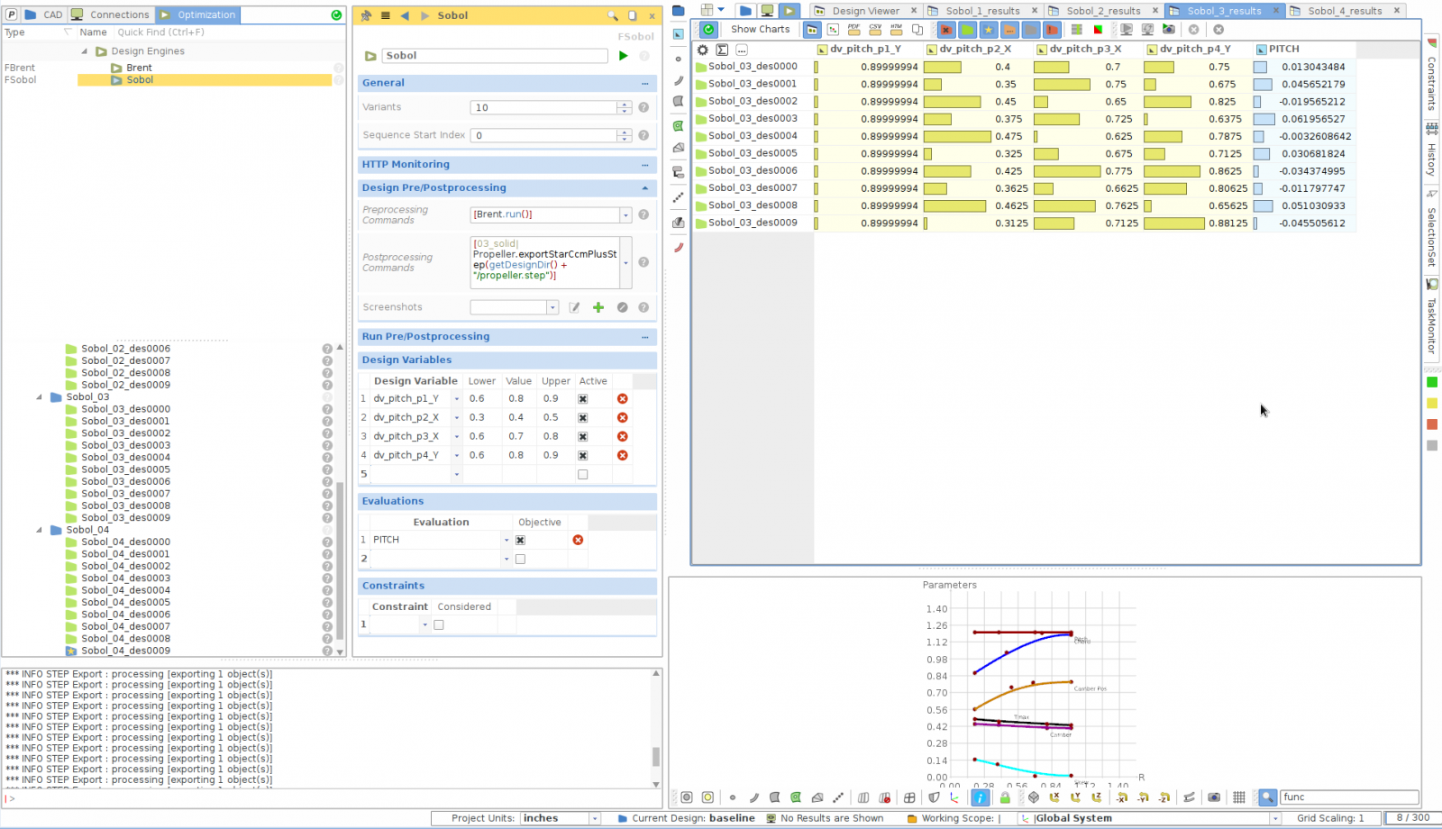
Hi Suraj,
2) Please use the command below,
[03_solid|Propeller.exportStarCcmPlusStep(getDesignDir() + "/propeller.step")]
Because you have not assigned any Software Connector; no geometry will be exported unless you specify explicitly.
You have to use this command in your Design Engine's "Design Pre/Postprocessing" menu, under the Postprocessing Commands.
So after the creation of each new design, the command to export the geometry to the relevant Design Directory will be executed.
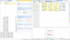
1) In your setup, there was no objective assigned.
Please review the attached project and the picture.
Cheers
Ceyhan
propeller_PD_0.8_highTipThickness.fdbc.tar.gz
-
Hi Hamidreza,
Can you give some more information with regards to your project?
If I am not mistaken, Poseidon is not as much supported by DNV GL as before.
Cheers
Ceyhan
-
Hi Kerstin,
Besides Paulo's explanation, I would strongly suggest you to create a constraint for your optimization.
Let's say you have created the parameter;
IF(<Brepname>.isValid(), 1, 0)
then you can create an equality constraint that will be assigned to, let's say your Sobol, and you can use it for the visualization of your failed/valid designs. If failed then no further steps will be taken and it will pass to the next design.
Do you obtain a lot of failed designs? Maybe you share some pictures of your geometry.
Maybe we should focus on decreasing the number of failed designs.
Cheers
Ceyhan
-
Hi Suraj,
When you run any optimization sequence, the geometry for each new design will be automatically saved in the corresponding folder structure with respect to the export type defined previously in the Software Connector phase.
Say you are running a Sobol sequence; let's say the first created sobol sequence is Sobol_01
Within your CAESES project folder,
In the folder;
01_sobol / Sobol_01_des0000 <depending on the design, let's pick the first one> /Runner
You will find the geometry that you are seeking for.
Cheers
Ceyhan
-
Hi Lexi,
Is it possible that you share the project file if it is not confidential?
You can send the fdb/fdbc file to erdem@friendship-systems.com, so I can give a look.
Cheers
Ceyhan
-
 1
1
-
-
Hi Matt,
This looks strange. I have no problems to make it work.
Please let me know when you may be available, so that we can arrange a web-meeting and I can check your setup.
You can send me an email to;
erdem@friendship-systems.com
Cheers
Ceyhan
-
Hi Matt,
Can you please verify if you did the following change on your Ansys installation, as mentioned in the CAESES Act app installation instructions?
In the installation directory, edit the following file:
Windows: /vXXX/Addins/ACT/bin/Win64/TransferTypeDirectPropertyAccessList.xml
Linux: /vXXX/Addins/ACT/bin/Linux64/TransferTypeDirectPropertyAccessList.xmlAdd the highlighted line:
<TransferTypes>
.....
<TransferType>FEMSetup</TransferType>
</TransferTypes>Cheers
Ceyhan
-
Hi Matt,
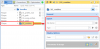
Within your project, in the feature definition "importpointdata" seems you were creating a tableViewer which in fact is a gui operation.
When disabled everything began to work with no problem.
Another remark is that within the same feature definition you have created an FBool with a name "visible" which is a used name by the system , already giving an error. I have changed that one with "show".
Please let me know if you encounter any problems.
Note: I have changed the folder structure, please do not forget to recreate your fsc file and close Caeses while workbench is running.
Cheers
Ceyhan
-
Hi Josuas,
with a rather quick search I came up with the term Grouches Spoiler.
Cheers
Ceyhan
-
Hi Matthew,
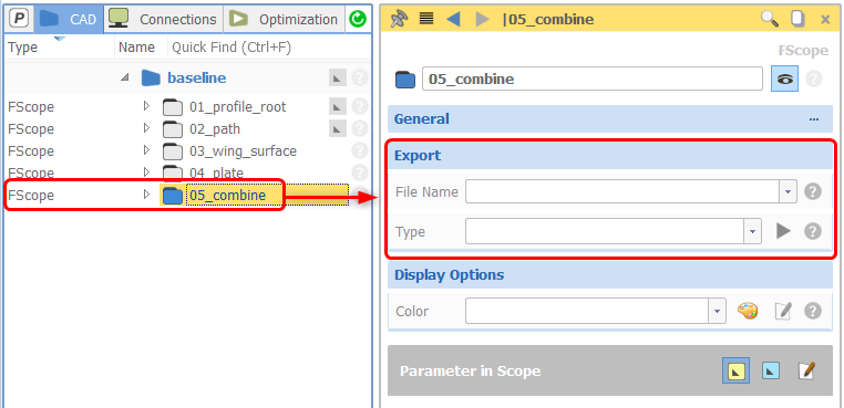
When I have checked the project the first point observed is that, your export folder is not provided with the geometry export type and name information.
Please also check the ANSYS ACT App tutorial within CAESES about how to use and install the app.
Cheers
Ceyhan
-
Hi Suraj,
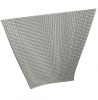
After some checks on the created stator blades I have figured out that the distribution of the control points on the created airfoil curve was changing drastically at some point.
This was creating a problematic surface that might lead to failed solid creation.
The bug is already solved in the new version which will be released soon. Meanwhile I can provide you a workaround.
Please find attached the project file with the updated feature definition.
Note: please update the thickness file path in the feature definition accordingly
Cheers
Ceyhan
-
Hi Suraj,
Please find attached the updated project file.
One thing that I have figured was that the parameter "chord" in the feature definition was named as Xchord which I have changed it back to chord.
Not a cause but I have also added a string parameter where you only have to specify your input file path. It would be easier in case you change the file location instead of editing the feature definition.
Please update the stringParameter inputPath accordingly and let me know if you still have some problems.
Cheers
Ceyhan
-
Hi Suraj,
Can you please compress and attach the thickness distribution txt file.
I want to give a look at your project.
Cheers
Ceyhan
-
Hi Mr Suraj Pawar,
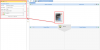
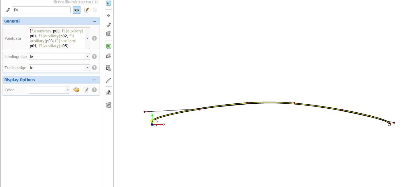
From the picture you have attached I can see that a curve is assigned for point data.
Instead of a curve a set of points should have been assigned
Please see the attached picture.
Cheers
Ceyhan
-
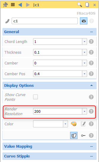
Dear Mr. Suraj Pawar,
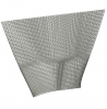
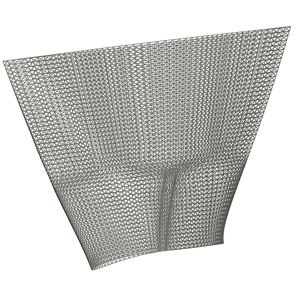
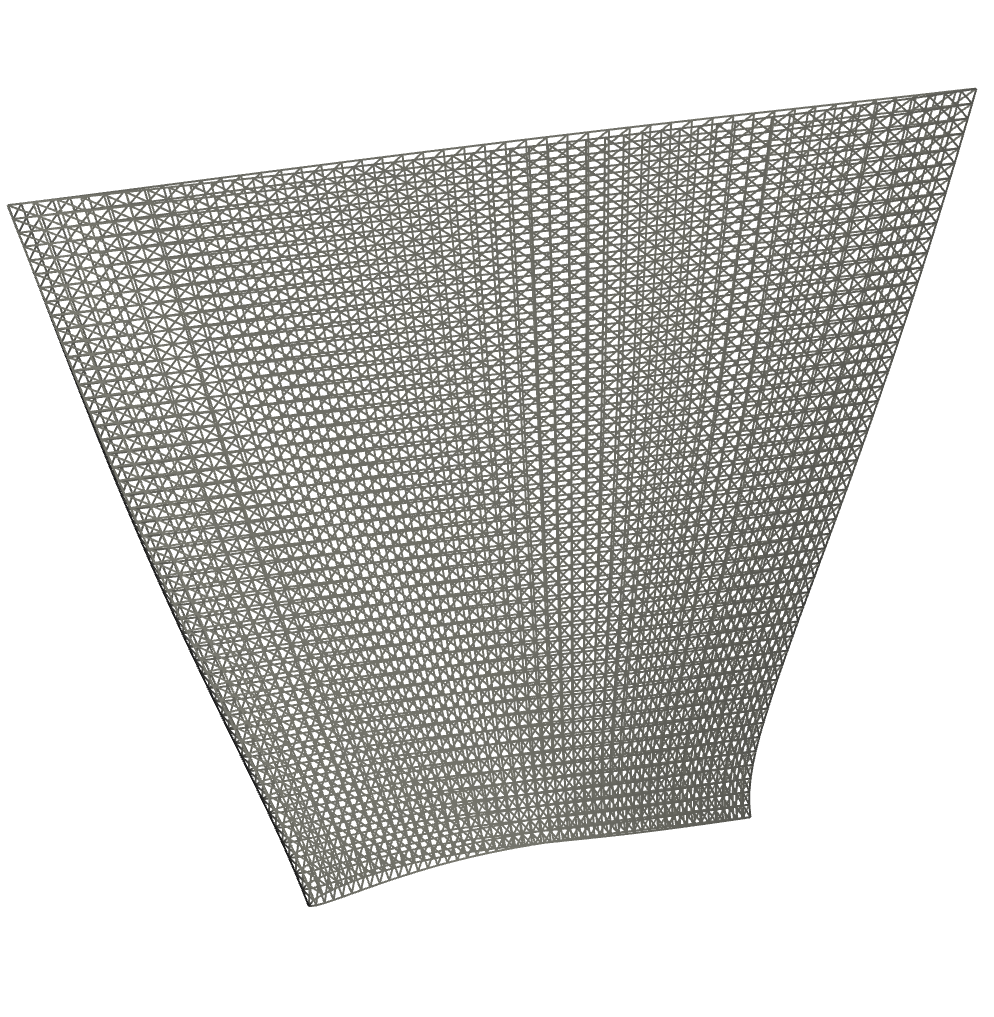
This is a case caused by the visualization parameter of the curve being relatively low.
If you increase the " Render Resolution " value within the related curve's menu, you will observe that the way the curve looks will be smoother.
By the way this does not affect the geometry when it is exported.
For your second question, do you want somehow extrude your profile not along a line but along a curve?
If it is the case, you can simply define your extrusion profile and then under " Surfaces ", create a "Sweep Surface"
Cheers
Ceyhan
-
Hi Amin,
I checked your file and seems changing the parametrization to "unit speed" for the total contour did the trick.
For both start and end profile curves please try to change the parametrization value from default to unit speed. You can find it if you expand the "general" menu.
Please let me know if you experience any problem.
Cheers
Ceyhan
-
1
-
-
Dear Amin,
Can you please add your CAESES file so that I can have a quick look.
Cheers
Ceyhan

Check Validity result
in Variation & Optimization
Posted · Report reply
Hi Kerstin,
As you have mentioned, the function "isValid" only checks whether the BRep is created or not. Right now, on the current release version, we have no implemented command for the user to calculate the number of warnings or the type of warnings that can be used in a parameter. However, on the next release version, the user will be able to have both the number of warnings and the list of warnings from which one can check for specific warnings.
For your geometry you can still have two BReps, one to export and one for validation. I would recommend you to create a BRep from the geometry that you would like to export and add the command "close planar holes". Afterwards you can use it to calculate volume or check for number of openEdges.
Cheers
Ceyhan