


Ceyhan Erdem
-
Content Count
196 -
Joined
-
Last visited
-
Days Won
11
Posts posted by Ceyhan Erdem
-
-
Hi Mlysyshyn,
sorry for the late answer, I will check your model tomorrow and will write you as soon as I find the problem.
Cheers
Ceyhan
-
Hi Mlysyshyn,
Can you please share your project file if it is not confidential?
You can also send it to erdem@friendship-systems.com
so that I can give a look at your SoftwareConnector setup.
Cheers
Ceyhan
-
 1
1
-
-
Hi Elena,
Sure feel free to ask any related questions.
In case you need a web-meeting please send an email to erdem@friendship-systems.com, defining your questions as well.
Yes, you have to create manually the *.bat file. Just create an empty file and change its extension to .bat.
Cheers
Ceyhan
-
Hi Mlysyshyn,
I can see that the files are are moved to their related locations.
Can you please share any console output?
Or some OpenFoam logs where the problem can be tracked?
Cheers
Ceyhan
-
1
-
-
Hi Elena,
As mentioned earlier when the ACT App is used CAESES only acts as a parametric geometry provider for ANSYS Workbench. Hence you cannot benefit from the CAESES optimization tools but have to rely on the ANSYS Optimization/ANSYS optiSLang.
The connections among the ANSYS tools within Workbench is quite straightforward by just linking the related components however you would have some little issue when you would like to include some non-ANSYS tools unless you write your own app.
When you use CAESES Software Connector, you have the capability to link every tool, in case they support scripting.
Coming to your questions;
1) You have to keep in mind that when you are running an optimization/DoE, each time a new design folder is created including the files in your Software Connector.
So let's say CAESES is working on the design# 142. The CAD geometry and all the scripts related need to be located to the specific folder.
The scripts where your local path is mentioned has to be made dynamic by getResultsDir()/getDesignDir(), etc.. so that each time CAESES copies the script file to the new design folder, the paths are updated.
You do not have to make the ANSYS installation path as dynamic since it does not change from design to design. But sometimes is useful when you would like to use your CAESES project on another computer. So by just changing once the path you will be able to update your script on several locations, if any.
2) As mentioned on item 1, as a must you have to update your relative paths. Do not forget that the way CAESES links the Softwares is through scripts. The Computer or the Softwares would not know where the files they are looking for are unless it is explicitly mentioned within the scripts.
3) You just would need one script/journal file for ICEM CFD that includes all the commands necessary to build your mesh. You can create the necessary file within ICEM CFD automatically.
4) *.bat file is a windows batch file containing windows/dos commands however *.sh file is a unix shell script file that contains a series of unix commands.
If your operating system is Windows, your main batch file that includes all the commands to run the tools should be a *.bat file. And in the case of Linux, it should be *.sh.
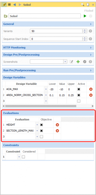
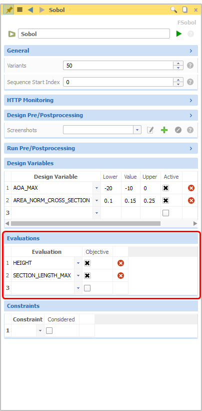
5) Within the menu of your optimization engine, you can include your desired objective functions under Evaluations.
Cheers
Ceyhan
-
Hi Elena,
The ACT App serves to bring CAESES as a parametric geometry provider into the ANSYS Workbench platform. By using the tool, one can get, besides the geometry, the parameter set and the boundary names defined in CAESES. In this case, ANSYS Workbench is the platform that controls the workflow.
However when you use the scripts in CAESES, through Software Connector, then CAESES becomes the platform that controls the workflow and the Meshing tools or the CFD/FEM analysis tools would work standalone either in batch or with gui.
Can you please let me know in more detail, what kind of problems you are facing?
We can also have a quick web-meeting so that you can share your screen.
Cheers
Ceyhan
-
Hi Armagan,
Your fsc file seems to be with no problem.
I would like you to check,
1) if the path mentioned on the second line is still correct.
Please be sure that your fdb/fdbc file is still at the same location. If not either recreate an fsc file or just change the path.
2) if your license allows you import acis file. You can easily check this by trying to import an acis(sat) file in DesignModeler or SpaceClaim.
3) if a geometry is exported in CAESES. Maybe your geometry has failures and it creates an sat file with no data.
Please let me know the results. If the problem is still not resolved we can have a quick web-meeting as well.
In that case please write an email to erdem@friendship-systems.com
Cheers
Ceyhan
-
Hi Armagan,
Can you please share your fsc file?
Cheers
Ceyhan
-
Hi Armagan,
Can you please share your fsc file?
Cheers
Ceyhan
-
Hi Maria,
The menu that you have on the screenshot belongs to a B-Spline curve. There, you can input a list of control points to modify your curve.
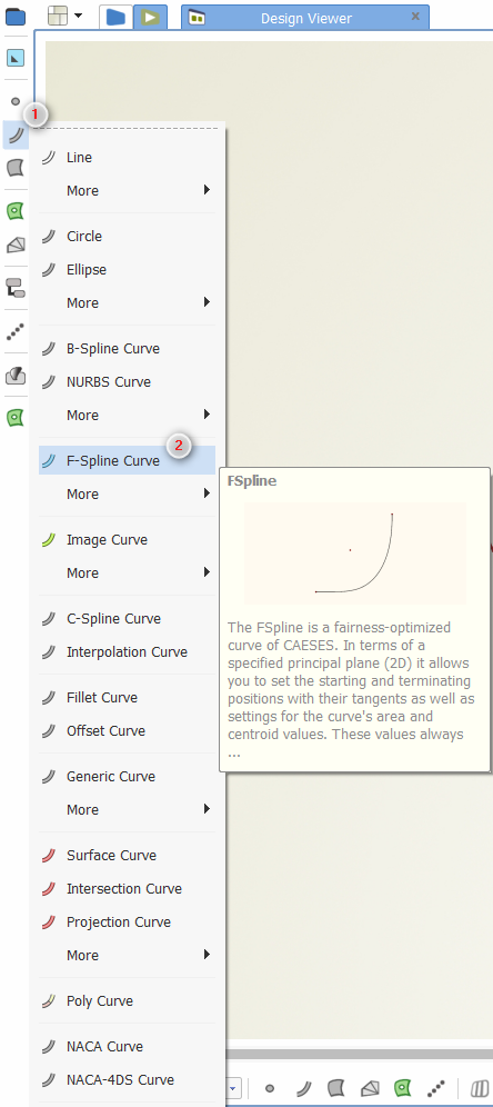
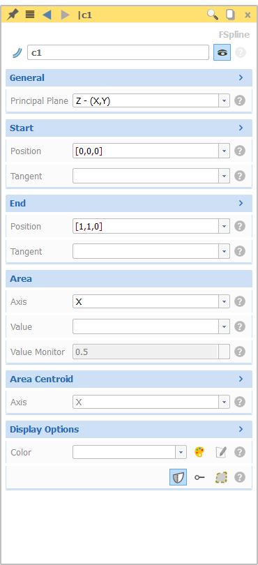
Is it possible that you are looking for an F-Spline curve, where the user is requested to provide a start point, an end point and corresponding tangency values?
Cheers
Ceyhan
-
Please find below the point cloud data that I have used. As I said you can modify the "ReadData" feature Definition wrt your needs.
1.000000 0.000000 0.000000
0.950200 0.008912 0.000000
0.900500 0.017584 0.000000
0.850700 0.026352 0.000000
0.800800 0.035078 0.000000
0.750500 0.043616 0.000000
0.700900 0.051586 0.000000
0.650800 0.059006 0.000000
0.600600 0.065628 0.000000
0.550300 0.071270 0.000000
0.500000 0.075742 0.000000
0.449600 0.078800 0.000000
0.399200 0.080180 0.000000
0.348800 0.080320 0.000000
0.300000 0.078760 0.000000
0.250000 0.076000 0.000000
0.200000 0.071660 0.000000
0.175000 0.068800 0.000000
0.150000 0.065400 0.000000
0.125000 0.061386 0.000000
0.100000 0.056496 0.000000
0.075000 0.050484 0.000000
0.050000 0.042726 0.000000
0.037500 0.037762 0.000000
0.025000 0.031500 0.000000
0.012500 0.022728 0.000000
0.005000 0.014580 0.000000
0.002000 0.009474 0.000000
0.000000 0.000000 0.000000
0.002000 -0.005484 0.000000
0.005000 -0.008754 0.000000
0.012500 -0.013108 0.000000
0.025000 -0.017282 0.000000
0.037500 -0.020250 0.000000
0.050000 -0.022680 0.000000
0.075000 -0.026610 0.000000
0.100000 -0.029720 0.000000
0.125000 -0.032260 0.000000
0.150000 -0.034368 0.000000
0.175000 -0.036120 0.000000
0.200000 -0.037440 0.000000
0.250000 -0.039360 0.000000
0.300000 -0.039900 0.000000
0.348800 -0.039420 0.000000
0.399200 -0.037900 0.000000
0.449600 -0.035574 0.000000
0.500000 -0.032588 0.000000
0.550300 -0.029338 0.000000
0.600600 -0.025976 0.000000
0.650800 -0.022670 0.000000
0.700900 -0.019420 0.000000
0.750500 -0.016202 0.000000
0.800800 -0.012994 0.000000
0.850700 -0.009776 0.000000
0.900500 -0.006536 0.000000
0.950200 -0.003272 0.000000
1.000000 0.000000 0.000000
-
Hi Christian,
When I deal with an airfoil I always start with one that has a chord length of 1.
So in most databases the airfoil point data has an aligned chord to x-axis that has a length of 1, starting from 0 and ending at 1.
You can either modify the feature "parameterize curve" to fit into your dimensions, or scale the airfoil data so that it has a chord of 1 and aligned to x axis.
Cheers
Ceyhan
-
Hi Christian,
Please find the attached project.
Please note that this is rather a simple case that can further be improved.
Please let me know if you have further questions.
The feature that reads the point data needs a file where x y z coordinates are provided only. You can modify the feature with respect to your needs.
Cheers
Ceyhan
-
Hi Christian,
What you you have to do first is to redefine the airfoil curve as a combination of thickness distribution and camber distribution curves.
Parameterizing these two curves in an automated way would provide you a way to approach your goal.
Let me prepare a simple project where one can read point cloud data; convert it to an interpolation curve; redefine it as camber distribution and thickness distribution curves and finally parameterize those curves in a simple and easy way.
If I find time today, will be posting here.
Cheers
Ceyhan
-
Hi Bastian,
If you would like to, you can send your project to erdem@friendship-systems.com
I can take a look in your model.
Cheers
Ceyhan
-
Hi Bastian,
That is a good question indeed.
In a BRep the number of edges for a geometry variation of a certain object does not necessarily remain constant. Depending on your split method it may vary.
So I would suggest you to use the source, which most probably is a surface.
mySurface.getEdge1() or 2,3,4
would provide you the necessary edge.
If you have further questions, please let me know.
Cheers
Ceyhan
-
Hi Zhongwen,
Can you please give a try the attached Feature Definition?
For the time being the dropdown menu contents are not suitable for the user to be modified. But I can suggest you a workaround that may help you for the time being.
Please let me know if you have further questions.
Cheers
Ceyhan
-
Hi Elysse,
Is it possible for you to share your project file, so that I can give a look?
Cheers
Ceyhan
-
Hi Steven,
Good to hear that you have resolved it.
Please let me know if you have further questions.
Cheers
Ceyhan
-
Hi William,
A "Geometry" component cannot be linked with another "Geometry" component within Ansys Workbench. It can be linked to Meshing, etc.. components however.
The so called "Ansys Geometry" component within ACT app acts in a same manner as a default Ansys Geometry component.
And I would not suggest and guarantee the success of linking the "Caeses Geometry" component with any other components. Please use the "Ansys Geometry" component for linking purposes.
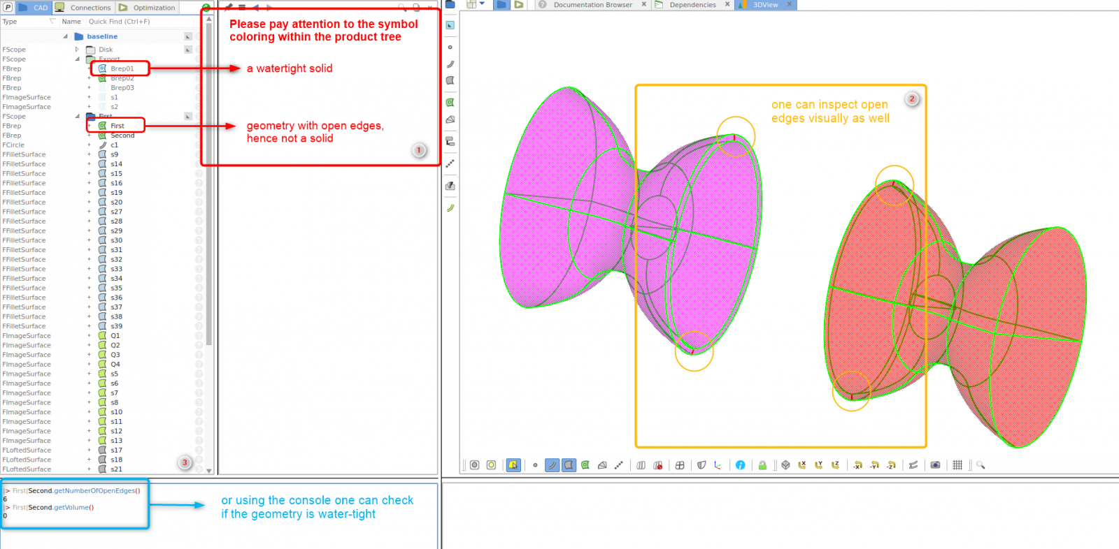
What I can observe from your project file is that when you play with the above mentioned parameter, some unconnected edges appear. You can see them as red curves within the BRep.
Please check the attached picture for some hints.
Cheers
Ceyhan

-
Hi Chun,
As mentioned on the previous post, you should be having Shipflow installed on your computer. If that is the case you can find the the mentioned file as specified within the referred tutorial.
Please let me know if you have further questions.
Cheers
Ceyhan
-
Hi Steven,
Please check the attached project.
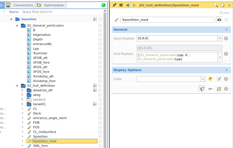
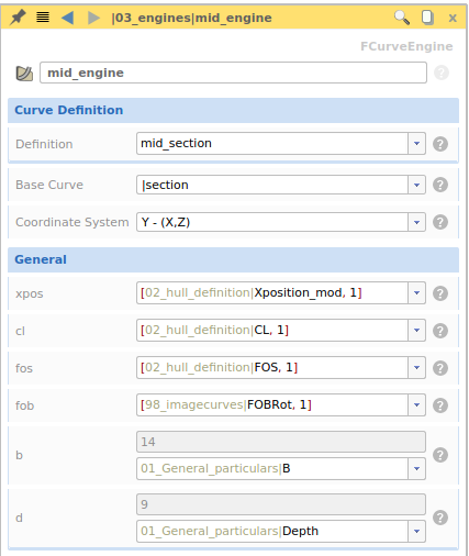
I have observed that, your function curve which is supposed to provide the x-position is not defined correctly. What the curve engine does is from the abcissa value (depending on your coordinate system) obtain the ordinate and provide this value as an input.
I have created a new function curve and got rid of the scale parameter.
Coming to your second question, when I use the command;
CL_midsurface.ft(0,20) ; I assume 20 is the starting x-position
I obtain the correct value for position parameter which is 0.
Cheers
Ceyhan

-
Hi William,
Sorry for the late answer, I was on vacation last week.
Can you please link the "ANSYS Geometry" but not the "CAESES Geometry" task to the "Geometry" task of the "Static Structural" system?
The "CAESES Geometry" is only an input task and would not work properly as desired if linked with any other system/task.
The reason to have the "ANSYS Geometry" is to create the so called "Named Selections" for boundary names, calibrate the geometry for different unit systems, etc..
Depending on your preferred Geometry tool within ANSYS Workbench (Under Workbench options, this can be modified) you can review the geometry either on "SpaceClaim" or "DesignModeler".
Please check the instructions how to utilize the ACT App, which can be found under CAESES Tutorials.
Please let me know if you have further questions. We can arrange a web-meeting.
Cheers
Ceyhan
-
Hi Gabrielle,
There seems to be a problematic fspline curve "bottom" within your Feature Definition "AFT".
The Area value seems to be not correct which causes the problem.
When I dig into the feature definition I can see that you are directly assigning the Sectional Area Curve value that you obtain from the computation to the fspline area. But you also have to take into consideration the normalization factor.
Please check the attached project and let me know if you have further questions.
Cheers
Ceyhan

OpenFOAM connection error
in Software Connections
Posted · Report reply
Hi Mlysyshyn,
Please find attached the modified version.
Some modifications I have performed;
1) Within the Runner for the "Local Application" I have selected the AllRun.bat which I have created. Please note that I am not using any arguments.
2) The RunAll.bat executable includes commands within the "C:\OpenFOAM\19.10\cygwin64\Cygwin.bat" executable (lines 4-9) and the path to my script file which is the AllRun.sh (line 9)
3) Finally made a little modification to the script file.
The final configuration seems to be working but didn't pay attention to the OpenFoam setup.
Cheers
Ceyhan
Sduct_with_openfoam_2_FSYS.fdbc