


Ceyhan Erdem
-
Content Count
196 -
Joined
-
Last visited
-
Days Won
11
Posts posted by Ceyhan Erdem
-
-
Hi Greychen,
Please be sure that you are using the latest version of the ACT App, that is shipped with Caeses v5. You can find it within the <Caeses installation folder>/etc/ansys

Yes, after the boolean operation C will inherit the colors from A and B.
Cheers
Ceyhan
-
Hi Graychen,
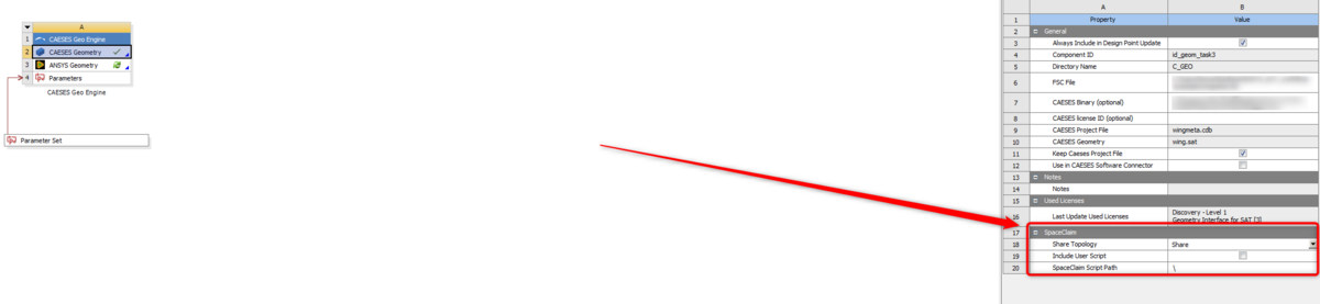
That option exists within "Caeses Geometry". B2 in your case. Please check it before updating the component.
I believe your default geometry module is set as SpaceClaim. I will recommend you to go over the tutorial with regards to Ansys Workbench Connection in Caeses v5.
If you have set the correct color coding in A and B, when you perform a boolean, you should be having the propagated colors in C.
Please assign a color to your entire fluid volume.
Also do not forget to make a change in SpaceClaim that is mentioned within the tutorial.
Cheers
Ceyhan
-
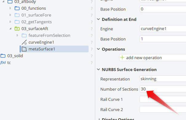
Hi Carlos,
You had to issues that caused the problem.
1. The Z value of point1 for the curve weightStart was 0.
It should be changed to 1 or to some other reasonable value.
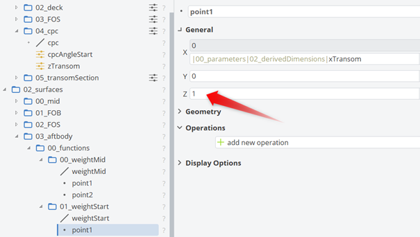
2. The default value of Number of Sections in MetaSurface is 15. Increasing this number would improve the surface resolution. For example, 30 in this case.
Cheers
Ceyhan
-
Hi Carlos,
When you are creating a feature definition by the selection of entities through gui, all objects selected become a definition within your feature. However any unselected entity, if dependent to your selected objects, become an argument(input) for your created Feature Definition.
Also, seems like you have performed an "Execute Definition" operation with no inputs maybe?
Please try to perform "Create Feature" instead of "Execute Definition", which will help you to understand how it works.
Cheers
Ceyhan
-
Hi Graychen,
I can see that you are using Caeses v4.*. Is there a specific reason for that?
The current ACT version which is shipped within Caeses v5 installation files may not be supporting the full features with Caeses v4
1. I will highly recommend you install Caeses v5 together with the shipped ACT app. There you can modify the project units which will the transferred to downstream.
2. If you are using SpaceClaim as your default geometry editor in Ansys Workbench, then I will recommend you create a script file for SpaceClaim that will generate the domain creation and then the subsequent boolean operation. You can provide the script file to the ACT App, which you can see within options menu.
However if you are using DesignModeler, you do not have to provide a script. Because in this case only the geometry and the Named Selections are changed. And the new entities created afterwards remain there.
But I will recommend you to create the complete fluid domain in Caeses, providing the necessary colorings as well.
And if you are going to link the Caeses created geometry to any other tasks, please use A3, which is the geometry with the included Named Selections.
3. Basically what you have there is a surface. You can create a trailing surface using a ruled surface. It is a surface type that you have to provide two curves. In your case the trailing curves of pressure and suction side would do the job.
Then you can add those into a BRep to start creating a water-tight geometry. I don't know your design but then a simple "Close Planar Holes" or a "Solid From Intersections" operation with the help of hub and shroud surfaces should do the trick.
I will recommend you to go through the tutorials and switch to Caeses v5.
Cheers
Ceyhan
-
Hi Carlos,
It is difficult to guess from the picture provided.
If it is not confidential please send the project file to erdem@friendship-systems.com so that I can give a closer look. If it is not possible to share then please let me know your availability so that we can arrange a web-meeting.
Cheers
Ceyhan
-
Hi Carlos,
It is quite difficult to see what is written for the input location corresponding to "Tp"
Basically tp is a value varying from 0 to 1 and it defines the parametric location within the curve. 0 being the start and 1 the end.
I guess you have used a combination of ft and fv ending up having the parametric value. I can see a value is printed over the command which is the result.
Can you please let me know what makes you think the command is not working? Do you think it is providing an incorrect value?
If so, can you please be more specific in order to understand?
Cheers
Ceyhan
-
Hi Carlos,
I will highly recommend you perform the basic tutorials with regards to parametric geometry creation.
Under;
Tutorials > Basics
You can find the necessary tutorials/information on how to proceed in your model.
Cheers
Ceyhan
-
Hi Carlos,
Please right click on the black ribbon and select the view you would like to reopen.
Cheers
Ceyhan
-
Hi Carlos,
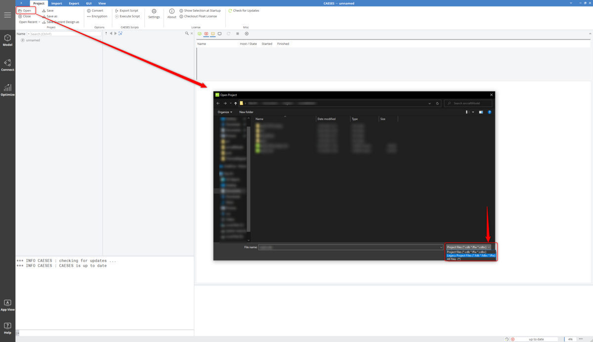
Please proceed as usual to open the project by selecting "open" and then from the pop-up window using the drop down list select "Legacy Project Files".
Now you should be able to see fdb/fdbc extension files.
Cheers
Ceyhan

-
Hi Etienne,
Thank you for the data but the information provided is missing.
Can you please provide the gl info again?
The data in the console should start with
"
***********************************
*** Context information ***
"
Secondly; for the future, I would recommend you to use the Caeses Helpdesk for quicker and better support;
Cheers
Ceyhan
-
Hi Etienne,
I need a bit of clarification. Are all your displayed surfaces shown in red color or only the selected surfaces by you are showing this behaviour?
Cheers
Ceyhan
-
Hi Rizuan,
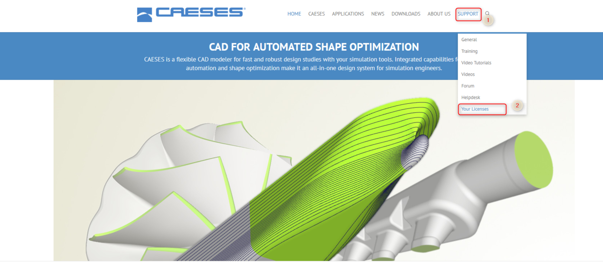
On our webpage please go to Support > "Your Licenses"

Once logged in, please check the status of your license. By clicking on the manage button on the right side, you may have the option to release a hanged webfloat slot.
Please let me know if this resolves your problems.
Cheers
Ceyhan
-
 1
1
-
-
Hi Carlos,
On our webpage please go to Support > Helpdesk. Or you can reach it directly through "https://helpdesk.caeses.com"

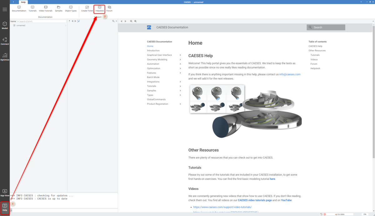
Alternatively, once you start using Caeses 5, you can reach the Helpdesk directly through the Caeses gui.

Cheers
Ceyhan
-
Hi Carlos,
That does not look nice.
Can you please try to restart Caeses.
Please create a ticket in the Helpdesk with regards to your Caeses 5 problem. We can try to figure out the problem and take some measures if need to be.
I strongly advice you to use Caeses 5.
Cheers
Ceyhan
-
Hi Nuttarat,
Can you please let me know your availability so that we can arrange a web-meeting and I can check your setup.
You can write to erdem@friendship-systems.com
Please take into consideration that we are locate at Central European Time Zone.
Cheers
Ceyhan
-
By the way, I have just figured that you are using Caeses4.
Is there any specific reason for that?
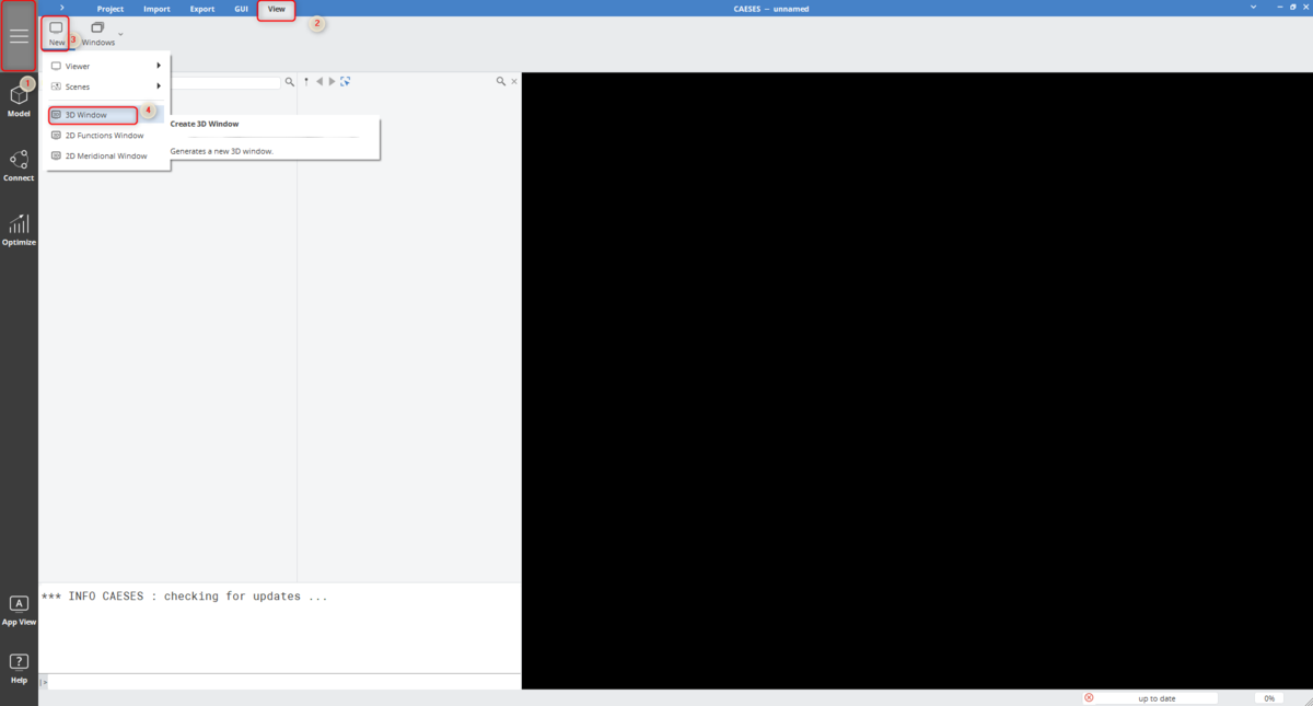
In your case, I guess the path should be View > New > 3D Window
Cheers
Ceyhan
-
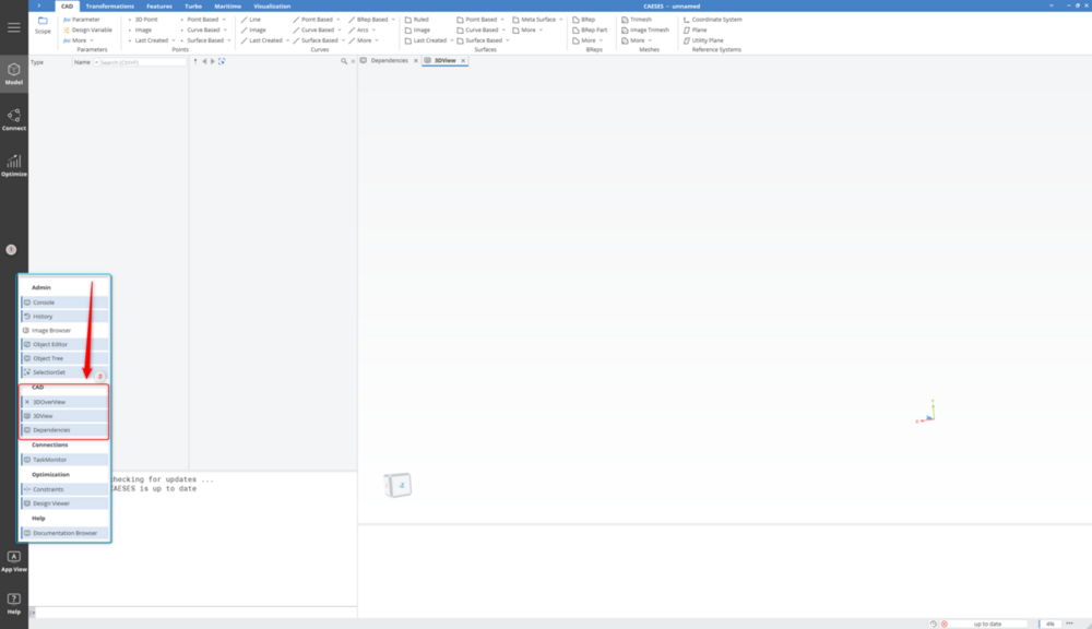
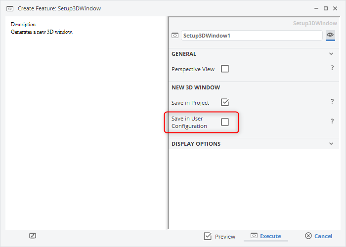
Hi Carlos,
On the side bar please please click the top button and then follow the steps;
View > New > 3D Window

In the opened menu, please select "Save in User Configuration" and click "Execurte". This will open a 3DWindow and enable Caeses to load the new 3DWindow whenever Caeses loads.
Please let me know if this resolves your problem.
Cheers
Ceyhan
-
HI Winson Du,
As mentioned on an earlier post of yours, please connect "ANSYS Geometry" to "Mesh" component within Fluid Flow not "CAESES Geometry" to "Geometry".
Please check the tutorial with regards to CAESES Workbench App.
Cheers
Ceyhan
-
Hi Winson,
I will recommend you checking the "CAESES Geo Engine for ANSYS Workbench" tutorial under Help>Tutorials>Software Connection where every detail is described.
Basically the CAESES Geometry Task is connected to ANSYS Geometry where the Named Selection creation process is performed. Then you can connect the ANSYS Geometry with any downstream consumers.
Cheers
Ceyhan
-
Hi AlexisNav,
I will recommend to check the tutorials with regards to Software Connection within CAESES.
Locating a script file inside the "Input Files" quarter does not necessarily run it unless it is specified within your executable.
Once you go over the tutorial files, please let me know if your problem is still unresolved.
Cheers
Ceyhan
-
Hi Lasse,
Great. Please let me know in case the issue is not resolved then.
Cheers
Ceyhan
-
Hi Lasse,
Would you like to have a quick web-meeting?
Tomorrow I will be available after 1pm (CET). You can share your screen and it would be easier for me to understand the question and resolve it.
Please send an email to me (erdem@friendship-systems.com) mentioning when you may be available.
Cheers
Ceyhan
-
Hi Lasse,
What you are performing is creating a surface by sweeping a profile all through a path. The red curve that you are visualizing(parallel to the path) , I believe, is due to the start/end location of your profile/s.
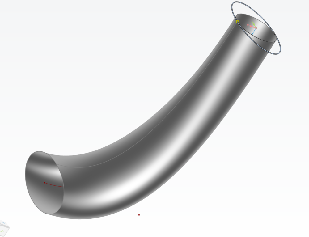
In a surface you should have 4 main edges and the red curve is in fact of the main edges that define the surface. The other ones are the start and the end profiles(relocated).
Please let me know if you need further assistance.
Cheers
Ceyhan


Some questions about CAESES ACT、 workbench and propeller feature
in Variation & Optimization
Posted · Report reply
Hi Donhung,
Please check the picture below;
I will recommend you to revise the Caeses tutorial files.
Cheers
Ceyhan