


Matthias Maasch
-
Content Count
108 -
Joined
-
Last visited
-
Days Won
1
Posts posted by Matthias Maasch
-
-
Dear Mehmet,
this is typically the argument you need to run star with an already existing file. : "-batch YOUR_JAVA.java -power -podkey YOUR_PODKEY YOUR_SIM.sim". Replace all YOUR_... with the acutal file names and your podkey string.
Step: Yes, it is possible. If you go to File > Export > ... you can see that we indicated STAR-CCM+ compatible export types.
Regards
Matthias
-
Hi Xavier,
unfortunately, CAESES doesn't offer such functionality. If you rely on CAESES you would need to create a feature code that does the calculations for you.
If, however, you have a license for Bentley's Maxsurf Stability (former Hydromax) you could use an already existing feature code that connects to Maxsurf automatically. This particular feature is called "Equilibrium" and can be found in our online store under Hull Design > Connections > Hydromax > HydroMaxEqulibrium.
Please note that this feature needs a change in line 22 from "if (NOT(Hydromax.setComObject("Hydromax.Application")))" to "if (NOT(MaxSurf_Stability.setComObject("BentleyStability.Application")))" in order to be able to launch Maxsurf Stabilty.
Let me know what you think.
Cheers
Matthias
-
Hi Mohamad,
using the Generic Blade you can either apply skew values via distance (as a linear dimension) or via angle. When you extend the header "Radial Information" in the Object Editor you can switch the Skew Representation.
Cheers
Matthias
-
Hi Moises,
please find attached a revised version of the feature. I added a few lines at the beginning of the code:
if(!(file)) break() endif
I am guessing CAESES "crashed" on your machine (in my case it doesn't crash but runs into an infinite loop which gets stopped by CAESES automatically after 10000 loops) because after creating the feature the input file is not set. The code lines above are helping to avoid this infinite loop.
I hope that solves your problem.
If not, let me know.
Cheers
Matthias
-
Dear Mohamad,
please take look into the text book "Principles of Naval Architecture Vol II", page 188/189. There you can find what you are looking for.
Cheers
Matthias

-
Hi Maruf,
I checked the files you send and I would suggest to change a few settings. Please note that I don't have Shipflow available right now and that my suggestions are based on my previous experience with Shipflow. I am also not familiar with the very latest version of Shipflow.
General remarks: Please read through the Shipflow tutorial "SHIPFLOW CFD Analysis" which comes with CAESES. There you can study how to create a simple XPAN setup using a SurfaceGroup as geometry input. As Shipflow is an external code it comes with its own tutorials which you should consider to study as well.
For the file cargo_2:
1) The ship geometry has a length of 1800 units (either m or mm). In your offset settings you provide a length of Lpp=45. Both numbers should corelate.
2) Since you have the geometry in CAESES you could follow the CAESES tutorial - create a SurfaceGroup (in addition you could create an ImageSurfaceGroup and apply a scaling to it to scale down your ship) and use the command YourImageSurfaceGroup.exportIGES("YourHullName").
3) Furthermore you don't provide commands such as xaxdir, ysign, xori and zori. I am guessing you should set those values.
For the file container:
1) Consider all the above suggestion for this case as well.
For more support please contact support@flowtech.se.
Best Regards
Matthias
-
 1
1
-
-
Hi Maruf & Joerg,
please let us continue the discussion in the following post: Here!
Thanks
Matthias
-
1
-
-
Hi,
could you please send the CAESES file including your IGES geometry? If you don't want to share it here (in public) you're welcome to send it via email.
Cheers
Matthias
-
1
-
-
Dear Maruf Uddin,
according to your screenshots the sub-routine xoffgen.exe (part of Shipflow) fails in converting the IGES into offsets. If the only thing you changed is the IGES file (plus any dimensional properties given in the Shipflow settings (Lpp, draft,...)) then I would say the error occurs due to the quality of your IGES. I think it is unlikely that CAESES itself is the problem.
Please note that this Forum doesn't provide Shipflow support (unless a user is keen and able to help you). For more help please contact support@flowtech.se.
Best Regards
Matthias
-
1
-
-
Hi Nabila,
the file you send doesn't contain a Lackenby Shift. Could you please check and send the correct file.
Thank you
Best Regards
Matthias
-
Dear Nabila,
could you please share your Lackenby settings or your CAESES project. If you don't want to share it here in the Forum you could send it via email.
Best Regards
Matthias
-
1
-
-
Hi Hugo,
Please note that this Forum doesn't give support for Shipflow issues, although simple problems can be solved due to our experience.
Unfortunately I have no experience with this Shipflow module. In order to get help please contact support@flowtech.se.
Best Regards
Matthias
-
Hi Bodo,
I hope I understand you correctly: You need the maximum x position of the curve? To solve your issue I used the most straight forward way I could think of and it works. However, it isn't really different from yours and both should work.
What I did: Select the target curve and create a point. This point is automatically on the curve defined by the parameter tc. In tc I wrote "targetCurve.getmax(0,1)". The "1" in the getmax command gives you access to the curve parameter at the max position of the axis directly. So, what you need is t=targetCurve.getmax(axis,1).
Your way adds one more step by using the ft command. When substracting a little correction c3.getPos(c3.ft(0, c3.getMax(0) - 0.00017)):x it comes close to the actual value.
I assume when doing it like you did a numerical error messes it up. Maybe one of my colleagues can give a proper answer to that issue.
Regards
Matthias
-
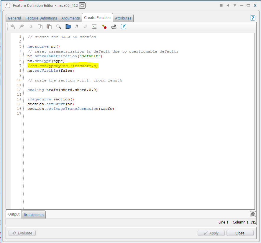
Dear Gabriel,
The profile type has to be defined within the feature definition which is used in the curve engine. Please see the screenshot below.
In the feature line 7 initially defined the profile type by tc, liftcoeff and a. Another option would be to define the type by actually choosing the provided types. I implemented this option in the feature in line 6.
In the attached sample project you are now able to choose the NACA type in the curve engine |00_blade|NACA. If you have problems to understand the meaning of curve engines and features, please do some tutorials about Features and Meta Surface.
Cheers
Matthias
-
Hi Hamidreza,
please check out our feature Features > Hull Design > Lines Plan from Surfaces. Before executing the feature create a 2D Window via View > New > 2D Window Setup. This will create a proper lines plan.
Another solution could be to simply create sections using the surface sections visualisation in the display options. There you can visualise sections in x, y and z plane. You could create those, then set the 3DView into section mode (bottom tool bar) and take a screenshot in x, y or z plane
I am not quite sure how to present the created compartments. Is there any standard procedure? You could create sections at the specific positions and give them a different color.
Best Regards
Matthias
-
Dear Yung-An Chu,
this error message is produced by Shipflow, your external CFD software. This Forum doesn't provide Shipflow support. Please contact "support@flowtech.se".
Best Regards
Matthias
-
Dear Mohamad,
As you said you were already able to model the propeller fom the tutorial (I am guessing you refering to the tutorial "Generic Blade") I assume that you are familiar with the basics of modelling a propeller and geometry in general. If not, please go through the tutorials which you can find in the section "Content of getting started".
In the tutorial "Generic Blade" you modelled the radial functions which are describing the blade profile and the blade shape along the blade radius. The table you attached in your first post gives you values for those functions. In order to adapt the blade shape to the table values you should adapt the functions by changing and adding curve points.
Every further step depends on the geometry export type required by your external code.
Please see also this post for further information: KCS propeller
Best Regards
Matthias
-
Hi Mohamad,
What is your question? Where do you need help with?
Best Regards
Matthias
-
Hi Nabila,
You could pass the IGES file directly to Shipflow which would then create the offsets itself. Please see therefore the tutorial Shpflow CFD Analysis. If you are actually interested in the offset file, you would find it after running Shipflow in the result directory ("geometry_name.off"). From my personal experience this is a good way to obtain an offset file from an IGES which Shipflow accepts.
If you want to create an offset file from an IGES yourself, I recommend to use the feature you mentioned. Here giving some tolerances in x position is very important. Please see the attached file for some details.
If this method doesn't work for you, creating the offsetsgroups yourself is another option. Therefore create the typical section groups from your IGES, create offsetsgroups from sectiongroups and use the cut min max command in order to cut off unwanted offsets. Cut min max command: Select the taget offset group and type into the console ".cutminmax(minX, maxX, minY, maxY, minZ, maxZ)".
Best Regards
Matthias
-
Hi Nabila,
You have mentioned that " I can better understand the sample setups by "Show Dependency" function by right clicking the objects"..does it mean the objects under the baseline?
Yes. That's what I meant. In fact, you can use the "show dependencies" functions for other objects, such as configurations and computations as well. This function helps whenever a the dependency between some objects is not clear at first. In the dependency pop up window you are then able to choose between "show supplier/client" to see the downstream or upstream dependency.
Would you please suggest me which path should I follow to get optimized result of Ship resistance for KCS hull with bulb transformation?
I am guessing the integration of Shipflow in Shipflow Design is similar (if not the same) as in CAESES Free. So it should be possible for you to simply use CAESES Free as geometry generator and coupling tool with Shipflow. If I am wrong, please see the sample where the connection to Shipflow is shown.
Best regards
Matthias
-
1
-
-
Dear Nabila,
as far as I know there is no step by step tutorial for this sample. However, I would like to help to you to better understand this sample. First of all, please find below the general structure of this sample, which you would follow when setting up the project on your own:
1) Import the hull geometry - This could be an IGES, STL, Panelmesh or Offset file. You can import geometry into CAESES via File > Import > ...
2) Setup the transformation - Depending on the transformation you want to use, it is best practice to use sections (offsets) to visualise the outcome of the transformation rather than working with the IGES or STL directly. We recommend that because sometimes transformations can be expensive in terms of updating times. Another reason for this recommendation is that geometry changes are better to see when visualised sections-wise.
2.1) Create sections via CAD > Offsets > Sectiongroup on the target part of the geometry. The number of sections should be as small as possible/ as high as necessary in order to visualise the change in geometry.
2.2) Create a B-Spline Surface via CAD > Surfaces > More (the first one) > Planar B-Spline Surface. This would be based on your preferences. Position the initial surface roughly near your target parts and adjust the control points where necessary. Now choose some control points of the surface to be controlled by a set of parameters. In the sample project it is a single parameter dyBulb which controls only three control points of the surface.
By the way, if you would like to better understand our sample setups yourself, our "Show Dependency" function would probably help you a lot. You can use this function by right clicking (RMB) an object and choosing Show Dependencies. This is what I did to figure out how this delta surface actually works.
After creating and parameterising the B-Spline Surface create the surface delta shift transformation via CAD > Transformations > Shifts > Surface Delta Shift. Set your delta surface and the target directions.
The transformation setup is now ready to use.
2.4) Create an image offset group via CAD > Offsets > Image Offset Group and apply the previously created transformation in order to visualise the impact of the transformation on the geometry.
3) Create an image of your imported geometry and apply the previously created transformation. It is best practice to only use the parts of the imported geometry which are really affected by the transformation to reduce updating times. This is now your export object.
This should be it. Your other posts in the Forum indicating that you are working with Shipflow quite a lot. If you would like to use this transformation setup in order to send the resulting geometry to Shipflow you could work with offsets directly. Therefore create sections (offsets) on your geometry (number and distribution should be suitable for Shipflow) and transform those directly.
If you have further questions I would be happy to answer them.
Cheers
Matthias
-
1
-
-
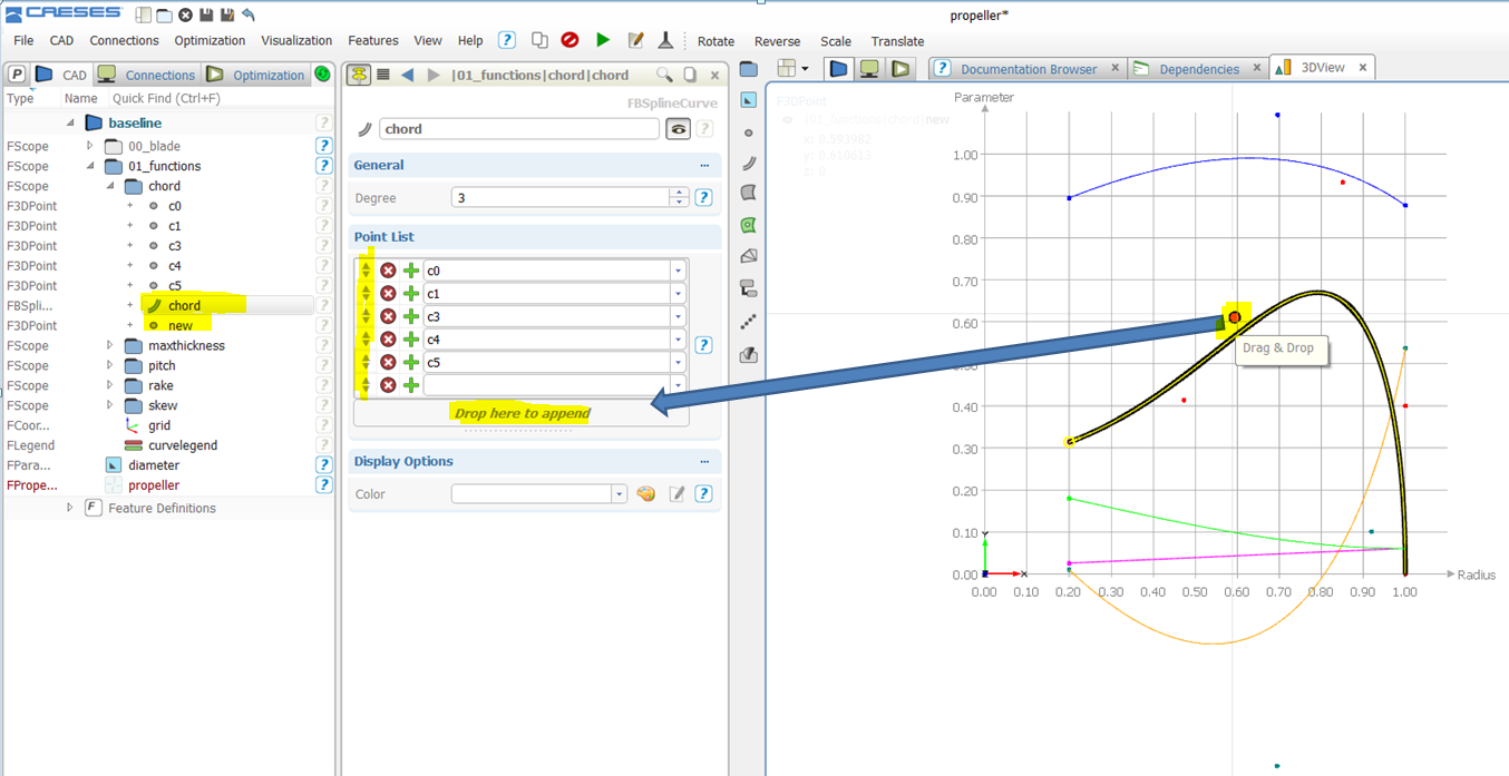
Hi Akhil,
i think they are co ordinates of the propeller chords starting form hub. ie, X and Y
Exactly.
So i tried to add some more chords since there are 10 r/R values and corresponding chord lengths are defined in my propeller.
Good. Simply change the values/add points to adapt it to the table for each function.
But am unable to add any more in the given file. How to do it....?
You could set up a completely new curve or adapt the existing ones. After you added all your points as 3D Points, you could drag and drop it into the pointlist of the respective curve. As it will be added at the end of the point list each time you have to move it manually to its final destination using the arrow buttons.

The other option would be to create all your points, selecting them in the right order and create a new curve via CAD > Curves > e.g. BSplineCurve.
I hope this solves your problems.
Cheers
Matthias
-
Hi folks,
Mr. Akhil Gb posted a very interesting request in the Meta-thread: Marine - Propellers. It deals with the NMRI sample propeller for the famous KCS test case and is maybe interesting for other users of CAESES as well. Please find his post below:
HiAs a part of my research work i am preparing ship model and propeller. KCS ship has been taken for the reference study which is readily available in internet.I am facing some problem with the propeller modelling due to lack of iges or offset files.
I have free licensed software caeses with me. And i observed that there is a 3 meter diameter propeller with NACA66 section is available in the software. I tried to scale down it to my propeller diameter which is 0.105 m with NACA66 profile.But the pitch and other datas are seemed to be different.Is there any way in which i can modify the propeller to my requirement.
Following are the requirement.
r/R P/D Rake Skew(¡£) C/D fo/C to/D0.180 0.834700 0.0000 -4.720 0.231300 0.028448 0.0458500.250 0.891200 0.0000 -6.980 0.261800 0.029641 0.0407100.300 0.926900 0.0000 -7.820 0.280900 0.029477 0.0371200.400 0.978300 0.0000 -7.740 0.313800 0.026769 0.0304700.500 1.007900 0.0000 -5.560 0.340300 0.022010 0.0245900.600 1.013000 0.0000 -1.500 0.357300 0.017324 0.0194700.700 0.996700 0.0000 4.110 0.359000 0.014039 0.0149200.800 0.956600 0.0000 10.480 0.337600 0.011996 0.0107300.900 0.900600 0.0000 17.170 0.279700 0.010440 0.0069300.950 0.868300 0.0000 20.630 0.222500 0.010067 0.0052801.000 0.833100 0.0000 24.180 0.000100 8.700000 0.003690It will be a great help for my future work if you can help me out from these situation with a reference ,tutorial etc.Dear Akhil,
yes, it is possible. The propeller modelling in CAESES is usually based on the generic blade object, which allows you to automatically connect your blade functions (skew, pitch, rake - given in the table above) with a specific profile definition based on a curve engine (with the profile functions chord, thickness, camber - given in the table above) . The result is a single blade with the radius of 1. Please start with having a look into the sample Blade Design > Maritime > Propeller Setup (which you are already refering to) and modify the functions ( baseline > 01_functions) and the blade (baseline > 00_blade > blade) according to the given table data.
Any further step depends on your requirements. If you need a text based output of radial profile cuts along the blade you could try to export the final propeller via File > Export > PFF. If you need a geometry export such as IGES or STL of a full propeller, you would have to take further modelling steps, e.g. using our BREP geometry. Therefore you could have a look into the sample Blade Design > Maritime > Propeller Blade and Hub Fillet.
Please let my know if you have any problems.
Best regards
Matthias
-
Hi Akhil,
very interesting request. I will create a new post here in the general modelling section of our Forum.
Cheers
Matthias
Weights in hydrostatic calculations
in General Modeling
Posted · Report reply
Hi Xavier,
I agree that this is an important step for hydrostatic calculations. Usually, our customers integrate complex hydrostatics by simply connect to specialised software such as Maxsurf or Napa. If you have such software available and you run into trouble with the connection, let me know.
Best Regards
Matthias