


Stefan Harries
-
Content Count
13 -
Joined
-
Last visited
Posts posted by Stefan Harries
-
-
Hi,
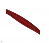
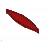
One of the famous hull forms found in literature is the so-called Wigley hull. It is mathematically defined, see attached formula, and used regularly for tests and validation work. By definition the Wigley hull is a (simple) fully parametric model with beam, draft and height as parameters to control the shape (often normalized by length).
A realization of the Wigley hull via a MetaSurface that captures the mathematical formula is given in the attached CAESES project. In addition, some partially parametric modifications are shown, namely, Lackenby type swinging of sections that is realized via a DeltaShift. (Please note that a Generalized Lackenby variation would also be available but was not used here in order to keep the project light.)
If you need the hull for your CFD validation work you can use the various exports for panels, offsets, STL, iges etc.
More information about ship hull design can be found in the marine section of the CAESES website.
Kind regards,
Stefan


-
 1
1
-
-
Hi,
You may have asked yourself why you may actually need a parametric model? In other words: Why does a conventional CAD model not do?
If you are interested in modeling geometry only once, i.e., if you are pretty sure you do not want to change the geometry later, say to adapt to a slightly different design task, well, then it might not be worth the effort to create a parametric model. So, you just produce your geometry in your CAD tool and be done with it. However, if you know that you will have to do variations it should quickly pay off to spend more time up front in order to come up with a model that is somewhat "intelligent."
A parametric model is such a thing: You create relationships between various entities that make up your product. Usually, that leads to a certain hierarchy, i.e., some entities become dependent while others are free to change. The latter are the parameters that you want to vary, for instance within a CFD driven design process. They are often called free variables. A very simple dependency may be that some entities are multiples of others, for example B=0.5*L and H=B*L. Often, the relationship of entities is rather complex.
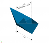
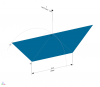
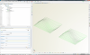
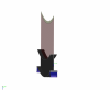
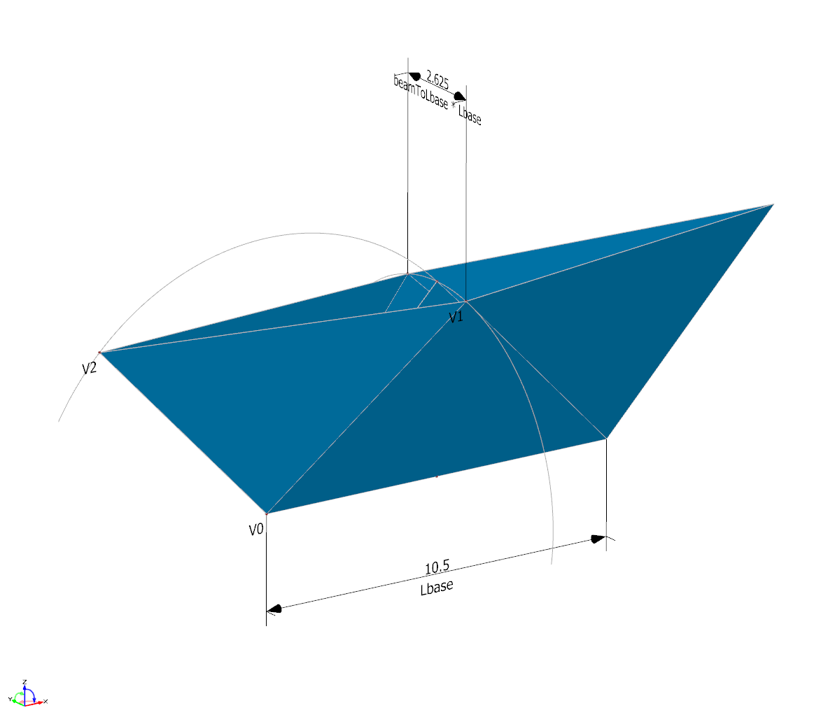
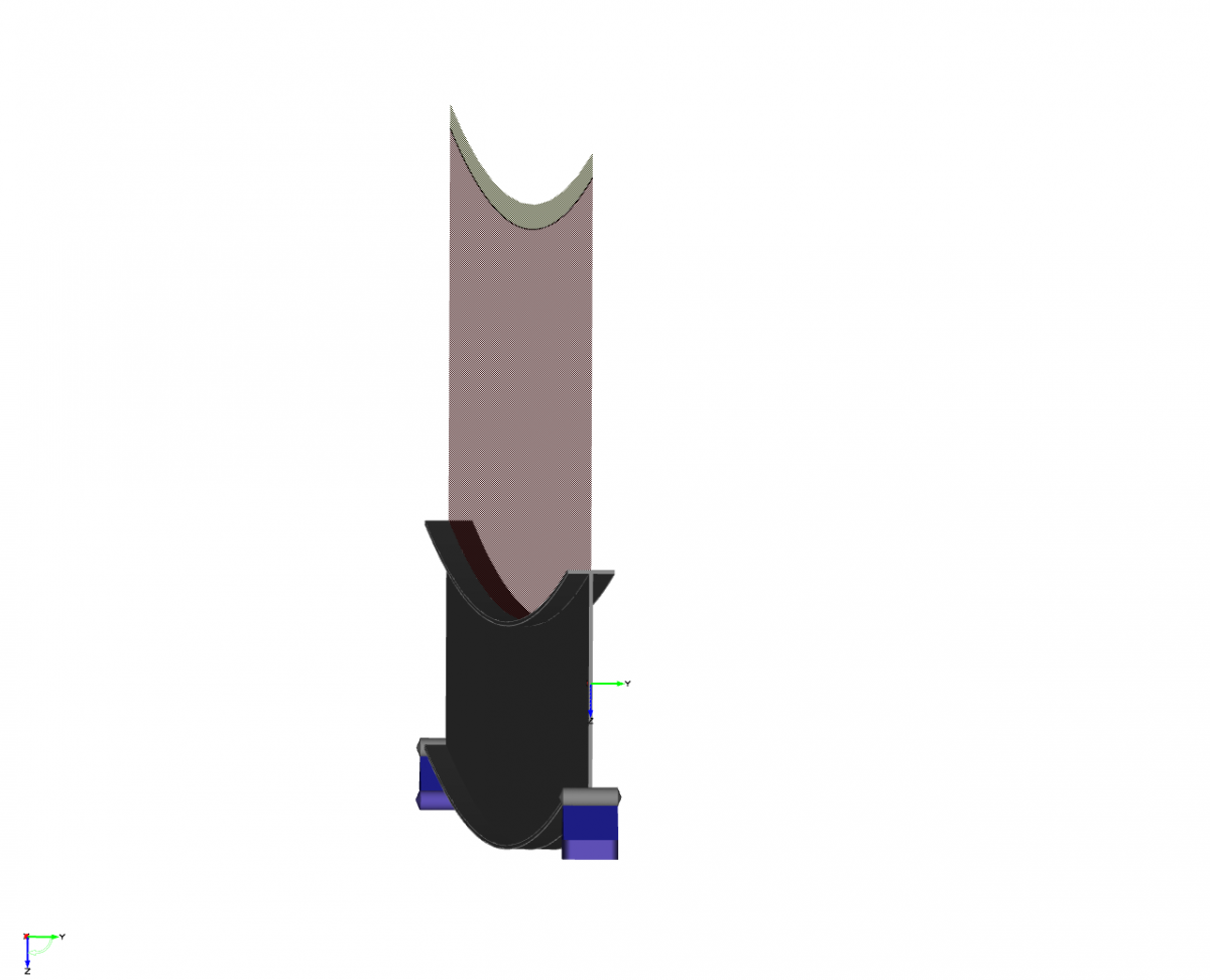
Let us look at a slightly more complicated example (not too complicated though): From a plane sheet of paper you can fold a paper ship. Once you have selected your sheet of paper, for example a standard DIN A4, the size of your ship is set. The only free variable left is the beam of your ship. All vertices of your object are now defined by these two parameters, length and beam. If you do not want to tear your paper apart increasing or decreasing your beam will require your vertices to follow, they are dependent.
Attached you can find a parametric model of such a ship as realized within CAESES / FRIENDSHIP-Framework.
Essentially you get two main advantages from a parametric model:
- You will always get what you want (since you already put in your design rational you will not create anything that is not really of interest at this point in time)
- You will reduce the number of things you have to take care of when making changes (and this reduces the degrees of freedom of your system)
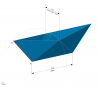
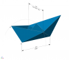
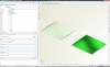
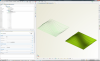
Let us go back to the paper ship for a second: You could still just define all vertices conventionally in a CAD system. Consider the three vertices shown in the example, V0, V1 and V2. They fully define the shape since all other vertices are just mirrored. Together these vertices offer 3*3=9 coordinates for shape control. Taking advantage of symmetry conditions we can boil things down to 2*2=4 coordinates to be modified; V0 does actually not change at all, V1 can only move in the transversal plane y-z and V2 can only slide in the longitudinal plane x-z.
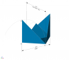
The parametric model intrinsically takes care of this. The knowledge is built in. Consequently, you not only have fewer variables (typically one order of magnitude less) but also no danger of creating something that cannot be produced. In the paper ship model vertex V1 is moved along the circular path in the midship plane. Vertex V2 has to follow such that the distance between V2 and V0 as well as between V2 and V1 is maintained. This defines a circular path, too. Finding the correct corrdinates for V2 is done within an inner optimization (which also illustrates that things can be more complex than just B=0.5*L).
Have fun,
Stefan

-
Hi,
Based on Matthias' example I ran a Design-of-Experiment (DoE) for the exploration of the design space. Here we have just a two-dimensional problem which is nice to illustrate what happens -- would be a bit more difficult in, say, 17 dimensions.
The chosen DoE is a Sobol, i.e., a quasi-random sequence. Nice about the Sobol is that
- you can re-run it and get the same distribution again and again (so, this is good if you need to investigate something that you may have forgotten in the first run),
- you can start with a certain number of variants (e.g. 0 to 99) and then simply add further variants (e.g. 100 to 199, then 200 to 999) which then nicely complement your previous set(s).
To understand how the Sobol works imagine a sunny beach: Early in the morning when the first vistors arrive they will pick a nice spot and put their blankets down. Then the next vistors come. They would choose a spot that is as far away from the first vistors as possible (unless there are other incentives beyond the scope of this technical explanation). A bit later the third group of visitors come and again, for privacy, they would take a spot that is in the region that is still as unoccupied as possible. By the end of the day, assuming nobody can leave the beach, the whole area will be somewhat packed, the last one to arrive always trying to find the region that still gives the largest distance to all neigbors, i.e., filling in the least populated spot.
Naturally, you would rather want a scarcely covered beach. So, the compromise you have to find is a set of variants that is small enough to be quickly computed yet large enough to reasonably understand the design space and to identify regions for subsequent exploitation.
The animations attached illustrate what happens, using the first 10 variants. In real life you do not know the shape of your objective. So, the first animation shows the black-box situation you will usually encounter. The second animation reveals what happens. Naturally, for your actual design task you will most likely never see the shape of your objective(s) since, fristly, you will have more than two free variables and, secondly, you can probably not afford to compute enough variants to get the full picture. (A response surface may help but this is a meta-model which approximates your simulation data which are also just shadows on the wall -- but that is a different story.)
Kind regards,
Stefan
-
Hi,
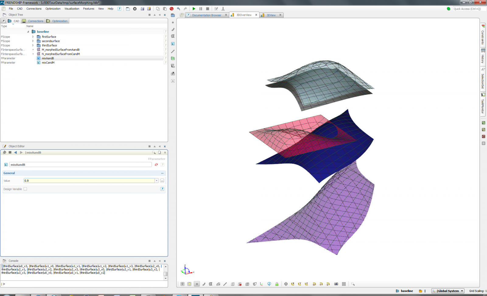
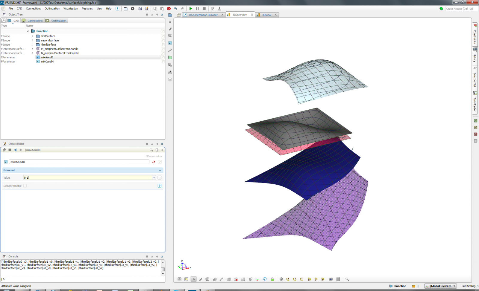
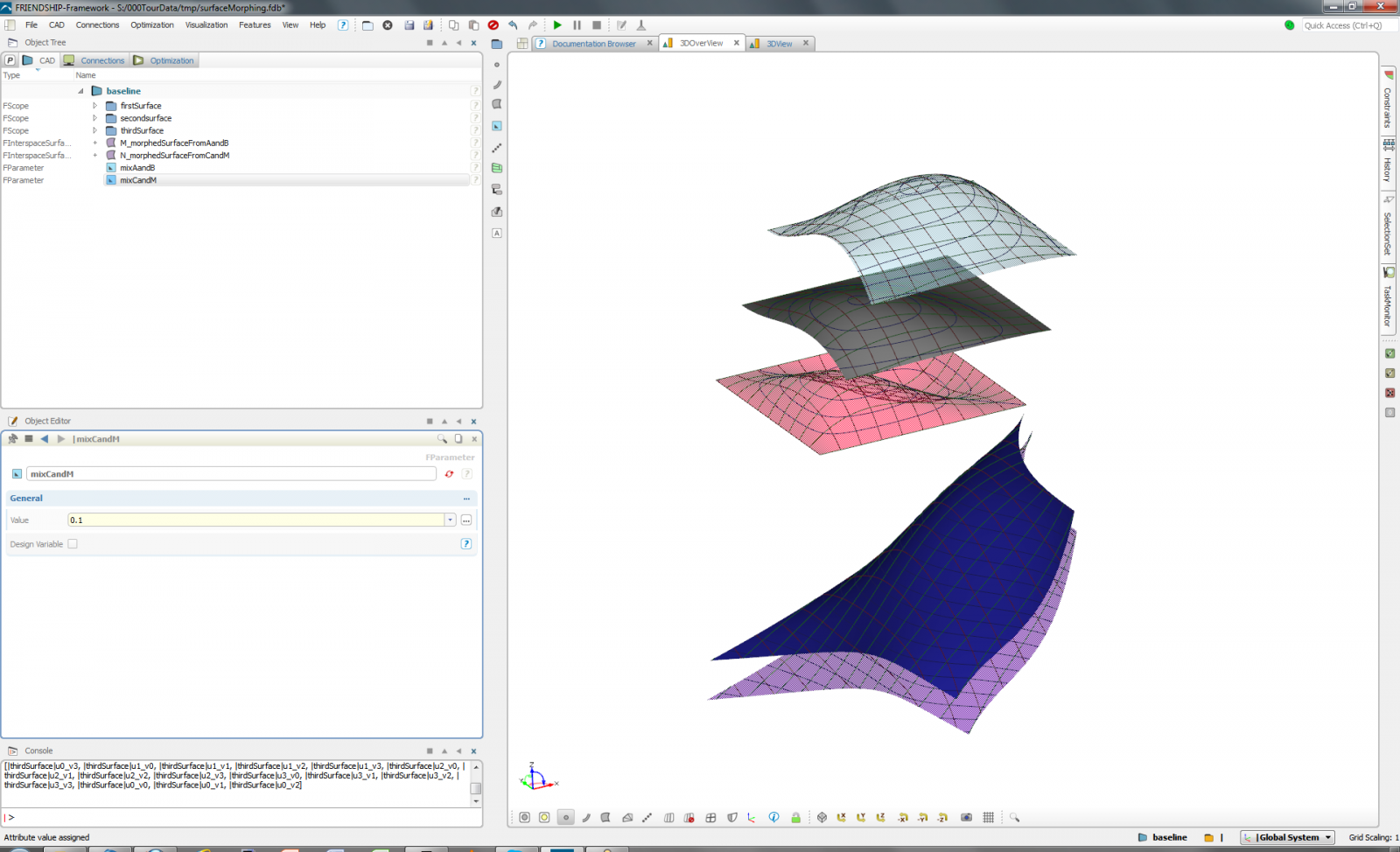
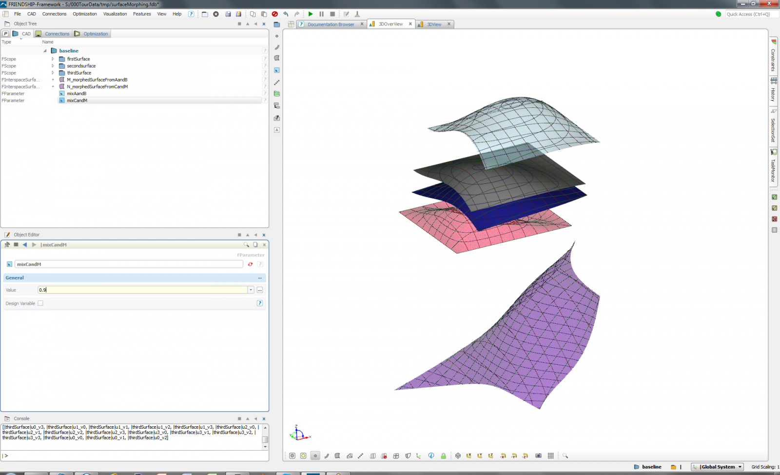
Suppose you have several educated guesses about the possible shape of your product but you are not sure which one of your shapes or which combination of these shapes will be the most suitable for a particular purpose. (Examples from naval architecture: Three different bulbous bows or two different stern configurations -- all look good and reasonable but what is the best mix?)
One way to set up a parametric model (a partially parametric model to be more specific) is to use morphing, i.e., the smooth transition from one object to another by weighting. Suppose you have a cat and a dog. They look reasonably alike (two ears, two eyes, one snout etc.), meaning their topology is the same even though their geometry differ. If you set your weight to 100% cat and 0% dog, well, you get the cat. If you do it the other way round you would have the dog. Anything in-between, say 60% cat and 40% dog, makes an interesting mix, a cat-dog so to say. (No way to produce a donkey, not even by extrapolation.)
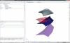
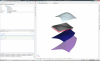
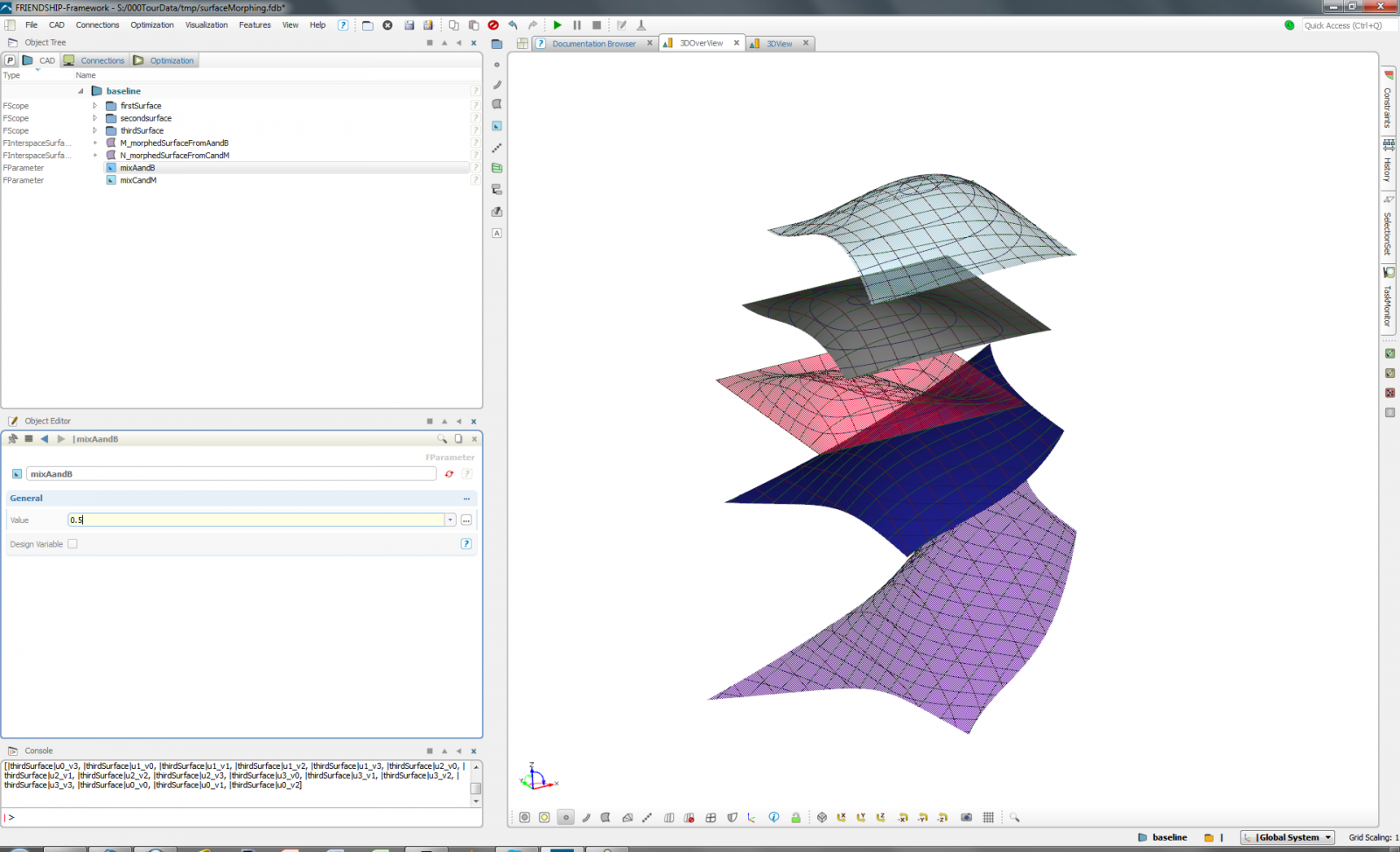
Within CAESES / FRIENDSHIP-Framework you can build on this idea by utilizing one or several interspaceSurfaces. Assuming you have the same topology for your surfaces (matching orders and matching numbers of vertices when it comes to B-splines), you can interpolate between your shapes. Attached please find an example in which several surfaces are morphed.
Cheers,
Stefan


-
1
-
-
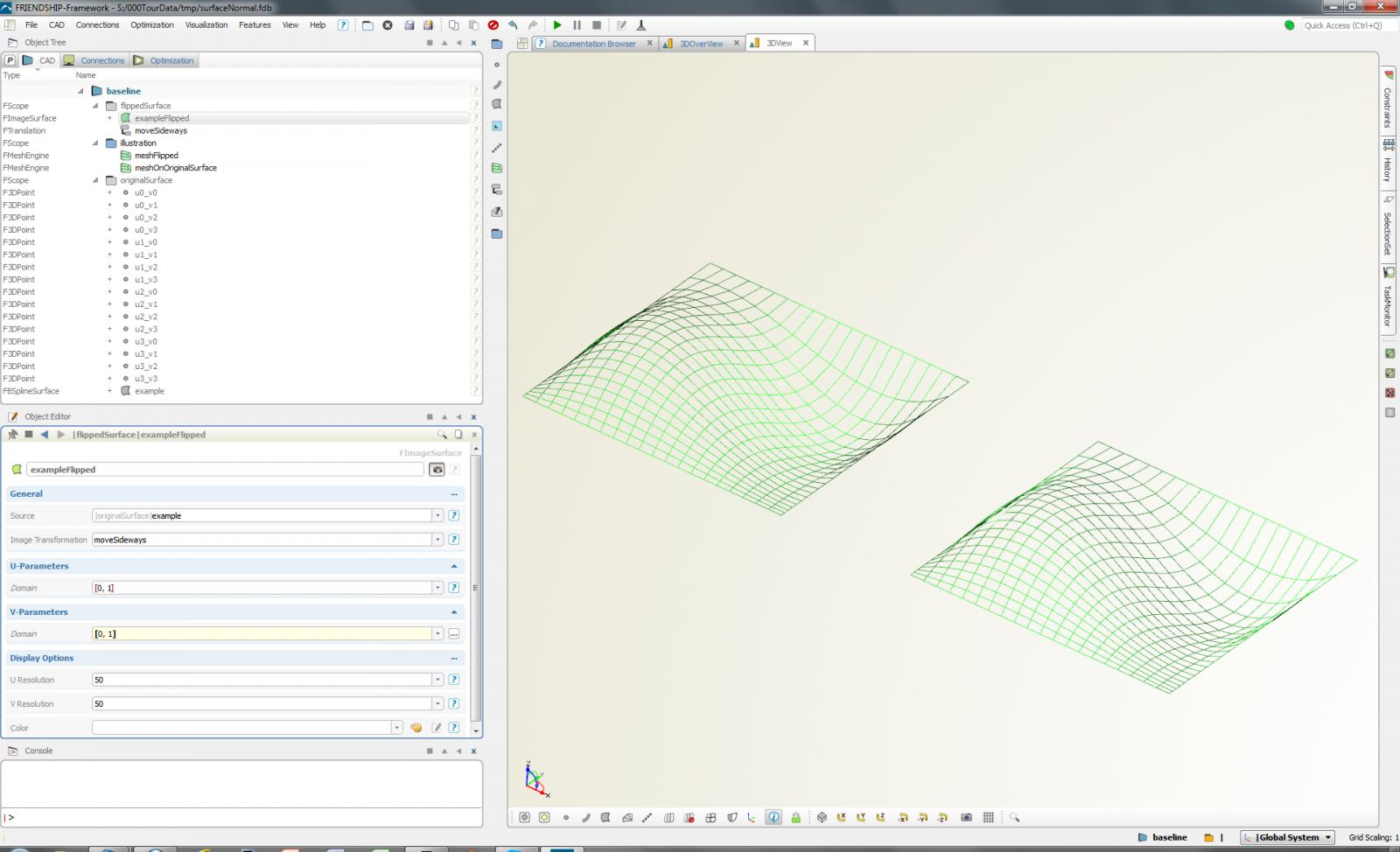
Hi folks,
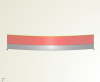
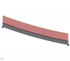
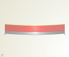
Further to Mattia's and Claus' entry I would like to add a small example. It contains one simple B-spline surface and an image of it. The image is translated sideways in order to show both the source and the image in the same figure.
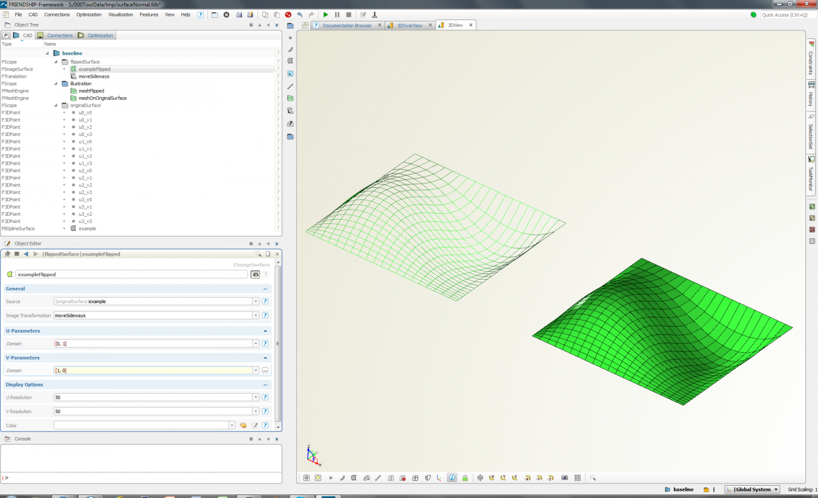
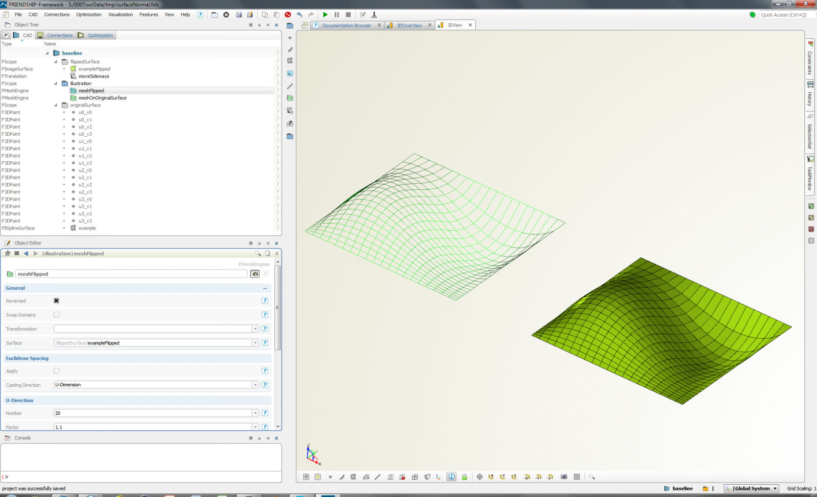
When both the U-Parameters and V-Parameters run within the interval [0, 1] the surface normals point into the same directions. However, reversing the V-Parameters of the image to [1, 0] flips the surface normals. To illustrate this a meshEngine was utilized on the two surfaces. (Within a meshEngine the normal direction is indicated by transparency in one and opaqueness into the other direction. Note that you can also change the normal direction within the meshEngine itself by selecting the Reversed option.)
Kind regards,
Stefan
P.S. You may want to check what happens when you change the U-Parameters from [0, 1] to [1, 0] and set the V-Parameters to [0, 1]. What does this do to your meshEngine (which I deliberately set up as an asymmetric mesh)?
-
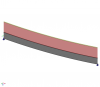
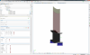
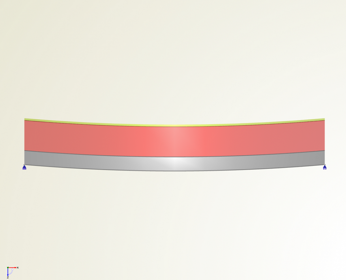
Further to the DoE I ran a T-Search and got a bit less weight, namely 0.627 t for B=0.1198 m, H=0.5791 m and thick=0.01 m, see figure attached.
Cheers,
Stefan
-
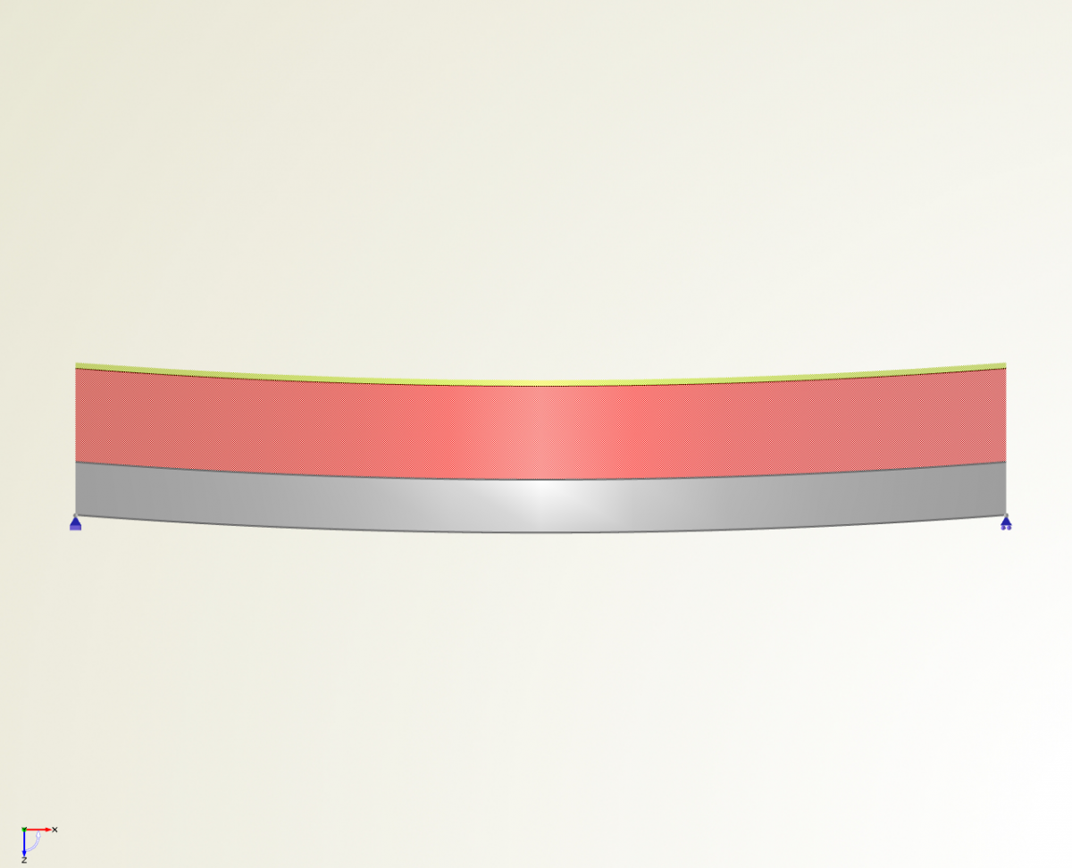
Hi,
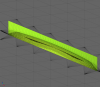
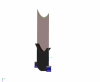
In case you want to play with optimization strategies without the need to couple CAESES / FRIENDSHIP-Framework to any outside simulation code, you may want to use a simple example of a beam in bending. It uses beam theory for an I-beam, visualizing geometry, payload and weight.
Just get started with the project file and a pdf with some explanations.
A first DoE for a 10m beam with a payload of 10t yields 0.651 t for B=0.1813 m, H=0.4797 m and thick=0.0109 m. Maybe you will find something lighter that still fulfills all constraints?
Kind regards,
Stefan
-
Geometric modeling techniques in Computer Aided Design (CAD) can be classified in many different ways (boundary representation vs. constructive solid geometry, discrete vs. transfinite data, regular vs. irregular topology etc.). One classification distinguishes the way shapes are produced and varied:
- Conventional modeling:
Shapes are defined by data items that are independent of each other and do not bear any task specific information. The polyhedron of vertices that define a B-spline surface is a good example for this.
- Partially parametric modeling:
Changes to the geometry are defined by means of parameters, i.e., a set of modifiers associated with the design task at hand, while the original geometry is utilized as-is (and may come from any suitable modeling process). Morphing is a well-known example.
- Fully parametric modeling:
The entire geometry is defined by parameters, i.e., task specific descriptors which capture the essence of the product to be generated or varied.
Ideally, the functionality of your CAD systems allows you to flexibly combine these techniques, essentially leading to a hybrid approach. This is the case with CAESES/FFW.
- Conventional modeling:
-
Hello there,
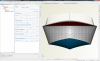
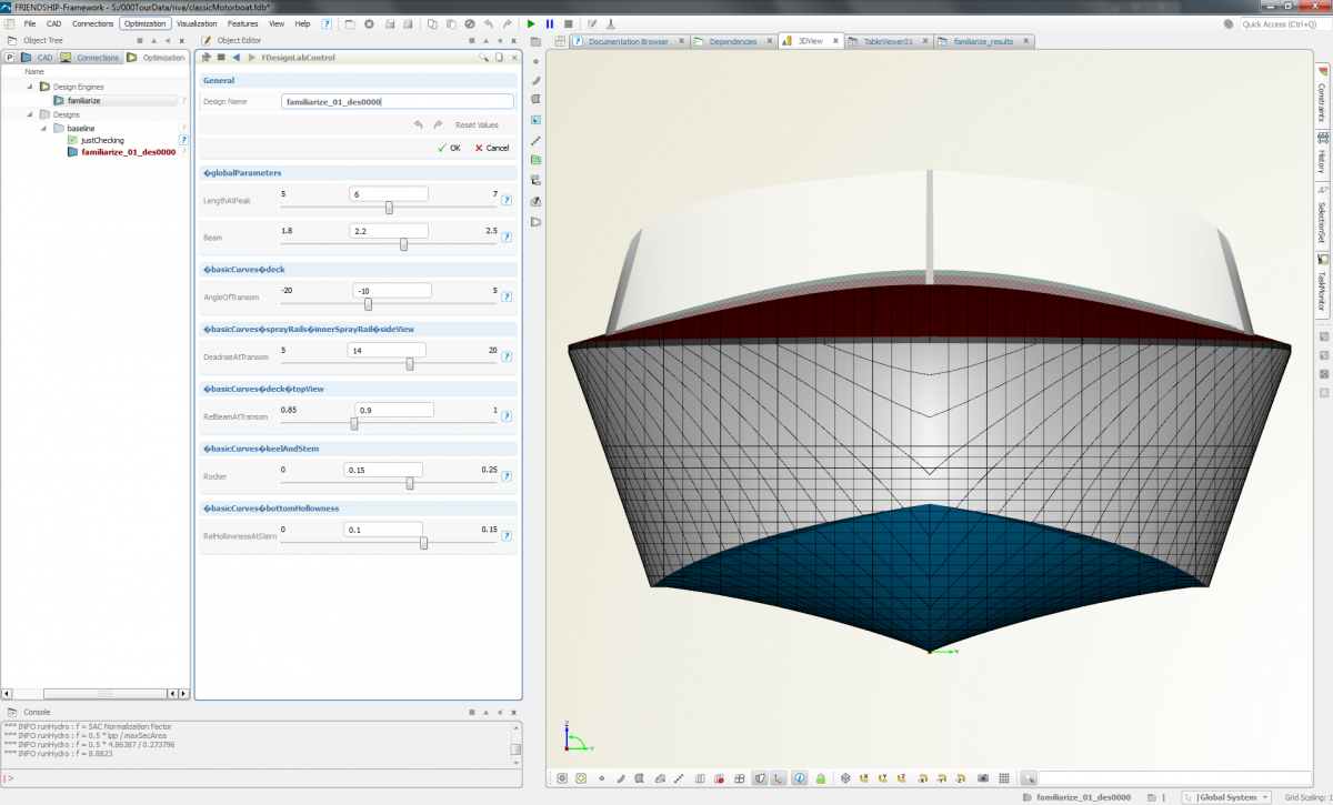
In case you have ever seen (or driven) a wooden motorboat built in the sixties and seventies, you may have been hooked by their classic beauty.
If you are interested in doing some "remodeling" please use the fully parametric model that I created some time ago. (It might not qualify as a very close replica but it should help to understand the ideas behind parametric models for functional surfaces.) In order to play with some of the parameters please go to the DesignLab called "familiarize" (see Optimization tab), create a design and modify some of the free variables.
Kind regards,
Stefan
P.S. Naturally, if you want to share similar models, please do so -- it will be much appreciated!
-
As time goes by...
In case you are wondering why your time is not flying: You have to select the object "timer" and start it (e.g. right mouse click and "Start").
Cheers,
Stefan


Utilize CAESES / FRIENDSHIP-Framework to read off data from diagrams
in Miscellaneous
Posted · Report reply
Hi,
Sometimes diagrams with important data are available only as graphics files (e.g. after scanning from a report or upon exporting from a pdf-file). CAESES / FRIENDSHIP-Framework can be quickly utilized to read off data from diagrams with high accuracy.
To do so, import the graphics as an png-file within a "GL Picture Frame" (1st step). Upon setting the scales of abscissa (x-axis) and ordinate (y-axis) (2nd step) you can readily position a point in your diagram and get your x- and y-coordinates (3rd step). (You may want to use such a point to check the level of accuracy.) Furthermore, you can approximate a graph with a curve, say a B-spline curve (4th step) or interpolate it (5th step). Using the curve representation you can "inquire" the y-value for any given x-value (6th step).
The attached fdb-project illustrates the work flow for an imaginary speed-power curve.
In addition to using CAESES / FRIENDSHIP-Framework to extract data points from diagrams, you can follow the same approach to replicate a lines plan of a boat, yacht or ship, circumventing classic digitization. Offset data are thus produced effectively. Nice side effect is that you can adjust selected points, for instance to improve accuracy of lines remodeling and "repair" apparent outliers.
Kind regards,
Stefan
ExampleDiagram.zip