

Ben Zeitz
-
Content Count
19 -
Joined
-
Last visited
Posts posted by Ben Zeitz
-
-
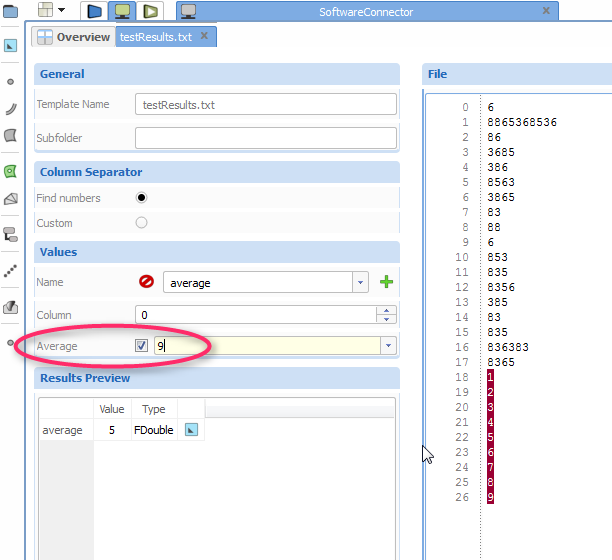
You can also get the average of the last n rows from the result file editor. See screenshot.

-
Dear Ken,
Sorry for the inconvenience. This bug will be fixed in the next release of CAESES.
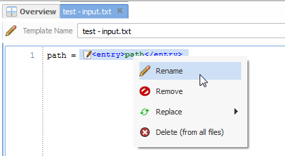
As a quick workaround you can also rename entries directly in the template editor by just clicking on them (see screenshot). If you do it this way it won't crash.
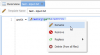
Ben
-
Hi Johannes,
Usually you don't need to care about paths in CAESES.
CAESES automatically executes the integrated software (StarCCM+ in your case) in a certain result folder and that is where the software expects all input files to resist and where it then stores the results files. So you just have to deal with file names, not with the paths.
Result files (as well as input files which need to be manipulated for each run) are handled as "templates" in CAESES. Have you checked the tutorial "External Software" yet? The document explains nicely how the parts of a software connection work and how to set them up. You find it in the Documentation Browser of CAESES: Tutorials/Getting Started/External Software
I would suggest:
- Remove the path of the stl file which is hard coded in your java script file. Just leave the file name there. (If necessary you can also add a relative path, e.g /subdir/filename.ext)
- Do the same for the result file(s).
- Add all needed input (stl, js) and output (results) files to your Software Connector.
- Set the executable (StarCCM+) in the Computation of the Software Connector.
- Set up a value which should be read from the result file and create a parameter with this value. You can do that in the results template you have just added to the Software Connector.
- Use the parameter as evaluation in the Sobol design engine.
- Now run the Sobol design engine.
The parameter then tries to extract its value from the (yet not existing) result file which triggers StarCCM to run and produce that very file.
Cheers
Ben
-
Hi Edan,
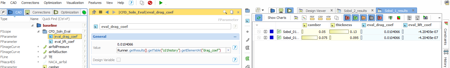
The name of file used in the parameter expression can be both "cd-1-history" or "cd1history". Both ways will be parsed properly. Please see attached screenshot (Of course my example is stupid, because I just copied some fake result files. Pointwise and Fluent weren't really executed. The little test should just prove that the process generally works.)
My assumption would be that the result files do not exist when CAESES tries to read them. Maybe Pointwise/Fluent have terminated without creating the files?
Please check the console output. Is there an error message which says that CAESES could not open a file? Something like:
"*** INFO FGenIntReader : Could not open file .../NACA4DS_Connection_Test/manual_results/baseline/Runner//cl-1-history for reading [parsing process aborted]
If you find such a message the file most likely does not exist (or has a different name) and therefore the parameter cannot be updated.
Cheers
Ben

-
Hi Josip,
No sorry, this is not possible the way you suggest.
You cannot create references from one entry to another in a configuration or directly in an input file.
Instead you can create all references you need outside of the configuration.
1. If you like to work with a series you could create a Series Parameter and set the desired double values to it.
In your configuration you have to create entries for each value you like to get written into the input file.
To access the values of the series set an expression like this to your entries: mySeriesParamter.getValue().at(0)
2. If you like to get one entry initialized with the value of another entry you simply can set the same expression to both of them.
e.g.
myParameterX = 1.5
entry1 = myParameterX
entry2 = myParameterX + 0.5
So, you still need to create a parameter for each value you like to use as an expression. The advantage of this approach is that you can work with references even between different configurations.
Cheers
Ben
-
Hello Britton,
To me it looks like one or more files of your tools were not found which interrupts the process chain.
... in the software connector I used the Input file selector to select the file from the RAGOO output. I then edited it because the filename will change based on the design name as follows:Ragoo.getResults().getResultFileName(4_RagooPrep|43_RagooInputParam|ModelID + "_01.vin")
You should rather make the name of the RAGOO output file dynamic than the name of the input file of the next Software Connector in line.
How about creating a string parameter and set it as name of the RAGOO ouput file. The string parameter can get an expression set as value, so both the name of the RAGOO output file and the name of the input file for WinDESIGN change dynamically to what the string parameter evaluates to.
I have attached a very small and simple project which hopefully makes my suggestion more clearly.
[This tool could generate a lot of these vin files ... is there anyway to grab all of the *.vin files for input in the next directory?]No sorry, this is not possible yet. One file corresponds to one item (input or output) of the Software Connector. There is no item for multiple files.
Not a bad idea though. Perhaps we provide such functionality in the future.
Best regards
Ben
-
Hi Kristina,
I guess we will find a solution for your task.
1. It should be possible to import the airfoils by creating a feature. The feature should get the file as an argument, open it, read-in each line and extract the point data from it (that depends on the format the file is written in). With the point data the feature could for instance create FBSplineCurves were the points are set as source.
Please have a look at the feature definition of Features/hull design/connections/neptune/Import SRI Offset File
This feature shows how a file can be read in. Please notice line 20-22 of the feature definition. There are some double values extracted from a read-in line.
Another helpful feature could be Features/curves/nurbs/Planar B-Spline Curve
This feature creates a FBSplineCurve by creating a bunch of F3DPoints and set them as source of the curve.
2. The distances X4, X5, X6 and X7 need to be set to some discrete values, right?
You can set-up a number of discrete values for each design variable. E.g. a variable can be 10, 11.5, 13, 17, but nothing else. Now, if you use this design variable in a Sobol it will iterate over the configured possible values only.
Please click onto the three dots symbol (…) in the upper right of the “General” headline when a parameter is selected. This expands the “Possible Values” option. (Hint: Just click on the name “Possible Values” to make the option always visible.)
I hope that I have understood your questions correctly. Don't hesitate to post here if you need further assistance.
Good luck!
Ben
-
Hi Tanzil,
Yes, I guess that should be possible.
You still should use the software connector, though.
Set up an input template as you described above up to the part where the geometry begins. Replace all needed values with so called entries (the GUI should automatically offer entries for numbers in the template, just chose the wished ones). Then set the proper designVariables (the ones you use in the sobol) as values of the entries.
Now half of the needed input file is ready.
The geometry file is generated by an extern application, right?
How about creating a small batch file which merges the input template and the geometry file into one input file for your evac-code? (Assuming it is easy to merge, the geometry just written straight after the other input values.)
After merging process the batch file has to execute the evac-code with the new created input file.
Then set the batch file as application in the computation of the software connector.
That's all, run the computation to see if it works. I hope that will do the trick?
Another approach could be to create the input file entirely in a feature. (Just create the file, there still seems to be no reason to run the sobol in the feature.)
That would shift the task from batch-programming to feature-programming.
Here's an example of my colleague on how to do it:
Good luck!
Ben
-
Hi Tanzil,
I wonder why you want to run the the sobol from within a feature?
As far as I can see you could accomplish it more easily by just setting up a template in the software connector.
Or do I miss something?
See Documentation Browser -> Tutorials -> External Software in CAESES for a step by step tutorial on how to set up a software connector.
(Additionally I attached the tutorial here)
Cheers,
Ben
-
Hi Shahriar,
Have you checked the samples and tutorials which are shipped with CAESES yet?
Please open the Documentation Browser and move to tab "Tutorials". In section "Getting Started" is a good explanation of how to couple codes with CAESES. Name of the tutorial is "External Software".
There are also some samples which demonstrate the coupling of external software and CAESES. Please see section "Integration" of the samples tab.
I hope the tutorial(s) will give you an idea of how it works in general.
But of course, every optimization task is different, so don't hesitate if you have further questions.
Cheers
Ben
-
Hi Jurgen,
And welcome to the CAESES community!
It's a nice hobby you got there! :)
I'm afraid I didn't exactly understand your question.
Anyway, as a general hint I would advice you to check out the samples and tutorials we ship with CAESES. You will find them in the Documentation Browser located in the central widget of CAESES.
Additionally there are a couple of videos which might are of interest to you. You can find them here:
http://www.youtube.com/user/FRIENDSHIPSYSTEMS/videos
Cheers
Ben
-
Hi Toni,
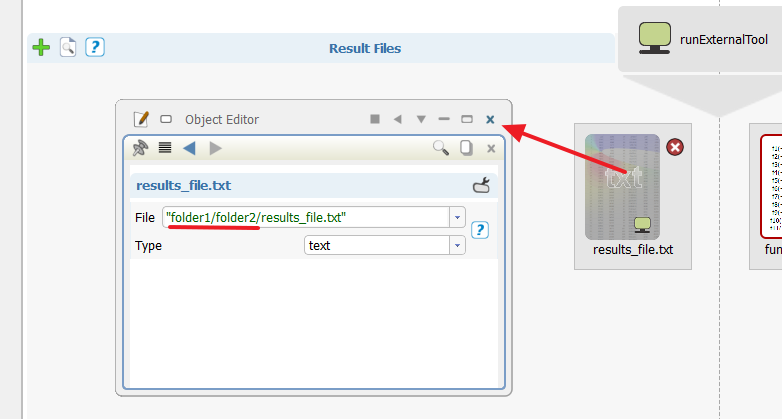
You can simply write the sub-path before the file name.
I guess this screenshot explains better what I mean:
So, if there is just the name of the file it has to exist in the folder of the computation (The folder which has the same name as the computation).
From there you can go deeper into a sub folder structure.
Cheers
Ben
-
Hi,
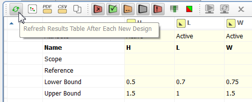
Just a little reminder on how to speed up an optimization run if it comes to many designs (>500).
Unset the "Refresh Results Table" button in the leftmost position of the tool bar of a Design Results Table (see pic).
It will prevent the table from updating after each new design. (By the way, this is a global setting and works for all Design Results Tables.)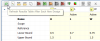
Because all statistics and bars have to be re-calculated and the entire table has to be re-drawn whenever a design is added to the table it consumes a certain amount of time to do this for many designs. In addition the update process takes longer the more designs the table contains.
If the "Refresh Results Table" button is unset the table updates only once after the run has finished.
But of course, you can always toggle the "Refresh Results Table" button while the optimization is running to refresh the table manually.
Cheers
Ben -
Hi Humberto,
Actually it is a little complicated to re-use an already set-up software connection.
We are working on a smarter solution which do the job in a mouse click, but for now you have to perform the following operations:
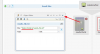
1. Export the wanted definition by right-click onto it in the object tree and chose "Save Definition" from the context menu.
The definition stores all necessary information of a software connection, e.g. all set-up input and output files.
You find all definitions in the leftmost tab of the object tree. The one with the "P" symbol on it.
2. Import the definition in a new project by typing "importGenIntDefinition()" into the console.
3. Create a new software connector.
4. Connect the imported definition with the new software connector by setting it to the configuration of the software connector.
You find the configuration in the "Connections" tab of the object tree.
Select the configuration and expand the "General" section by clicking on the little three-dots symbol (...).
Now select the imported definition.
5. The software connector will be reinitialized with the imported definition.
6. If you want to clean up your project you can delete the no longer needed definition which was created with the software connector and formerly set to the configuration.
Cheers
Ben
-
Hi Stephane,
We ship a sample of an OpenFOAM integration with CAESES.
Please see Documentation Browser -> Samples -> Integrations -> OpenFOAM Setup Ahmed Body
You might also like to have a look into the shipped tutorials to get an idea of how post-processing, modelling tasks and things like that can be done with CAESES.
Cheers
Ben
-
 1
1
-
-
Hi Claus,
Yes, i'm afraid it would be difficult.
Like i said, the Design Result Table is very specialized. It has an underlying structure model consisting of designs, designVariables, evaluations and constraints. All these things are carefully connected to a caching system (not to mention result states, statistics, optimization run belonging and stuff like that...). A simple file of rows and columns just doesn't fit into that structure. I wouldn't advise try bending everything that much to make such an import possible.
If needed i guess it would be easier to implement automatic report generation (like PDF files) for the common result tables.
Cheers
Ben
-
Hi Erik,
Well, you could trick CAESES to read in your data as a result from a fake computation.
- Create a Software Connector and set a dummy file (just anything) as local application for the computation.
- Then let it run. Of course nothing will happen due to the set dummy executable, but the proper folder structure will be created by CAESES.
- Place your data file in the just created result directory (Something like: .../workingDir/projectName/manual_results/baseline/computationName/)
- Then create a new result file in the result files area of the software connector and select your data file from the open file dialog. Don't forget to check if the type of the file is set to "generic table" (see Object Editor).
- Now you can run the computation again or "read in existing result files" (right click on computation item).
You will then get a table with all the values from the data file.
But of course, that works only if the data can be read in as a table, e.g. comma separated numbers or such.
If we are talking about the so called Design Results Table here it is simply not possible to load a single file into it. That is because the Design Results Table is too specialized. It shows designs from an optimization run and extracted values of the results of these designs.
Cheers
Ben -
Hi Leo,
Yes of course, it is possible to connect your tools to CAESES.
The most easiest way would probably be to use the Software Connector of CAESES.
Have you already checked out the shipped samples and tutorials? (see tutorials tab in the Document Browser)
I'd like to draw your attention to the tutorials "Geometry Variation" and "External Software". They should give you a good idea of what can be accomplished with the Software Connector and how it is done.
Best regards
Ben
Batch Mode
in General Modeling
Posted · Report reply
Dear Emre,
please use CAESES_crt executable in order to start CAESES in batch mode.
Kind regards
Ben