


Mr. Daehwan Park
-
Content Count
67 -
Joined
-
Last visited
Posts posted by Mr. Daehwan Park
-
-
Hi Hasan
I tried some trimeshes to be exported as a STL file.
In the project I added a folder for this work "z_Trimesh_dp"
01 _additional_surface >> Deck and Transom surfaces are added.
02_trimesh >> 3 trimeshes are created, port, stbd and watertight.
In the objectEditor of 'watertight' you can find Info > #Open Edges = 0, which means there this trimesh is watertight.
Just try exporting it as a starCCMSTL and test in STARCCM+.
https://fcloud.friendship-systems.de/index.php/s/23W24ieNxtSLaJM
Cheers
Daehwan
-
Best one, in my opinion, is stlSTARCCMSTL.
Surface problem could be handled with Trimesh skill to produce watertight triangulized surface mesh.
If Ok you could send me the surface file through emal park@friendship-systems.com.
Best regards
Daehwan
-
Hi Eloise
The procedure to get a section area is like below :
1. Create a SectionGroup at one x position from trimesh, surfaces or brep.
2. Convert the SectionGroup to OffsetGroup.
3. Extract an offset
4. Create a BSplinecurve from the offset
5. Cut the curve at draft (using ImageCurve manipulation.)
6. Get the areas from lower curve and upper curve.
All steps are introduced in the FDB you could download from the link :
As Claus said, I also recommend to use HelpDesk for any questions.
Cheers
Daehwan -
Hi Daphne
1. Create a new trimesh and insert all green imageTrimeshes in the new one.
2. Select the new trimesh
3. Go to menu bar and select File > Export > STL
I am not sure this is what you really want but this is a most general way to export trimeshes.
Cheers
Daehwan -
Hi Daphne
It seems that you are doing very well and soon the LackenbyShift will work successfully.
The ImageSurface "NewHull" can have a surface as its source.
In this case, please create another Brep with a certain name to distinguish it as a final hullform for example "FinalHull".
And in the Transformation slot in the FinalHull insert the LackenbyShift. Then you will see the shape will be transformed by LackenbyShift.
Have a nice weekend!
// Daehwan
-
Hi Daphne
I guess your model would be scaled by its length and the origin is set in the middle.
You need to change the position values suitable to the model.
// Daehwan
-
Hi Daphne
NurbsSurface or BSplineSurface does not work for assembling several surfaces.
There is a data type SurfaceGroup that works for it. But the SurfaceGroup cannot assemble Surfaces and BrepParts together. In this CASE Brep is the alternative since Brep can assemble Surface and BrepParts in one Brep object.
1. Assemble the surfaces and brepParts in a Brep.
2. Create a SectionGroup with the Brep.
3. Create a Hydrostatic Calculation
4. Create a LackenbyShift using the SAC from the hydrostatics
5. Create another Brep in the same way with 1.
6. Insert LackenbyShift in the new Brep.
This is the proceedure that you want to make.
//Daehwan
-
Hi Daphne
I guess the OVERLAP is just a matter of visual effect.
When you delete an original brepPart, then the Brep will also lose the same source.
Just click the scope having the original brepParts and surfaces to shut off. Then the color of the scope will be changed to gray and all the geometry under the scope will be unvisible.
// Daehwan
-
Hi Daphne
1. Select all surface patches and brepParts.
2. During stil selected, create a new brep.
Then they are assembled in a one brep.
// Daehwan
-
Hi Daphne
I guess you might have imported iges.
All segmental patches of Nurbssurface and FBrepPart should be assembled in one Brep. Then the Brep can be used in Hydrostatic proceedure and all shift variations including lackenbyShift.
Cheers
Daehwan -
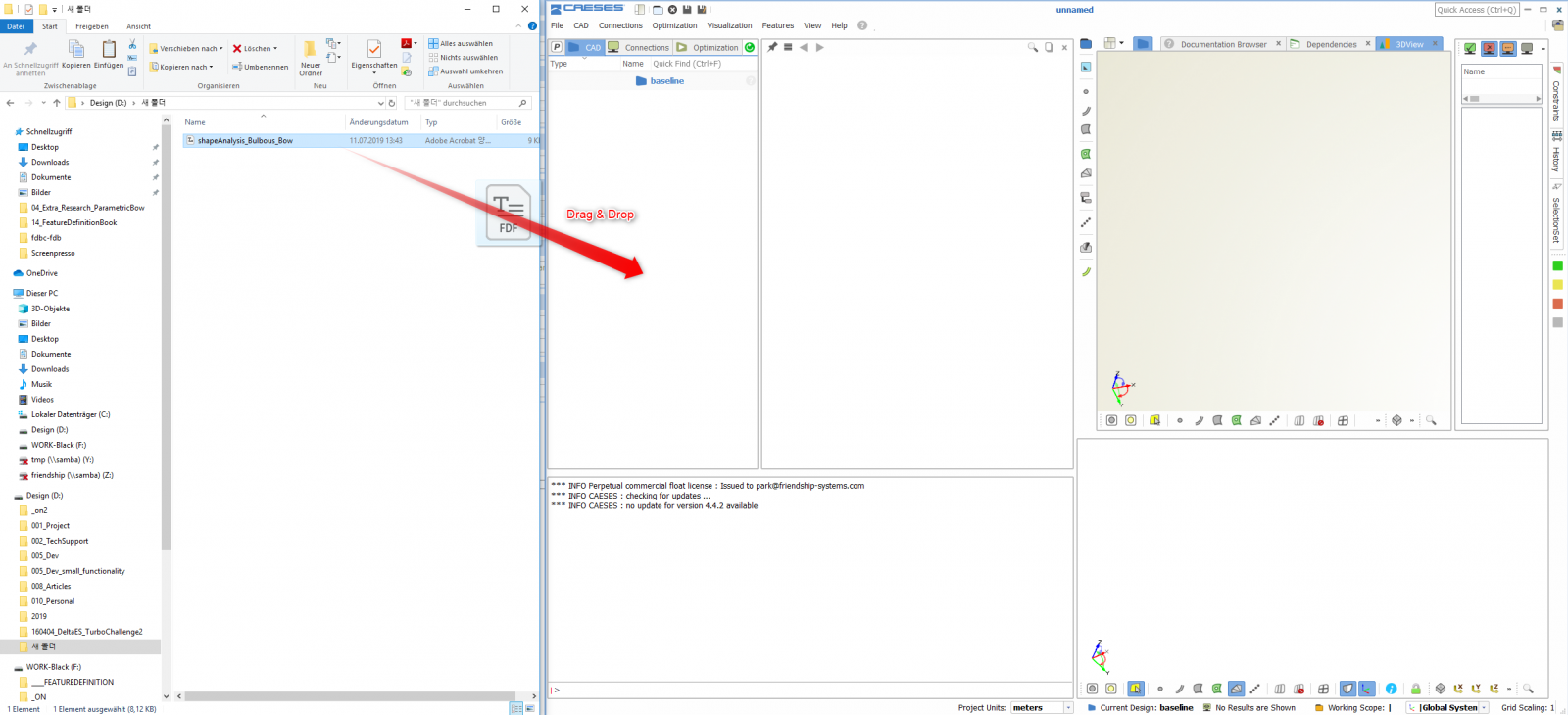
Hi Daphne
There are several ways to import the fdf file but here I would like to introduce you the easiest one.
Just drag and drop.
Cheers,
Daehwan
-
Hi Daphne,
Could you explain your situation detailed a little bit more?
Which fdf of yours and where is it saved now ?
//Daehwan
-
Dear Daphne
The form variation shown in the attached thumbnails above was done from a fully parametric model. In order to get step by step idea for hull form creation in parametric way you could get information from the tutorials embeded in CAESES. Please go to Documentation Browser > Tutorials > Hull Design.
For bulbous bow modeling, it would be good to refer the article below.
https://www.caeses.com/forum/index.php?/topic/315-bulbous-bow-shape-analysis/
Best regards
Daehwan -
Hi Alex,
It is so sorry to say that we in Potsdam have no experience to connect shipX with CAESES. But, as you know, any software can be integrated in CAESES just if it can be run in batch mode. I am also looking forward to any advise from someone who knows Waveres well.
Best regards
Daehwan -
Hi Priyanka,
I seems that IGES file is missed.
Anyhow, I think it would be appropriate to apply Lackenby variation for new variants keeping displacement same.
Cheers
Daehwan -
Hi Priyanka
Could we share the excel file ?
Cheers
Daehwan -
Hi Prachi,
Since offset or offsetgroup data are static values, when we change the values in copyOfGroup(originalGroup) then the values in originalGroup(offsets) are to be changed, too.
Usually I follow a mechanism utilizing imageOffsetGroup to copy an offsetGroup and edit it freely out of the original offsetGroup.
OffsetGroup OG(offsets)
Imageoffsetgroup IG(OG)
OffsetGroup CG(IG)
Like this way the copied offset group can be editted freely out of original offset group. I hope you could get a helpful idea from this.
When you provide me your FDB file, then I think I would try setting it up for your purpose.
Cheers
Daehwan
-
Hi Priyanka,
In which format do you have offset data ?
And how do you like to evaluate "the best hullform", for example, do you use a specific CFD?
Cheers
Daehwan -
Hi Sumit,
1. Sobol + Tsearch
In the case the user wants to learn the design space, 'Sobol' could be the first option. Sobol does not have approaching mechanism toward minimum or maximum but distributes the values of design variables most fairly. User could have a good perspective that how much each of design variable influences to objective. Selecting the most effective design variables, user can reduce the number of design variables and therefore the computation time.
Practically the best design from Sobol could be chosen as a final result if it is agreed among the design participants. When user wants to go further for searching minimum point, TSearch can starts from the point of Sobol to find out smaller point.
2. Response surface method (RSM) from Dakota
When user does not need to learn design space and has to start optimization directly, Dakota RSM would be a good option to choose. RSM approaches quickly to minimum point avoiding folling down in a local minimum. Tsearch could be an option but it imposes always the possibility to fall in the local minimum point.
Best regards
Daehwan -
Hi Yanxin,
I have seen such a view when the coordinate values of the geometry are too large. I don't how much it is in your model but I think it would be worth to check it once.
-
Well, I don't know well but I think you Need to check first if the Offset Group was created correctly.......... and try to enlarge grid size from vcoa to a larger.
And please Keep in mind that Flowtech People can help you much better :).
Daehwan
-
Hi Iorga
I am not an advanced user of SHIPFLOW but I think there we Need some corrections in the command file.
Xflow
- hull : Add "Vof"
- hull : Erase higr, ogrp, fbgr and abgr
I am not sure this will solve the Problem but hope it would be worthy to try.
If not solved, this issue should be managed by FLOWTECH Support including Tecplot error.
Hope this could be help.
Daehwan
-
Dear Mr Kang
Thank you very much for itroducing your practical idea to construct hybrid parametric hullform Generation structure with CAESES.
Before getting into the technical Focus suggested by you, I think it would be valuable for us to discuss about the issue of
Direct form Variation with DMP file.
In between except our summer vacation days he tried developing a new work flow of Import-vary-Export a DMP file directly.
We have a Progress but we could not have Chance to test it since we don't have Tribon System here.
My suggestion on this Topic is that we try first the direct dmp process even though it is not perfectly finished yet.
If you agree with the direct dmp process then I am going to start cooperate you in that way immediately.
Meanwhile, when you want to Keep the hybrid parametric way I will manage it.
I am looking Forward to your answer
Thanks,
Daehwan.
-
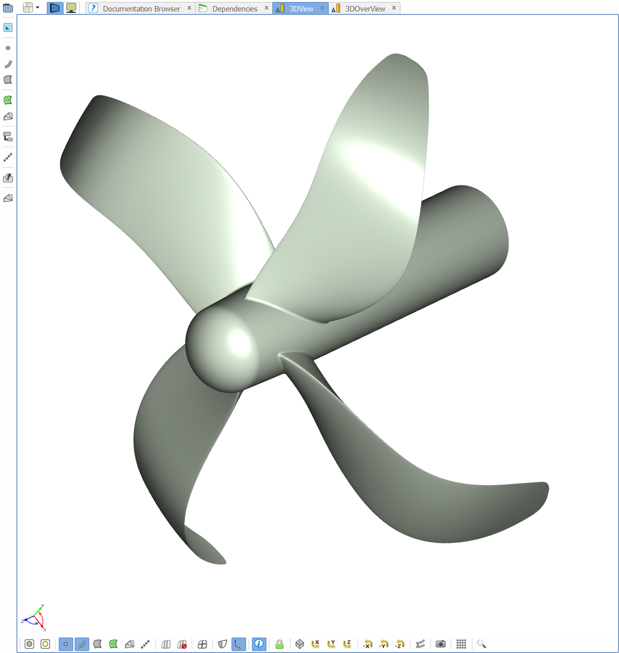
Hi
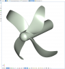
Here is new propeller stuffs!
It runs just on Version 4 platform.
Enjoy :) !
Daehwan
Query about curvature in CAESES
in Miscellaneous
Posted · Report reply
Hi Motofumi,
The geometrical and mathematical definition of surface curvature in CAESES is all the same with the general one.
Therefore surfaces created in CAESES also has the same property of curvature with that of other CAD.
If the issue were just to adjust the curvatures at a boundary between two neiboring surfaces, we could make it in CAESES.
As far as I am understood from your post, it seems that you are looking for a method of fairing series of surfaces maintaining same curvature values and their boundaries.
In that case, the issue is not a matter of two-surface-connection any more and we need to pay extra efforts to make a fairing system within CAESES.
Neverthless what you want to have is just two-surface-connection maintaining curvature at the boundary, please upload the surfaces that you want to connect.
Then I will try connecting them.
Cheers
Daehwan