


Rizuan Razali
-
Content Count
11 -
Joined
-
Last visited
Posts posted by Rizuan Razali
-
-
Thank you for your replies, Mr. Claus. I will take note of that.
-
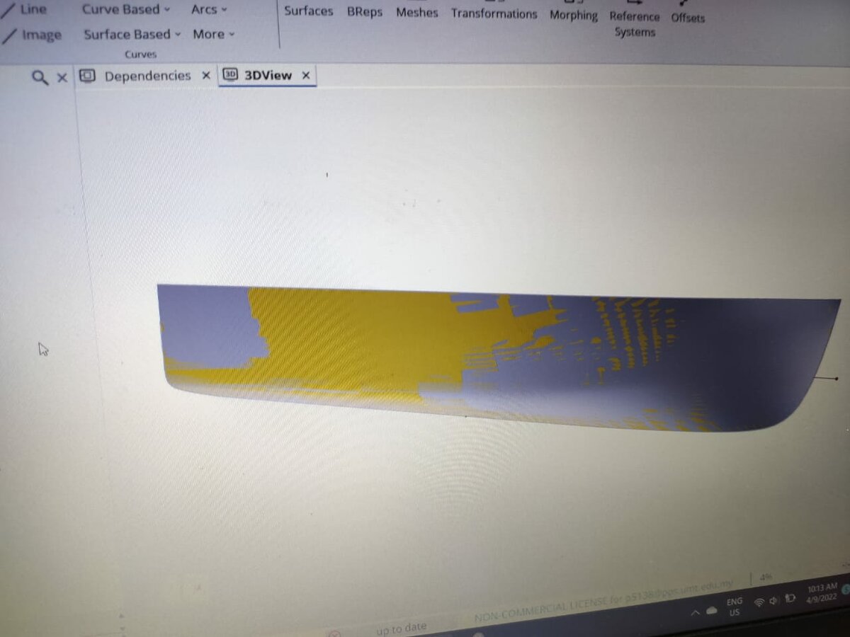
Greeting everyone,

The geometry that I want to export to IGES is the yellow one, which is the optimum geometry. The silver colour is the initial geometry. It was supposed to look like that when I did the comparison.
However, when I export optimum geometry and do the comparison in CAD Rhinoceros, the geometry has changed. It became like this:
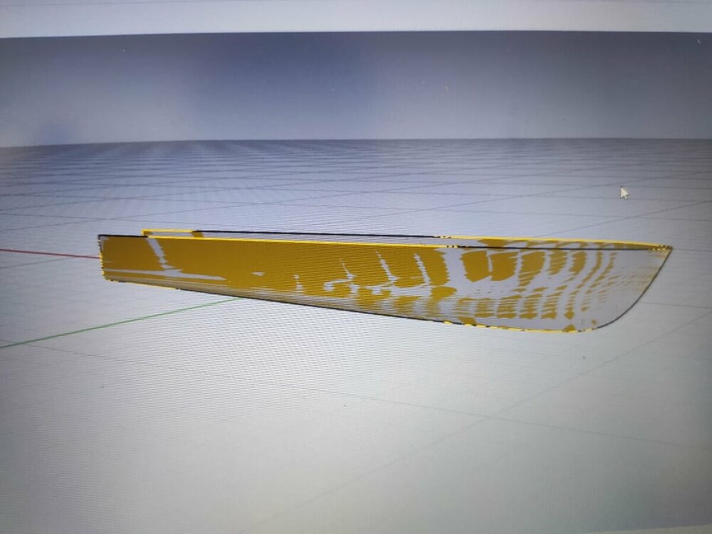
I hope you guys can help me figure out how to export optimum geometry correctly and how to solve this problem. Thank you.
best regard,
Rizuan
-
Hi, Mr. Heinrich,
First of all, thank you for your reply.
I wanted to create an image surface of my initial hull to do the optimization by using the Lankendby method in order to find the optimum hull form. However, this time the initial hull form consists of many surfaces, approximately 180 surfaces, as I attached below. It is complicated to do image surface 1 by 1 of the initial hull.
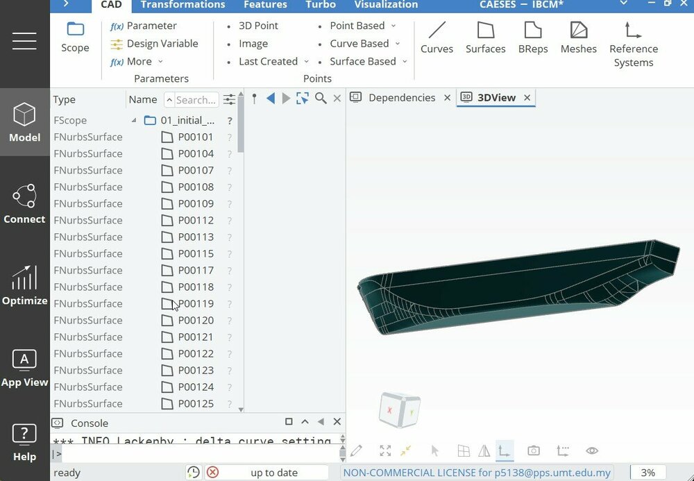
I already tried your suggestion, but it also makes an image surface from a single surface, not all the surfaces that I put in breps.
best regards,
Rizuan
-
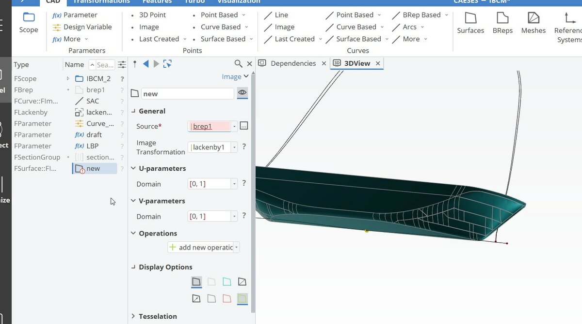
Greeting everyone,
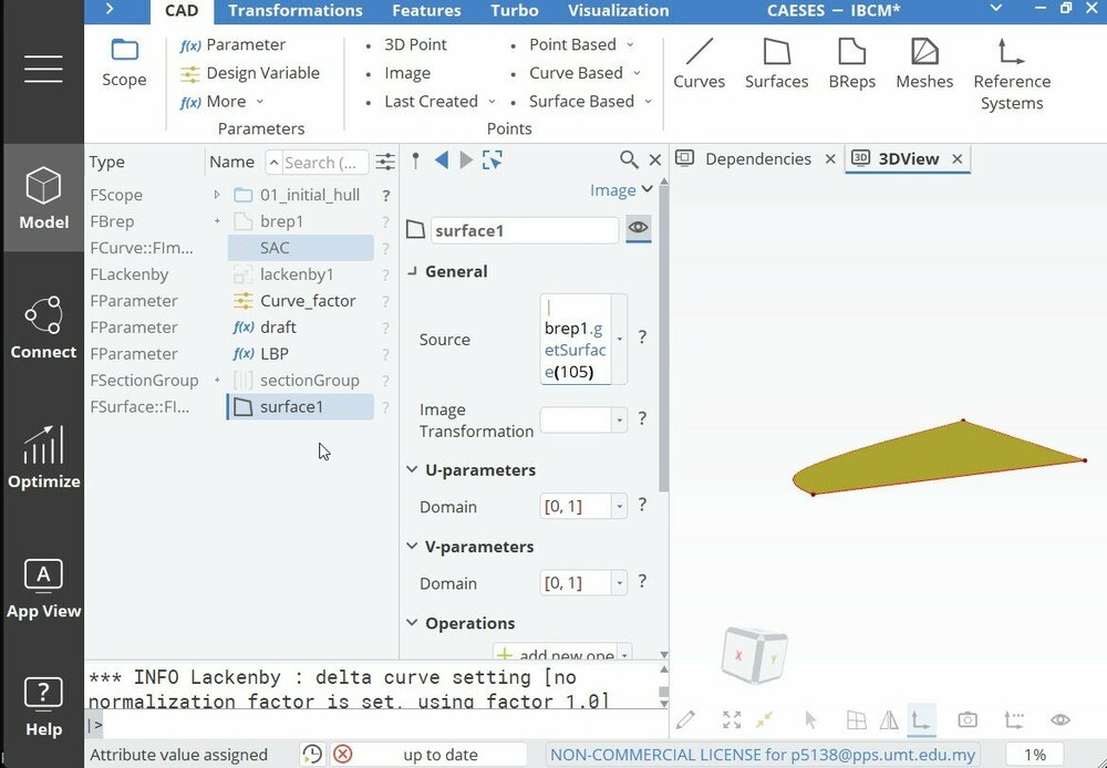
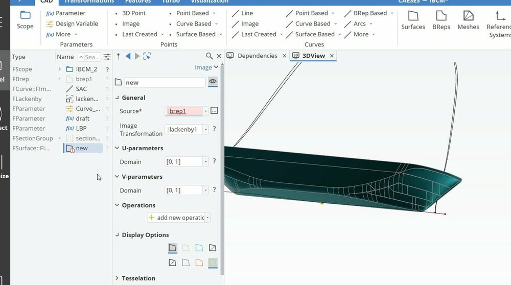
Currently, I am trying to do optimization of a hull form that consists of many surfaces. Then I put all the surfaces together using "breps". However, when I tried to generate an image surface at the source part, it looked like I had failed to put "Breps" as the source for the image surface. I have attached a picture below for your reference. What can I do to put that "Breps" as the source? I hope you guys can help me with this problem. Thank you.
-
Dear Mr. Heinrich, Thank you so much for your help
-
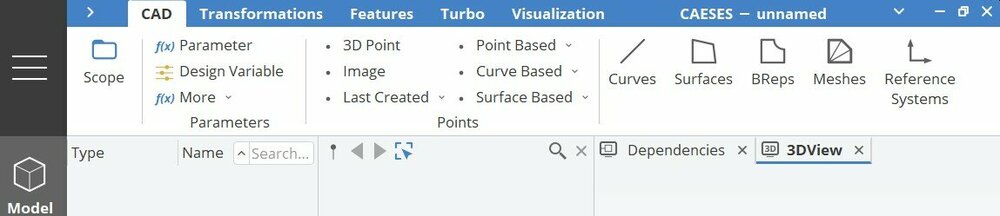
Greetings, I just updated CAESES today. Unfortunately, after updating, the offset part is missing in my CAESES control. I have attached the pictures of before and after the update. I hope you guys can help to find that offset control. Thank you.
-
Hi Mr Heinrich,
The CFD software that I will is NUMECA FINE MARINE, currently my institution on progress to buy the license.
Best Regards,
Rizuan
-
Hi Mr Heinrich,
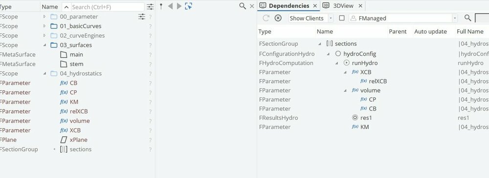
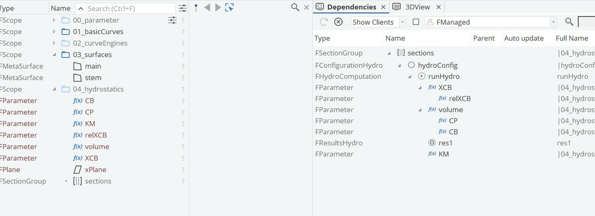
First of all, thank you for your sir. I already go thought for the tutorials in CAESES, such as hull form modeling using delta shift and lackenby method. However, I unclear about how to put Rt (total resistance) in the set up and how to make the flow of dependency as I attached below. Thank you.
Regard,
Rizuan
-
Greeting everyone,
I’m a postgraduate student from Malaysia. Currently I doing research of optimization of ship hull form towards reducing total resistance. However, I just a beginner in this CAESES software. I really seek for your guidance. If anyone have an example how to optimize ship hull form, can I have that file to use as my reference. Thank you.
-
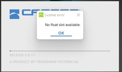
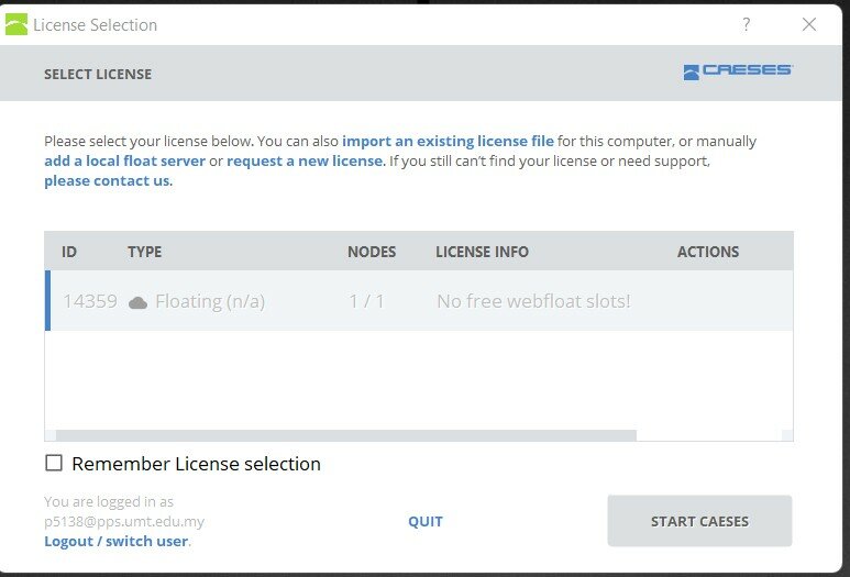
Greeting,
Something happened when i traying to login into CAESES. it say no float slot available. Can someone help me. Thank you.


Export geometry to IGES
in General Modeling
Posted · Report reply
Hello, Mr. Claus. May I ask you to please explain how to draw those lines on the buttocks exactly as you have shown above? I've already looked for tutorials. But I couldn't find anything about it. I can only do curve sectional area. I'm hoping you can assist me with this issue. Many thanks.