


Mr. chris baki
-
Content Count
28 -
Joined
-
Last visited
Posts posted by Mr. chris baki
-
-
On 11/10/2020 at 10:01 AM, Mr. Heinrich von Zadow said:Hi Chris,
for some algorithms, there is such an option (e.g. TSearch offers a "Variable Tolerance" -- if all design variables do not change significantly w.r.t. this value then the engine is stopped), but not for all.
Cheers,
Heinrichthanks. 🙂
-
Hello to everyone,
Is there any way to input a criterion of convergence when running an optimization algorithm like NSGA-II ?
Thank you,
Chris
-
Yes sure, i had it in mind too.
I ll need some more time though to finish it, clean it up and maybe some more queries :)
Thank you for your help,
Chris
-
Hello mr.Heinrich,
Thank you for your detailed explanations.
You are right, i had it set back at 15 because nomatter what i tried yesterday did not wok out, cant tell why..
Anyhow, i tried again now and the result is fine. If i set the number of interpolted points in surface direction of MainSurface above 35 and leave that of FrontSurface at 15 everything seems to run smoothly.
Thank you very much for your up-to-now assistance,
Chris
-
Hi Vahid,
Please follow the procedure below;
Close all CAESES instances.
Remove the following files:
%PROGRAMDATA%/boost_interprocess/FS_LICENSE_SHM2
%PROGRAMDATA%/finterprocess/FS_LICENSE_SHM3
Start CAESES (without admin rights)
Please let me know if the problem is resolved or not.
Cheers
Ceyhan
Hello everyone,
I had a similar problem. 80% of times i tried to open a second Caeses project i got rejected and kept seeing that message (maximum number of 2 instances reached)
Deleted the above mentioned files and up to now everything seems to run smoothly.
Thank you,
Chris
-
Good Afternoon mr. Heinrich,
Thank you a lot for your quick response.
1) ... That's the role of unit speed? To make it easier for the ruled surface between 2 curves with different length?
2) I see, yes now it is ok. But how did u refer at the Hull Brep to cut and trim Skeg Brep? If i open at Hull Brep menu i see nowhere Skeg Brep as input....
Sth else to mention: If i tried to implement the other way (the one mentioned at fastmonohull exemple) in order to cut n trim skeg the biggest problem i have is that the edges of the subsurface seem really different than the original ones. I increased the resolution properties to 500x500 but the same problem.. (see attached images prob3&4.png)
3) i use version 4.4.1. For me the problem remains...(see attached .probRemain.png).
Moreover, i want to ask for one more thing concerning my version. 50% of the times i try to open a second Caeses project i cannot. How can i resolve this? Because i would like sometimes to check 2 projects simultaneously and now i can say that possibility depends on chance... ?!?
Thank you very much,
Chris

-
Hello mr. Heinrich,
1) I asked about the image curves because when the ruled surface was created from the multisegmentsmoothcurves the result wasnot that good. On the contrary with the use of image curves 9and unit speed trck) the resulted surface is better, so i guess there is some difference...
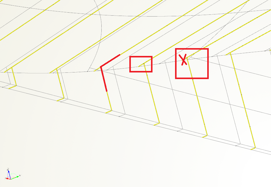
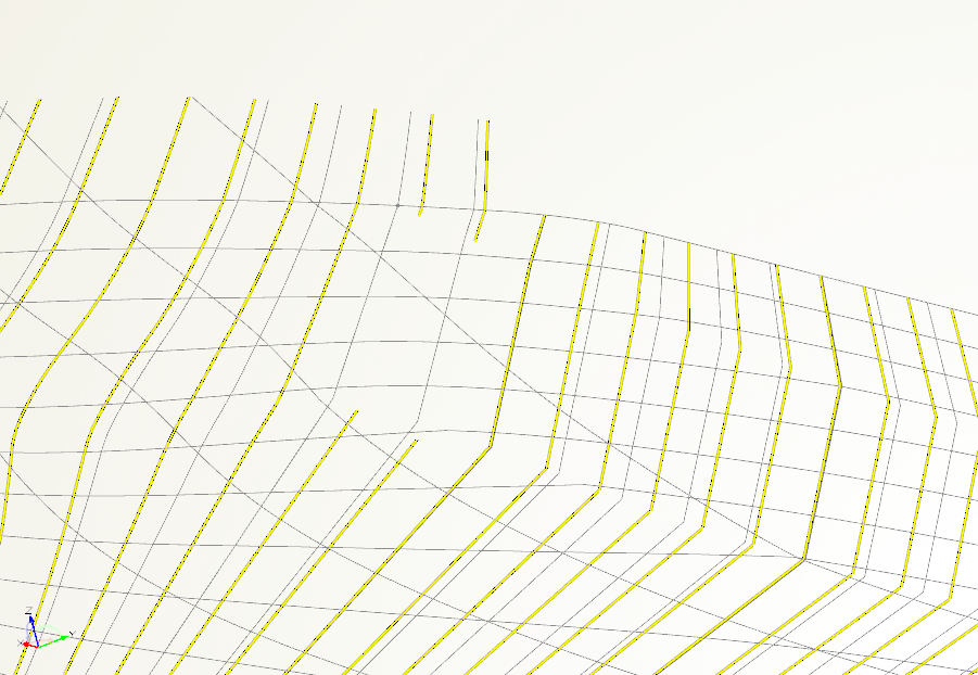
2) Anyhow, I have still the same problem for which i asked help for the skeg connection. I mean when i use Brep i get the same problem concering the sections produced over the skeg region (coupling of hull and skeg is not correct, the section line describes both hull and skeg which is wrong... - See attached image problem1)
3) As far as it concerns the front region of main metasurface, i increased the number of interpolatedpointsinsurfacesirections from 15->75 but the result is the same (attached image problem2) and of course if i increase the corresponding number in frontmetasurface, the bow sections change/almost competely dearranged..
My main problem is the skeg region because i can get the right sections towards chineLow end if i just insert the a groupSurface as source at sections instead of Brep... Still, though i dont get why if i utilize Surfaces as input the sections are ok (at x 32m approx.) and if i use Brep the problem remains...
Thank you,
Cheers,
Chris

-
Hello thank you for your answer but new queries keep comin,
1) Can u explain a bit or give some hints(maybe a link etc.) why u prefer to use the image curves and why the result is better?
2) I changed a little bit the for part(CL_FOR) of Chine Low (decreased breadth 5-6cm) and the upadated Brep presents a hole at the for end of main metasurface? If i just create sections from surfaces i have no problem though...
3) Brep is really fine but if i wanted to create the subsurfaces etc. what would be the right way of thinkin? I mean should i have splitted the main surface in smaller parts?
Thank you,
Chris
-
Thank you for your answer,
1)I inserted a rail curve (an image curve of the CPC_1) but the problem remains. To be honest, when i did that it seemed that problem got solved but after 1 day and changing some other things irrelevant it seems that i am in the same situation. So, can u help me fix that and basically explain me why that happens? Since the main meta surface gets CPC_1 as a curve (CPC_1 runs for sure at z= 0) how can that happen? Also when i try to create an image curve of CPC_1 again if i zoom i see the image curve at different pos compared to CPC_1, also if i change the Parametrization it moves a bit up or down...
One more question concerning the skeg, Which images sould i create? I mean i create aft_sub1 and aft_sub 2 but thy present differences than the original metasurface. Specially, aft_sub2 seems to do a little zig-zag close to the stern. Also, if i try to trim metasurface (create image of it and put the projection point p2 as in fast monohull exemple) it seems to change even more...Why that happens? Which is the correct way of advancing on that matter?
2) concerning FrontSurfaceTry i see that there is a small hole at the connection between main_metasurface and FrontsurfaceTry at z=2m approx. Why is that happening ? rail curves etc. are all set...
Thank you very much for your help,
Chris
-
Hi,
I can tell a few things based on my up-to-now, realtively small, experience.
It ,really, depends on which curves you inserted, which parameters you want to adjust, what kind of transformations you want to apply, and in what extent you want to parametrize your project.
If your imported curves have relatively few points and you can control them, you can just hold a copy of them as reference and then just start to insert parameters on the points you want to adjust. On my case though,where the imported nurbs curves had lots of points, difficult to adjust, the way that i went thought is the following: Recreated the basic curves and maybe a few auxilliary ones(bsplines,fsplines/lines etc.) and then started to create the surface in order to achiece to close it nice and create a starting hull as similar as possible to the imported one. Then parameters...
Are you going to recreate the hull in caeses for cfd calcs where meshing surface is critical or just the curves (waterlines,section,cpc etc.)? I am telling this cause i still have some problems in closing my surface/hull perfeclty.. I think you can just create your offsets even if the hull is ot not closed fully for your hydrostatics. Also,obviously, the more curves you have, its easier to control your vessel but changes in shape will be less probably.
You can check, as well, the files i exchanged through here in order to get some ideas or try things.
Have fun,
Chris
-
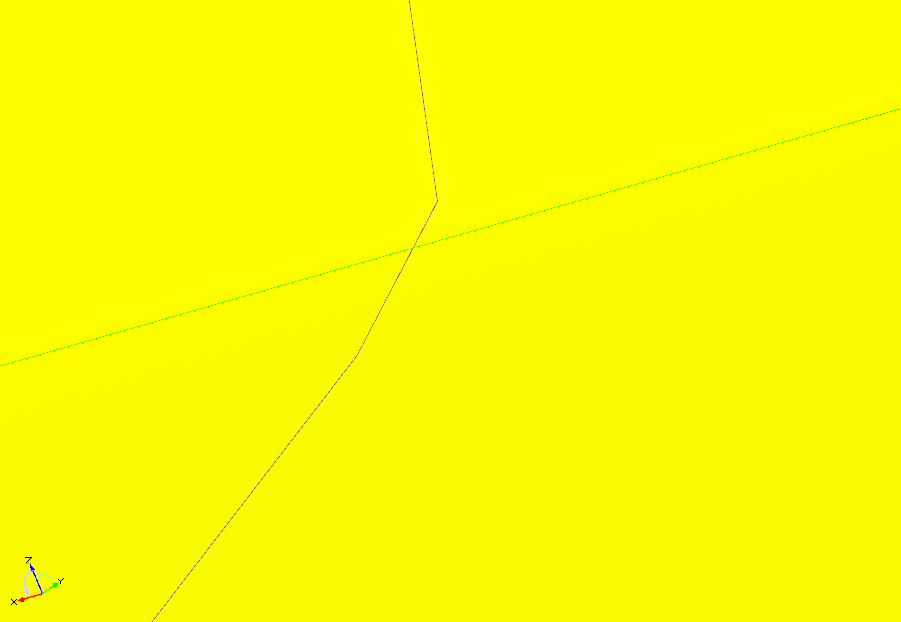
Good afternoon mr. Heinrich, thank you for your tips. I was really depressed when i could not see the chines properly aligned with the knuckles of the surface. Now, please i think i need some more hints.
When i try to create my skeg-> Projection Skeg top (as in fast monohull) i notice that the end projection point appears at z=-0.003 (x=11.4) approx. .When i zoom in a bit more, i see that the main surface in some points along x-pos (CPC_1 curve) takes negative z-values?? Can this be happening? Is that related with the failure at the created skeg? Moreover, can that be related with the other warning i get about an internal pole in main surface or in "prostego" ??
I am grateful for your help,
Chris
-
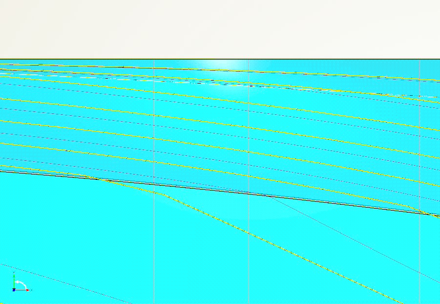
Hello Mr. Heinrich,
I tried to increase the resolution to let's say 500x500 but.. If you allow me, my concern is that when i get the sectons/waterlines as offsets of the surfaces i can see those small differences as shown in the pictures posted. I notice that the edge of the surface doesnt meet the chines. Is that caused by the resolution ?
Thank you very much for your support.
Kind regards,
Chris


-
Hello Mr. Heinrich,
Thank you for your answer, i understand that curves should be fair enough but my curvatuere porcupine shows some sudden changes of curvature that i dont want anyhow...
For the time, my biggest problem is sth else. I just realized that that my 2 chine vessel actually is not a 2 hard chined vessel like it should be. I mean that the knuckles of sections in most cases do not pass exactly from the chines, it has a small curvature near the knuckles and not a sharp corner. Can you help me on that? i read somewhere about the bevel method but this is way too far advanced for me. Is there any other way possible to achieve that sharpness on the edges defined by the Up&Low chines??
Thank you very much for your assistance,
Chris
*I know i have some problem on the edge of main surface and front surface but i think i gonna resolve that. For now, the sharpess is my number 1 priority...
-
Good morning to everyone,
Hello Mr. Heinrich,
Ok, so far so good. I, still, have some technical issues to firure out but i ll get back to those later on.
For the next step, i d like to evaluate the smoothness of surfaces 'n curves created. The traditional way. let's say, is to check each section's or waterline's curvature graph, adjust them, update them respectively and run through that cycle several times...
1) For now, i still haven't found out the tools provided to check the curvature of curves or surfaces (so i exported an .iges, opened it at another program and assessed the curvature of curves 'n surfaces which in some points isnt good enough or the desired one). How can i isolate each section/waterline and check their curvature since they are offsets generated from surface interpolation? Should i just make new interpolated curves from surface ?
2) Concerning my design, the things that i can change to improve smoothness of the curvature are only the basic curves (Profile, Deck, Up&Low Chines, and maybe some angles at the bow region), am i right?
3) Do you have any other way of approaching that problem to suggest?
Thank you,
Chris
-
Hello Mr.Heinrich,
For one more time, your example helps me a lot to understand and each time i get more 'n more new questions...
I uploaded the SupplyVessel example. From that example i wanted to use the StemRadius feature in order to create my bow shape but again i misunderstand sth concerning the entrance angle curve etc. so i cannot recreate it at my ship.
I get fully your point about the connection of the main surfaces and the front part so itried to follow your feature example.
Firstly, why your parameter runs up to 0.666???
For my case shouldnt i just create a zPos curve so that the waterlines will run at full height of the vessel? The result is disappointing though so i feel it sth more than that(Feature:frontSurface). i mean, the curve doesn't even close at the stem at any z, moeover it exceeds the deck height etc.I feel i am running into the same problems that i meet while copying from the FastMonohullExemple the bow part creation method.
Also, every time you refer to the bow profile you keep starting at 0.01m above baseline. Aren't we missing a small part at the lowest edge of the bow that way?
Allow me one more question regarding now the aft part of the vessel cause I am trying to create a skeg and i am looking at the FastMonohullExample. When i try to create the projection curve it just shows up split in 2 or sometimes 3 parts(the separated part appears at 0,0,0). If i change the width of the skeg it works fine but i d like to create a really thin one - 5cm@AftPart and 10cm@ForePart- but keep getting wrong the projection curve. What am i missing here?
I want to read the tutorials again but i keep getting lost while trying just to finish this project ...
I sincerely thank you,
Chris
-
Good morning Mr.Heinrich,
Thank you for your tips, and i ll start now trying to design them. So, some questions cause i really have not understood some things.
Up to now i have 2(A& B) versions of bow surface but none of them is satisying, therefore i am trying to design versions 1&2.
A) SURFACES->BowLow&BowUp : The sections (under Nomeis&Isaloi scope) have an angle at the bow region at wareline's Z.
B) I created a metasurface up to 40.4m (SURFACES->NewBowUP - which btw has an overlap behind 31.8m for which i dont understand the reason) and then i closed the bow surface with a fillet surface(SURFACES->BowWithFillet): In that case sections seem ok and they have the desired flare but the waterlines have a breaking point towards the bow region which i dont like.
1) I am trying to create the bow surface as the exemple in fast_monohull but i am having a hard time. My secondFwdSurface is my SURFACES->NewBowUP but after that i get confused on how to create the correct lines(stem angle,xPos etc) in order to design my stem surface. Could you give me some help on that ?
2) I m trying to applicate another way that i read about at the Supply_Vessel_Exemple uploaded at the forum. In this case i m trying to follow the exemple for its StemRadius feature but again the results are discouraging. Could u advice me on that as well please ?
*i drew the sections under NewSectionScope just for my help in order to undestand visually the differences resulted from some parameters i tried to change. They are not actually used for the design.
Thank you very much.
Best regards,
Chris
*haha, B) is B ), without the gap
**my 1 case is under scope StemTRY
-
Good morning Mr.Heinrich,
Thank you for your tips, and i ll start now trying to design them. So, some questions cause i really have not understood some things.
Up to now i have 2(A&B) versions of bow surface but none of them is satisying, therefore i am trying to design versions 1&2.
A) SURFACES->BowLow&BowUp : The sections (under Nomeis&Isaloi scope) have an angle at the bow region at wareline's Z.
B) I created a metasurface up to 40.4m (SURFACES->NewBowUP - which btw has an overlap behind 31.8m for which i dont understand the reason) and then i closed the bow surface with a fillet surface(SURFACES->BowWithFillet): In that case sections seem ok and they have the desired flare but the waterlines have a breaking point towards the bow region which i dont like.
1) I am trying to create the bow surface as the exemple in fast_monohull but i am having a hard time. My secondFwdSurface is my SURFACES->NewBowUP but after that i get confused on how to create the correct lines(stem angle,xPos etc) in order to design my stem surface. Could you give me some help on that ?
2) I m trying to applicate another way that i read about at the Supply_Vessel_Exemple uploaded at the forum. In this case i m trying to follow the exemple for its StemRadius feature but again the results are discouraging. Could u advice me on that as well please ?
*i drew the sections under NewSectionScope just for my help in order to undestand visually the differences resulted from some parameters i tried to change. They are not actually used for the design.
Thank you very much.
Best regards,
Chris
-
 1
1
-
-
Hello Mr. Heinrich,
How are you? Hope everything goes well.
So, I studied a bit and tried a few things around and i am about to start enjoying designing with Caeses. Still, though, i think i need some more help.
I changed a bit the length of the vessel (no prob) and i tried to recreate the bow surfaces using metasurfaces. I wanted to give some more flair at the bow region (which i could not achieve if coon patches were used/or at least was not the desired flair, you can see if you click at existing offset_group "sections"), therefore i used 2 fsplines (as you can read at the scopes (New_Bow_down,New_Bow_Up). But the results are not 100% correct.
i cannot achieve to close the surface at the ForEnd, which curves i should use???
Also, there is an ovelap of the surfaces behing 31.8, eventhough both of them should start at 31.8m ??
Finally, there is a problem at the transom area because the section created there goes up to around 2m instead of 4m, can you tell why?
If you have time plz guide me a bit more around.
Thank you very much for everything,
Chris
-
*One more thing.
Between Boat2 and Boat3, there are many differences at the waterlines. I mean Boat2's waterlines are much more smoother specially towards the bow region even though the basic curves are the same. Is it due to the way front surfaces are created? The resulted shape may differ that much?
-
Good morning Mr. Heinrich,
Thanks again and let me start with my questions concerning file Boat_2.
1)Via feature SimpleTwoKnuckleSection we create a bspline curve that connects points p1,p2,p3,p4 with degree 1. After that via the engine we can create many bsplines from the 4 basic curves (Cpc, ChineLow,ChineUp,Deck), along xPos Curve.
2)After that via MetaSurface we create the desired surface from the Aft_end up to 31.8m (or ChineLow:end).
3)Next, we create the image surfaces just to ensure the continuity between MetaSurface and the 2 surfaces at the bow via that U-Paramter Domain [|SURFACES|main|metaSurface:edge2.ft(2, |misc|WL:start:z), 1] ?
4)Why do we use the imageCurves for the definition of BowSurfaces? to ensure, once again, continuity? If we had used the initial created curves (to define the bow region-under ScopeMisc) we would have problems, right? Also, at the definiton of image Curves we use Source and Domain in order to get the full length of curves??
5)If i want to use BrepExtrudeEdgesToPlane i need to downlaod it, cause i cannot locate at Breps menu? it is just used to close the surfaces?
6)Finally, how have you designed waterlines, sections, buttocks and they are constantly shown, plus i cannot select them or isolate them? can i deactivate them? They are not offsets? Because
These are my questions for now,
Thank you again in advance,
and i know i owe you at least some pines of beer,
Cheers,
Chris
-
Mr.Heinrich,
I am really grateful for your help. Allow me to study a bit these designs, run through the tutorials again and come up later on with some questions.
Kind regards,
Thank you,
Chris
-
Sorry once again, i am posting my up-to-now design for my yacht. One thing is that I am having trouble to create the upper part of stem, if i dont follow the path of creating a curve engine and a metasurface i wont have any results?
Also, why i cannot generate waterlines up to 2m? I get the warning that sections cannot be generated, even though i cant see where is the mistake...
Thank you, once again,
Chris
-
Hello Heinrich,
Thank you very much for your help. Ok i think i got it, what you did with the generic curve and it is probably the most appropriate solution. I will try to redesign my boat with the suggested approach later today. For now, i would like to continue my current design in order to understand better Caeses and generally CAD. So, if you allow me i d like to pose some more questions and if possible tell me which are my mistakes at my design and way of thinking for the design.
First, i d like to ask again what would be the most suitable way to edit the imported Nurbs curves (let's say the deck curve in order to maintain the same curvature and dimensions at deck (Scope:OR_Data->Basic Curves Original) and how to interpolate them at my redesigned boat (New_Sections, New_Chines) ?
Secondly, most importantly, i have trouble creating the surfaces from the curves i ve drawn, so i d like some help creating surfaces at rhe current design.Is it possible to create the desired surfaces or i have to redesign the curves from the beginning? Of course, i admit the your proposed way is much more efficient and i ll try to apply it at the next design and also that i need to gine more details at my bow.
Big thanks to all of you in advance, and as you may feel you are the only source of advice within miles.
Best regards,
Chris
CAESES / STARCCM+ on Ubuntu Inst.
in Installation
Posted · Report reply
Dear all,
i am trying to use a relatively old Alienware/Dell machine for some SBDO using CAESES / STARCCM+ on Ubuntu..Despite the effort, i cannot figure out what is missing and CAESES_5.2 cannot launch. I have tried using Ubuntu 20.04/22.04/24.04 LTS but no result. Pls find attached screenshot1 containing the output error and screenshot2 showing PC's specs.
1)Can you advice on above matter ?
2) Would you suggest any other linux distribution that would allow for a smooth operation/integration of CAESES / STARCCM+ concerning the machine described above ?
Thank you very much for your support,
Kind Regards,
Chris