


Ms. Nabila Naz
-
Content Count
28 -
Joined
-
Last visited
Posts posted by Ms. Nabila Naz
-
-
Hello,
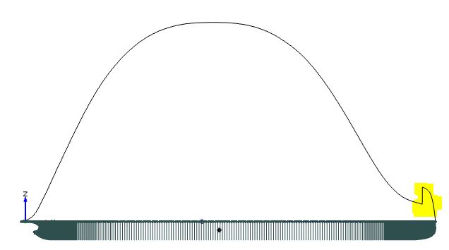
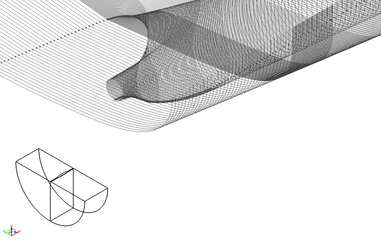
I am trying to perform Lackenby shift for KCS hull. But after computing hydrostatic calculation, the initial sectional area curve does not maintain uniformity at bow of ship (screen-shot attached)
Would you please tell me how to make it uniform i.e., make the curve smooth without any break at forepart ?Regards,Nabila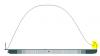
-
Thank you very much Stefan for your link.
Have you done any Shipflow CFD analysis for JBC with Energy Saving Device (ESD)?
Regards,
Nabila Naz
-
Hello Everyone!
Can anyone please send me the IGES file of Japan Bulk Carrier (JBC) Ship with Energy Saving Device (ESD)?
Thanks in advance
Nabila Naz
-
Hello,
How can I get Shipflow readable offset file from existing IGES file using CAESES-free? I have tried to obtain the offset file from JBC.igs using CAESES but I could not do it. Though it is possible to get offset from iges in Shipflow but the iges file I have, can be imported in CAESES but not supported by Shipflow.
I have found that CAESES has that option in feature but do not know how to implement it?
Anyone please help me to get offset file JBC(Japan Bulk Carrier)
Regards,
NAbila
-
Hi Daniel,
Thanks a lot for your co-operation. Please check your email.
Regards,
Nabila Naz
-
Dear Matthias,
Thank you very much for your detailed instruction though it is not clear to me right now as I started using CAESES-free very recently; but I am trying to better understand your instructions. You have mentioned that " I can better understand the sample setups by "Show Dependency" function by right clicking the objects"..does it mean the objects under the baseline?
Yes, I am working wiith Shipflow for 3 months and I can perform CFD simulation with it. At present, I want to optimize bulb of KCS using CAESES-free
so that I can optimize the resistance by Shipflow CFD simulation. As I am using Shipflow Design, it is not integrated with CAESES and in CAD > Transformations > Shifts >
....there is only Lackenby shift option..no Surface Delta Shift option. For that, I think that if I can transform the bulb through CAESES and then import the new offset to shipflow can get CFD results for various bulb transformation. I am not sure whether is it possible or not? Would you please suggest me which path should I follow to get optimized result of Ship resistance for KCS hull with bulb transformation?
Best Regards,
Nabila Naz
-
Can I get the step by step tutorial of the following sample for optimization?
" KCS Bulb Transformation with Surface Delta Shift (B-Spline Surface)"
-
Hi Jeorg,
I have got help from this forum several times previously and its very helpful forum for getting instant help. Shipflow has no forum like CAESES. Thanks for your contact link.
Have a Good Day!
-
Hi!
I am trying to investigate hull-propeller-rudder interaction using Shipflow. For that I want to import external grid for rudder.
How can I import external grid generated by external grid generator for rudder/propeller in Shipflow?
Thanking you,
Nabila Naz
-
Hi!
I am trying to investigate hull-propeller-rudder interaction using Shipflow. For that I want to import external grid for rudder.
How can I import external grid generated by external grid generator for rudder/propeller in Shipflow?
Thanking you,
Nabila Naz
-
Thanks Björn Regnström for the web address.,
-
Hi Karsten,
Thank you very much for your detailed instruction.
Yes the problem is solved :) .
Cheers,
Nabila
-
Hi Nabila,
The geometry is scaled so that Lpp=1 in all Shipflow computations, and the origin is translated to x=FP and z=undisturbed water level.
Best regards,
Björn Regnström
Flowtech International AB
Hello Bjorn,
You said that The geometry is scaled so that Lpp=1 in all Shipflow computations, and the origin is translated to x=FP and z=undisturbed water level.
That means if I give original offset data Shipflow itself will scale it to Lpp=1? or I have to nondimensionalize the offset data myself before Shipflow computation?
Regards,
Nabila
-
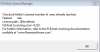
Hello Björn Regnström,As you are from Flowtech International AB. I am sharing my another problem during Shipflow simulation. Could you please explain me what it means?I am running Shipflow xchap with a container ship iges. But after computation I do not get result. Instead the following message appears in outful file.- OUTPUTThis card was not found.Default output will be used:Interpolated grid -> XVGRID-fileCoarse grid -> XGPOST-fileIteration history turned offerror in subroutine stretc4 zm - z1 is too close to zerostretc: ErrorRegards,
Nabila
-
Thank you very much Karsten Wenzke and Björn Regnström for your informative reply.
Actually, I can not contact the shipflow support because the maintenance and support facilities date for our license is expired and there is no scope for renewal at here now. That's why I am posting various problems that I faced during performing my Shipflow simulation and I am also very grateful to all members of //www.caeses.com/forum, for their instant support in each every problem I faced.
Thanks again.
Nabila
-
I am running Shipflow xchap with a container ship iges. But after computation I do not get result. Instead the following message appears in outful file. Anyone could please explain me what it means?- OUTPUTThis card was not found.Default output will be used:Interpolated grid -> XVGRID-fileCoarse grid -> XGPOST-fileIteration history turned offerror in subroutine stretc4 zm - z1 is too close to zerostretc: ErrorRegards,
Nabila
-
Hi Karsten,
This is in the shipflow design tutorials- basic. Here is the link: http://www.flowtech.se/tutorials/shipflow-basic-training-tutorial.
Cheers,
Nabila
-
Hi Karsten,
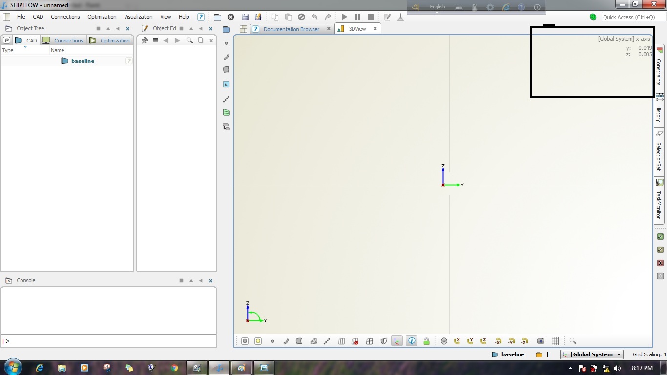
Following is the attached picture of my previous 3d view with Global coordinate which is absent in my present 3d view. I have used the filters x y z or -x -y -z but it does not appear.
I have changed the 3dview colour to plain color due to some graphics problem, is it the reason of missing global coordinate in 3d view?
Thanks
Nabila

-
I am practicing Shipflow basic tutorial. In tutorial 7_4 of XGRID manual control, a kcs offset file is used. But after running computation I have found that ComponentOutline tool is created small size than the original offset file and it is also not around the original hull of the ship (see attached photo).
Is it correct? If so why it is like that?

Nabila Naz
-
Hi Joerg,
I have reset to factory settings but the problem remains same.
Regards
Nabila
-
Thanks Arne for your reply.
-
Thank you very much Tobias Stein for your informative post.
I am using Shipflow for my university research purpose. My assignment is to analyze how RANS solver (xchap, xgrid) works in Shipflow.
To analyze it, I am facing problem of undersatnding command of xgrid, xchap and how to deal with them? Could you please help me in this topic?
Regards,
Nabila Naz
Bangladesh University of Engineering and Technology
-
I have found the following error message(attached pic) during EnsembleInvestigation using Shipflow. Would you please explain it?
Nabila naz
-
In my Shipflow 3Dview window, x, y and z cordinate dimensions are missing. But it is present in 3d overview (Like [Global System] z-axis, x:0.0, y:0.0). How can I get back it 3d view?
Nabila Naz
Bangladesh
Problem in Lackenby shift
in Miscellaneous
Posted · Report reply
Dear Matthias,
Email has been sent.
Thanks