


Mr. Bodo Hasubek
-
Content Count
25 -
Joined
-
Last visited
Posts posted by Mr. Bodo Hasubek
-
-
UPDATE:
CAESES 4.4.1 comes with the lastest libpng12.so.0.59.0 and all the symbolic links set correctly (so forget about steps 1. - 4- below).
However, removing libz (step 5) is still required under (K)Ubuntu 18.04.
ORIGINAL POST:
CASES 4.3.1 doesn't run on (K)Ubuntu 18.04 out of the box because it requires libpng12 that isn't readily available for 18.04.
Here my work around:
- Get libpng12 (64-Bit) from https://packages.ubuntu.com/xenial/amd64/libpng12-0/download
(This is the latest version for (K)Ubuntu 16(!).04)
- Extract libpng12.so.0.54.0 from the downloaded .deb package (I used ark and just looked through the file until I found it in /lib/x86_64-linux-gnu)
- Copy libpng12.so.0.54.0 to the lib-directory of your CAESES-Installation (usually something like ~/CAESES_4.3.1_Linux.x86_64/lib/Linux.x86_64)
- Set the symbolic link ln -s libpng12.so.0.54.0 libpng12.so.0 (in the lib directory)
- REMOVE libz.so libz.so.1 libz.so.1.2.5 from yor CAESES-lib-directory
(They are too old and apparently the newer version comes with 18.04)
- Make sure your proprietary graphics driver is installed.
Worked like a charm for me. Hope it helps.
Regards,
Bodo
-
 1
1
- Get libpng12 (64-Bit) from https://packages.ubuntu.com/xenial/amd64/libpng12-0/download
-
Hi Carsten,
That's what I needed to known. The parametrization aspect is really interesting. I didn't expect that, but it makes sense.
Thank you,
Bodo
-
Dear all,
I would like do have a defined accuracy for my imagecurves and offsetcurves.
I found two settings that may influence that:
1) .setNumberOfEvaluationsForParametrization()
2) .setApproximationTolerance()
(both apparently work for imagecurves and offsetcurves)
Questions:
i) What exactly do they do and what is the interaction/dependence between these two parameters?
ii) Which one should be used?
iii) What are the standard values for those parameters? (I couldn't find the corresponding get... functions)
Thank you and kind regards,
Bodo
-
1
-
-
I take the part that the Breps export nicely to Rhino3D back: Only the original surfaces get exported, not the true intersections which is kind of pointless then...
-
Hi,
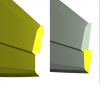
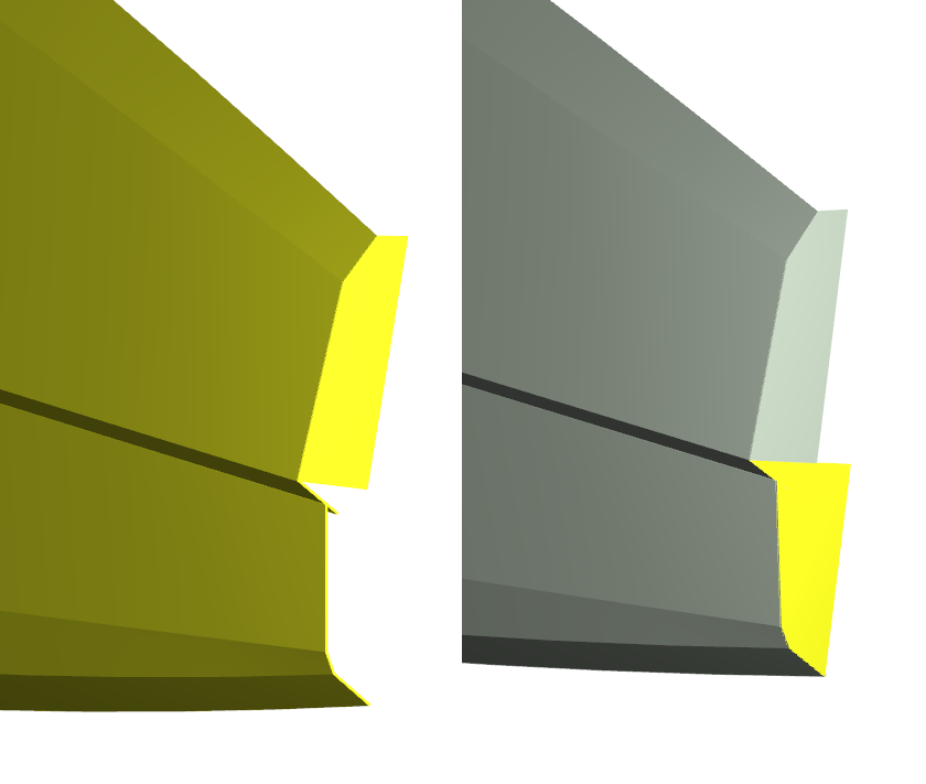
I am trying to (ab?)use BReps to create a ship hull model with real plate thickness (not just the outer surfaces), since they import nicely into RHino3D.
All plates are created as a closed Breps using a self-written feature that basically takes an outer hull plate and makes a 3D plate-BRep from it with a given plate thickness. Then I try to union as much from them together as possible, since they provide really nice joining lines when they work.
However, I keep on running into trouble when I try to make a union from several such plates.
For one thing, it appears to depend on the order in which the plates are added to the union.
Another problem is shon in the picture:
On the left side, keeping the "correct" order and only using "simple" plates I could union all the plates as shown. As soon as I try to union the additional plate shown in yellow in the right picture, the whole BRep display disappears. To give some hints, where the problem may come from, I would like to point out, that the new plate has a "nasty" shape and connects to several plates.
Any ideas where the limitations of BReps lie and how to circumvent them?
Thanks,
Bodo
-
Hi Carsten and Jörg,
thanks for the replies.
I already wrote a feature that interpolates perpendicular points, no problem. Good enough for ship building ;-)
I'm actually using it to create stringers along my hull surfaces. So in the ideal case the first and the last points should have the same x-coordinate as the original surface curve. However, that need's to be fixed manually for this special case, since this is an extra assumption.
Cheers,
Bodo
-
Hi all,
I am fighting a bit with offset curves. The plan is to create an offset curve that is perpendicular w.r.t. to a surface curve on a given surface.
So I set up a domain curve and set it as the ThicknessCurve in my offset curve.
Nothing useful happens, unless I enable "BothSides" and at least a "BlendingPositionLE".
However, I want neither: Neither an Offset on both sides, nor rounded edges.
Here's the program snipped:
// s is the surfce to which the offset should be perpendicular,
// dc is a domaincurve created before
surfacecurve base(s, dc)
// Domaincurve for constant offset
line dcOC([0,1,0], [1,1,0])
offsetcurve offs(base)
offs.setDistance(NULL) // Disable fixed offset
offs.setThicknessCurve(dcOC)
offs.setThicknessFactor(0.1)
offs.setBothSides(true)
offs.setBlendPositionLE(0.01)
Am I missing something?
Regards,
Bodo
-
Hi all,
thank you very much for the solution. The second paramter of getmax() slipped my attention.
And, yes apparently there is an accuracy problem if "ft()" is used in conjunction with "getmax()".
Regards,
Bodo
-
Hi everybody,
I am experiencing an accuracy problem using curves:
The curve is a NACA4digit profile that is translated, rotated and scaled in a transformation chain in order to put it into the right position and orientation. At the end the rounded part of the NACA profile is at maximum x position and the profiles chord is not aligned with the x-axis (which actually makes no difference. I tried an x-aligned version with the same result.).
Then I run the following command, in order to get the maximum position on this curve in terms of t, since I would like to use that in an imagecurve to cut out a portion of interest:
NACACurve.ft(0, NACACurve.getMax(0))
This command consistently delivers the rear end t (which is 1), while t should be somewhere close to 0.5.
Apparently the maximum position in x direction found by getmax(0) is larger than the maximum x position the ft-command finds when traversing the curve, such that no match is found and the ft command ends up at t=1.
Since the error is rather persistent I created a simple file that shows the problem: c3 is the transformed NACA curve we are talking about. p1 marks the x-position where the maximum should lie according to the "getmax(0)" command. p2 shows the x position of the NACACurve.ft(0, NACACurve.getMax(0)) command.
Any ideas?
Thank you,
Bodo
P.S. I am using the Linux version 4.0.0 if that matters. But this error is far older if I remember correctly. So if it has been just fixed in a 4.0.x just let me know.
-
Hi Arne,
thank you for the quick response. Never mind I'll just use a double series an do some typecasting for the time being.
And you know, this stupid question I posed is all you fault ;-), because I studied your very nice booklet "Effective Feature Programming" in depth to write better features... Thanks again for that booklet, I really love it.
Regards,
Bodo
-
Hi all,
I kind of hate to post such stupid questions, but I am trying to use an FIntegerSeries as an argument to a feature since that can by nicely abused as a typed array, but I couldn't find it in the type list of the arguments tab.
Am I just to blind (there are many types and I tried to look carefully through all of them with no success)?
Or is there a reason why this basic type is missing?
Or is it just missing by accident?
Thank you for your help.
Regards,
Bodo
-
Hi Arne,
I used the foreach loop and all the compilation errors (apply button) went away. Must have been a stupid typo somewhere that I didn't spot.
Thanx a lot,
Bodo
-
Hi all,
I wrote a feature that creates a 3D plate of a given thickness from a surface as a solid and calculates for example the mass of the plate and stores it in the double variable Mass.
Now I would like to drop a whole bunch of these plates into an FEntityGroup (FObjectList exists only inside features afaik) and give it to another feature that calculates the overall COG of all the plates.
Inside this feature I am having trouble to access the elements of my feature objects. A castTo(FFeature::<feature_name>) didn't work for me.
What am I doing wrong?
For example I would like to sum up the masses of the plates like that (plates is the FEntityGroup parameter of the feature):
while (i<plates.count())
masses += plates.at(i).castTo(FFeature::SurfaceTo3DPlate).getMass()
i += 1
endwhile
Why does the castTo() not work or what is wrong with it?
Thanks a lot,
Bodo
-
Hello Arne,
a million thanks for the answer - and the warnings.
Regards,
Bodo
-
Hello all,
I generated a whole bunch of FDesignResultTables commonly know as the result tables shown after an optimization or ensemble investigation run.
Now I would like to collect all that data into one table, in which I consolidate several design runs into one line etc. This in general is not a problem, since all the values of the FDesignResultTables can be easily accessed. It possible for example to generate a script file that would do this task for me, since I know how to generate the names of the FDesignResultTables I would like to access. Obviously all FDesignResultsTables are somehow attached to the main scope of the application, because they can be diectly accessed in the command line.
However, it would be much more practicable if I could leave out the step with the script generation and directly iterate through a the list of all FDesignResultsTables from within a script, read the names and/or type (in case other object types are in this list as well) an decide what to do with it.
Is there an internal object that I can access that holds all the FDesignResultTables (and possibly others)?
Thank you,
Bodo
-
Hi Arne,
I promised to give some feedback. Here once again what I am trying to solve:
I have an Excel/CSV table with a set of parameters that define the geometry of my sail boat hull which I created as a parametric model in FFW. Now I want to use an EnsembleInvestigation to run SHIPFLOW for different Froude numbers on each design variant defined by those parameters to find out which ones are most favourable for my desired speed range.
In the course of my experiments I figured out that in theory it would be sufficient to change some model parameters and run my EnsembleInvestiagation. The driving force was make data recovery from all calculations as simple as possible. So I tried the following approaches:
- Write a Feature that loops through my design parameters and starts my EnsembleInvestigation (EI) after the parameters are set.
Result: The designs created by the EI.run() did not show up properly in the designs tab and I ended up with a currupted fdb-file. - Do the same as in 1., but with a scipt. The specialty was to change the EI's name each time around to be able to identify the designs later.
Looks like this (whereby ModelNo = n selects my model parameters from a table and thus changes the model, "MeinEnsemble is the orginal name of the EI):
baseline.edit()
ModelNo = 1
MeinEnsemble.setName("Design_0012")
Design_0012.setUseResultPool(FALSE)
Design_0012.run()
ModelNo = 2
Design_0012.setName("Design_0013")
Design_0013.setUseResultPool(FALSE)
Design_0013.run()
ModelNo = 3 ...
Result: Worked nicely up to the second design. Then for no reason the name of the EI changed back to its original ("MeinEnsemble") in the middle of the second run of the EI. Obviously the remaining script lines crashed because the name of the EI had changed (and thus did not exist as expected). The advantage of this approach would have been that all EIs belong to the same design which makes data collection easy. - Implements the original idea as discussed at the beginning of this thread, that is to create a new design manually properly naming for each geometric variant (parameter set) and run the EI there. In order to avoid reloading of the model parameter data table in each Design, the model parameters are set explicitly using the script. Looks like this:
baseline.edit()
design(NULL,NULL).setName("Design_0012")
dDraft = -0.95
dDraftX = 9
dBWLmax = 0.8
dBWLmaxX = 9
dBWLrear = 0.75
dSecAX = 9
dSecA = 1.3588743
MeinEnsemble.setUseResultPool(FALSE)
MeinEnsemble.run()
baseline.edit()
design(NULL,NULL).setName("Design_0013")
dDraft = -0.95 ...
Result: Could be run sucessfully for 5 Designs for 5 Froude numbers in each design. Apparently a re-visiting of the designs is not necessary since the EI appears to take care of all updates. I'll try this approach for 200 designs now. Data collection not solved yet, but I put all the values of interest into the result table views, which are easy enough to access. We'll see what I'll do with it.
Obviously the scripts were all created using different features.
I hope this helps if anyone is interested in trying similar things.
Regards,
Bodo
-
1
- Write a Feature that loops through my design parameters and starts my EnsembleInvestigation (EI) after the parameters are set.
-
Hi Arne,
yes, your answers hepl a lot. I think now I have most things sorted out.
I'll let you know if I run into trouble during the implementation fro my particular case.
Thank you again. I really like your competent and thorough answers.
Regards,
Bodo
-
Hi Arne,
thank you for your explanations. They brought some light into the darkness, but as you anticipated new answers trigger new questions ;-)
The setup given above only revisits the main designs created within the script using the design(NULL, NULL) command while the design engine(s) within these designs will create a bunch of sub-designs for the SHIPFLOW evaluations. Is it enough to only revisit the main designs in order to trigger a proper update of all sub-designs?
Since I don't know when the SHIPFLOW calculation finishes, how do I know, when to run the revisiting? What do you mean with making the script wait if there is a while-loop?
As long as only one computer is used for the SHIPFLOW computations, the simplest way to avoid these update problems would be to serialize all the evaluations of the DesignEngine, i.e. Let the DesignEngine only create one sub-design with one SHIPFLOW calculation at a time, completely finish it and go on with the next SHIPFLOW evaluation. After the DesignEngine is done, continue with the script. But this is apparently not possible when I use external calculations, is it?
Thanks again,
Bodo
-
Hi Arne,
thanks again. You kind of lost me at the following sentcence:
"In case your evaluations trigger asynchrounous processes (i.e. external programs that will cause objects to become pending), this should work as well. The only pitfall is that, as opposed with regular design engines, the changing back into the designs once they are finished is not done automatically. However, to achive this is not straight forward (unfortunately)."
As far as I understand, my SHIPFLOW calulation are normally run asynchronously by my EnsembleInvestigation (they all turn orange until they are finished)
I don't understand the bold print sentence. What exactly happens or does not happen when asynchronous evaluations are run and why is it a problem?
As far as I understood your feature snipped you basically creates an FObjectList of the names of all the design names.
Since FObjectLists cannot be created on the console, you put this list as an argument to the feature reEvaluateScript which you then access in the script using ".getDesigns()". In the feature you reEvaluateScript simply "re-visit" all designs.
So far so good, but why is that necessary? Because the script doesn't wait for the pending evaluations? Do I have to wait for the calulations to finish before I run the reEvaluateScript?
Just enlighten me, please ;-)
Regards,
Bodo
-
Hi Arne,
thank you so much!
This is exactly what I wanted to do. The trick appears to be that when the commands are executed in the console they "follow" the changes of the design before the remaining commands are executed. Obviously this could be done at least theoretically by walking along the object tree of a project within a feature, but that would create much more overhead than a simple context (design) switch as used in your proposal. It should be easy enough to create the appropriate scripts using a feature.
I am quite happy reading my design parameters from a CSV file. COM's not needed, but thanks for mentioning.
Regarding, the last part of collecting the results in a new design results table. This is clearly desirable. Could that be achieved automatically/programatically? (As I said we are looking at several thousand designs, thus just touching them all only once is a pain). If it's just about values I could probaly just add a few script lines to store those to an external file, if the file access functions in CAESES allow for appending to an existing file (I haven't checked that).
Thank you very much again,
Bodo
-
Dear all,
I have a hull design that depends on several parameters. In a first run I used an EnsembleInvestigation to find feasable designs whereby I did some parameter optimization.
Now I would like to use the feasable designs as input parameters combinations for a SHIPFLOW analysis. Of course this could be all done in one step, but I would like to be able to add some designs manually in an Excelsheet to compare my intuition with hard mathematics. Furthermore, I would like to accumulate the results from several SHIPFLOW calculations per design (basically looking at different Froude numbers) to calculate a parameter to rank the designs based on these several SHIPFLOW calculations. Manual evaluation is out, because we are talking about several thousand results. Obviously I would like to name the designs in a way that I can easily trace them back to my input parameter sets. I already wrote a nice feature to import an arbitrary CSV file into a table to get my desired parameter combinations into SHIPFLOW.
Now I see two principle ways to solve that:
- I could try to create an EnsembleInvestigation in which I try to manipulate the hull parameters before I start SHIPFLOW and after it finishes. I tried that, but ran into some problems (furthermore this is not my preferred way)
- I could create a feature that sets my hull parameters, creates a copy of the design and runs SHIPFLOW in this newly created design (this approach looks preferable to me since better control is possible).
I am experiencing some difficulties with approach 2 as well: I cannot create a copy of the baseline within the feature that apperears properly in the Optimization tab. If I do a copy from the console using design(getcurrentdesign()) I only get an empty new design. How can I create a complete copy within a feature that properly appears in the Optimization tab? How do I change the current design? Can I start an EnsembleInvestigation in such a new design from within my feature?
Or: Is there an easier better way to achieve my goal?
The easiest solution -at least to start with - would be if I could provide the EnsembleInvestigation with valid tupels of parameters only, but I couldn't figure out if that's possible.
Many thanks,
Bodo
-
In Framework 2.x I used a command like the following without any problem:
hull.addoffset(brokenOffset.setEqualCoordinates(0,newXPos))
where hull is of Foffsetgroup type, brokenOffset of Foffset type and newXPos some double value.
This command does not work in FFW 3.0.1 anymore ("Could not resolve command"), because it turned out that setEqualCoordinates() no longer returns an FOffset object, but an FPolyLine object. Knowing that the problem is easily solved using a type cast:
hull.addoffset(brokenOffset.setEqualCoordinates(0,newXPos)).castTo(FOffset))
I can not say if that's a wanted change or a bug, but it's esily solved anyhow.
Bodo
-
Hi Stefan and Daehwan,
thank you for your replies. Really a nice trick, Daehwan. I don't think any changes are required as long as it is properly documented and there is a simple way to create a deep copy - which there is as I just learned. Just copying references has its merits too: It's faster.
Apparently my problem has dissolved as well: The new shipflow 5.0 defines the standard coordinate system as I did: Position [0,0,0] is now at the aft perpendicular using a standard right hand rule coordinate system.
Regards,
Bodo
-
Hello,
I'am playing around with offsets and offsetGroups in order to match them to the standard coordinate orientation of shipflow to avoid problems there with setting the correct coordinate frame.
I was a bit confused, that statments like
offsetGroup originalGroup(<fill in some offsets here>)
offsetGroup copyOfGroup(originalGroup)
would no create a deep copy of all the points of all the offsets in the original group: When I modified the coordinates of the offsets of the copyOfGroup using setEqualCoordinates(...) I always would modify the original points of the original offsets in originalGroup. That is not really what I expected. That means that the second statement above does not create a deep copy of the original group but rather a copy of the list of references to the original sections. Is there any particular reason for this behaviour?
Thank you,
B. Hasubek
Area and COA calculation on custom plane
in General Modeling
Posted · Report reply
Hi Simone,
as far as I know you can evaluate Area and COA of a curve only with respect to the principal planes and main axes.
In principle you now have two options:
1) Find a transformation that puts your (flat) curve into a principal plane. Use rotation and translation in a transformation chain to do that. Might be difficult though if you don't know the transformations.
Using this approach it might be an option to create your curve in a principal plane, use your normal getArea() and getCoA() commands an find transformation to put your curve in the right position. You can then use the same transformation to transform your CoA point.
2) Make a surface out of your curve by connecting start and end point with a line. Then use .getAreaApproximation() on that surface for the area.
Unfortunatly there is no CoA command for arbitrary surfaces, afaik. A work around would be to create a symmetrical solid around your surface. Then use .getCoG() on this flat solid. Since the solid is symmetrical around your surface CoG = CoA.
If anyone knows of simpler ways I would be glad to learn it too.
Regards,
Bodo