


Ceyhan Erdem
-
Content Count
210 -
Joined
-
Last visited
-
Days Won
12
Posts posted by Ceyhan Erdem
-
-
And I have figured the problem with the unit update as well,
In fact it was a problem within the fsc script, that gave an error.
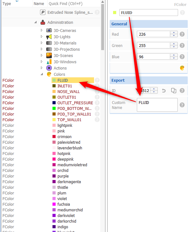
Please check your color labels within CAESES. Seems you have created a white space that is transferred to the fsc script as "/n"
Getting rid of the white space solves the problem.
Cheers
Ceyhan
-
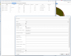
Hi Anup,
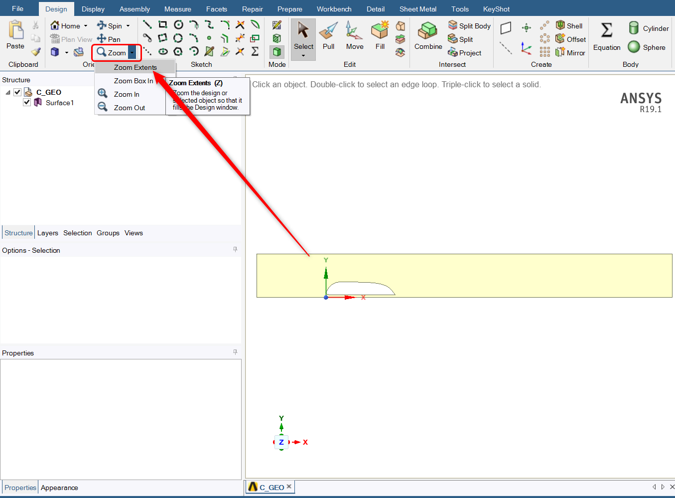
Can you please check the attached picture?
I think within SpaceClaim clicking on the Zoom to Extends button will help you to visualize the geometry.
I have figured there is still a unit problem due to the fact that this is a surface body. Will fix this today.
Cheers
Ceyhan
-
Hi Anup,
Please find below the link for an updated version of the ACT App that would fix the SpaceClaim unit problem including some other little bugs.
Cheers
Ceyhan
-
Hi Anup,
Will check the case and let you know once I have a solution.
Cheers
Ceyhan
-
Hi Ogbenna,
Yes, you should be selecting the scope containing the geometry desired to be exported.
Cheers
Ceyhan
-
Hi Ogbenna,
Have you already checked the ANSYS ACT App tutorial within CAESES. You can find the mentioned document under;
Documentation Browser > Tutorials > ANSYS ACT App
or alternatively,
Documentation Browser > Help > ANSYS ACT APP > Integrations > ANSYS ACT App
If not, I highly recommend you to go over the document first.
You can create your Flow Domain within CAESES, assigning colors to let's say inlet / outlet / wall /interface etc.. boundary locations and then create a CAESES batch file which you will be using with the ACT App.
Please let me know if you have further questions.
Cheers
Ceyhan
-
Hi Ashesh,
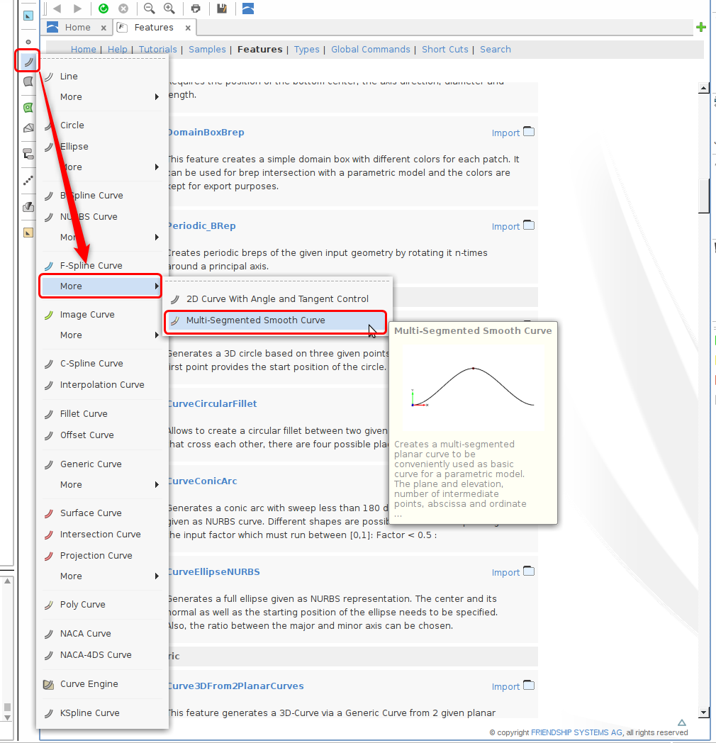
I guess you are using an old version of CAESES.
Within the new version, which is the v4.4.2 the tutorials are updated accordingly.
In either case, you can find the mentioned curve under Curves within the toolbar between the object tree and the 3D viewer.
Please check the attached picture.
Cheers
Ceyhan
-
 1
1
-
-
Hi MooSung,
Please check the attached modified project.
The modified simple feature might give you an idea how to use it.
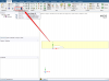
Coming to your second question please check the picture below.
In this scenario when the value of N equals to 7, the argument H will be hidden in your created feature.
Note: you have created the argument N as FDouble, maybe you would prefer to assign it as FUnsigned
Cheers
Ceyhan
-
1
-
-
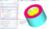
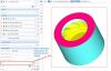
Hi Bastian,
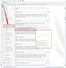
In SpaceClaim there is a certain situation that we observe. When no color is assigned in CAESES; within SpaceClaim strangely one of the face assigned colors is directly assigned to the entire volume.
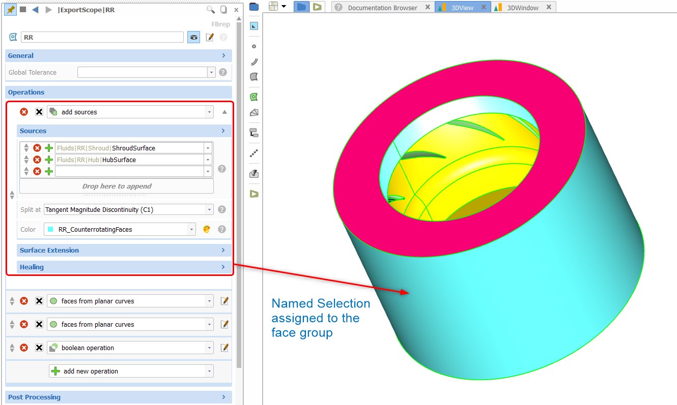
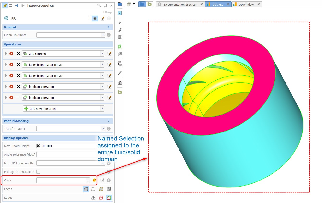
And that was the problem you were facing. In order to resolve the problem I will recommend you to assign a color to the entire BRep.
At the bottom of the BRep menu , under Display Options you can find the location where you can create/assign BRep body colors
However those colors assigned to each operation becomes a Named Selection for a face group
Note: This problem is not observed in DesignModeler
Cheers
Ceyhan
-
Hi Anup,
1) For the Named Selection creation within SpaceClaim, please go to;
File > Space Claim Options > File Options >general
and disable the option "Use SpaceClaim color tones when importing"
This is also mentioned in the Ansys ACT App tutorial file within CAESES
2) As Joerg has mentioned I would recommend not to use a polycurve since it will provide you a single loop.
Why don't you create a 3D model with a defined unit depth?
You will be able to assign named selections within CAESES. In the mesher you can create a mesh with single element in depth direction.
But also I would like to keep in my radar to find a way for transferring some specific curves/lines using ACT which can be distinguished and used in IcemCFD.
3) With the new upcoming CAESES version and the provided updated ACT App there will be the possibility for the user to transfer CAESES units to SpaceClaim/DesignModeler
Cheers
Ceyhan
-
Hi Bastian,
They should be updating simultaneously.
What kind of error messages do you get?
Maybe you can share some screenshots with me.
Cheers
Ceyhan
-
Hi Bastian,
Please check the attached tutorial for CAESES TurboGrid ACT App which is also included within CAESES.
In order to include several components, let's say n rows of rotor, m rows of stator what you have to do is to create n+m (in this case) TurboGrid export features within your project.
Please check and let me know if the problem is resolved.
Cheers
Ceyhan
-
Hi Carola,
Are you using the ACT app for CAESES within ANSYS workbench?
If so for each ANSYS DesignPoint you will have a separate CAESES Project with its related folders. At this point ANSYS is the tool that controls where the folders would be located.
Please let me know if you need further assistance.
Cheers
Ceyhan
-
Hi Andreas,
If the mentioned tool that you would like to couple with CAESES has the capability to run script files or run in batch mode, then the connection should be quite straight forward.
Please let me know if you need further assistance.
I will recommend you to check the Software Connection tutorials within CAESES and the batch scripting commands of "Maxsurf Motion" within its manual.
Cheers
Ceyhan
-
Hi Bastian,
Are you using TE cut-off within the feature?
Cheers
Ceyhan -
Hi Bastian,
Can you please send your project to erdem@friendship-systems.com?
I will give a look and try to figure out the problem.
Cheers
Ceyhan
-
Hi Vahid,
I am sorry but within a Feature it is not possible to rename an already created object.
In the Feature definition the objects are named during compile time only.
Maybe you would like to do workaround by creating an imagecurve with the name you would like to assign.
Cheers
Ceyhan
-
Hi Vahid,
Please follow the procedure below;
Close all CAESES instances.
Remove the following files:
%PROGRAMDATA%/boost_interprocess/FS_LICENSE_SHM2
%PROGRAMDATA%/finterprocess/FS_LICENSE_SHM3
Start CAESES (without admin rights)Please let me know if the problem is resolved or not.
Cheers
Ceyhan
-
Hi Priyanka,
So you have a data set that you want CAESES to read it and create a hull form ?
Cheers
Ceyhan
-
Hi Chien,
Please find the attached simple project.
This might give you some idea about how the operations are defined. Besides that please check the sample "Axial Fan" under Documentation>Samples
For three airfoil sections, I have defined chord scaling, pitch, yaw and rake. This is just for illustration purposes to show how the steps are performed.
Of course you would like to perform those steps not one by one but using a Feature Definition, and as a result obtaining a Meta Surface.
Note: I have figured some errors in the code that I have attached earlier which are corrected
Cheers
Ceyhan
-
Hi Andreas,
Sorry for the late answer. Have tried so far the create the connection?
It should be compatible, creating no problems.
Please let me know if you encounter any.
Cheers
Ceyhan
-
Hi Chien,
Under Documentation Browser > Samples;
there is the Propeller Setup example. I will strongly recommend you to check the mentioned model and go over the Curve Engine, Meta Surface tutorials.
If you have any further questions, please do not hesitate to ask.
Cheers
Ceyhan
-
Hi Chien,
If you replace the translation to cylindrical transformation within the feature you can reach your goal. Maybe you would also be interested to introduce some skew pitch rake and scaling beforehand.
The Loft method within CAESES is a tight method.
Cheers
Ceyhan
-
Hi Chien,
Maybe you should start with a feature that reads your profiles.
Please check the attached simple project that reads airfoil data. Afterwards you can go over tutorial files that would improve your CAESES capabilities.
Cheers
Ceyhan


Simulating ship hulls with ansys
in Software Connections
Posted · Report reply
Hi Ogbenna,
Sorry for my late answer, I must have missed the question.
Can you please uninstall the CAESES Act App that you are using for the time being and install the one within the link below,
https://www.friendship-systems.de/fcloud6/public.php?service=files&t=19f5250d6755731feefe514eaf00d82d
Please do not forget to restart ANSYS after uninstalling the old version.
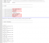
I can see that no geometry is being transferred meaning that either the BRep creation failed within CAESES or something is missing within your fsc file.
You can send your CAESES project file to erdem@friendship-systems.com including the fsc file, so that I can give a look.
Cheers
Ceyhan