


Ceyhan Erdem
-
Content Count
196 -
Joined
-
Last visited
-
Days Won
11
Posts posted by Ceyhan Erdem
-
-
Hi Nikolas,
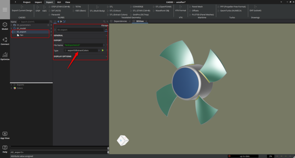
The naming for the "STL (Extract Colors)" export should be as follows;
<base name provided for exported stl>+"_"+<color name>+".stl"
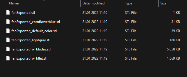
In the example provided, I gave a name "fanExported.stl". So the base name would be "fanExported"
For the blades, during the blade creation process I have assigned a user created color with a name "w_blades"
As a result the stl file for the blades ends up being "fanExported_w_blades.stl"
To conclude, if you would like to change the stl file names for the exported geometry, one has to modify the assigned color names.
I think the Tutorial;
Geometry Modelling > BRep and Solids
refers to color assignment to operations.
Please let me know if you have further questions.
Cheers
Ceyhan
-
 1
1
-
-
Hi Min,
Sorry for the late response.
Can you please provide more details?
Are you using CAESES v5? In your SoftwareConnector setup, is "asynchronous update" on (where several designs are created at the same time instead of waiting the previous design to be concluded) ?
Cheers
Ceyhan
-
Hi Nicolas,
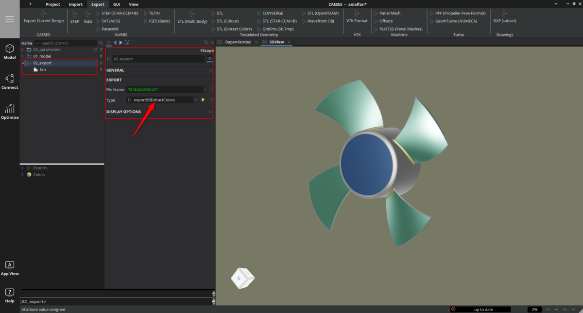
The Export type you require is "STL (Extract Colors)"
In CAESES, please create a scope, let's say "02_Export". Then please locate the BRep/s you want to be exported. Please be sure that, the geometrical entities you want to be seperated do have separate colors assigned.
Then select the folder, change the file type to "exportStlExtractColors" and provide a file name.
Using this procedure, whenever you create an fsc file, the export information will be written automatically.
Please let me know if you have further questions.
Cheers
Ceyhan
-
1
-
-
Here is the fix for the "Units xml file not found" problem if anyone encounters;
Seems like there is a certain bug in Ansys only observed on certain machines after installing a new ANSYS version;
Please go to the folder;
C:\Users\ <user name> \AppData\Roaming\Ansys\ <ANSYS version> \UnitSystems
in my case the ANSYS version was v212
There you have to modify the file
Ans.Units.config
Please search for the entry;
<UnitSystem Name="CAESES_units" DisplayName="CAESES units" BaseUnitSystem="SI" FileNamePath="C:\Users\erdem\AppData\Roaming\Ansys\v212\UnitSystems\UnitSystem_CAESES_units.xml" IsSuppressed="false" />
and delete it. Afterwards please save the file.
You have to perform this once. Due to a bug this issue is creating a problem, when a new ANSYS version is installed.
Afterwards CAESES_Workbench_App should be working just fine -
Hi Gabriel,
ANSYS DesignModeler can be quite picky sometimes. I believe there exists some degenerated faces causing the issue.
Maybe you can let me know when you may have some time for a quick web-meeting, so that I can give a look to the geometry. To be honest, there is no magical command that would pin point the problematic location.
What you can do is, to check each operation one by one and keeping an eye on the BRep warning icon.
Most probably the operation where the warning icon appears, is the cause of the problem and we should be looking around that area.
Please send an email to erdem@friendship-systems.com specifying your availability. Preferably after 1pm CET.
Cheers
Ceyhan
-
Hi Gabriel,
Your export geometry already seems to be having some issues which is the cause of you not having a water-tight geometry in DesignModeler.
The exclamation mark by the BRep icon may give you the hint.
Can you please check if you have unconnected edges as well? The command
< my BRep > .getNumberofOpenEdges()
would let you know whether you have connectivity issues or not.
I will recommend you to revise your problematic geometries.
After having checked the geometry if you still keep having the problem, please get in touch, so that we can arrange a quick web-meeting to fix the issue.
Cheers
Ceyhan
-
Hi Armagan,
I will suggest you to go over the "CAESES Geo Engine for ANSYS Workbench" tutorial carefully.
I believe you have not deactivated the "Use SpaceClaim color tones when importing" option.
You can find the above mentioned option in SpaceClaim;
SpaceClaim Options >File Options > General > Import Options
Cheers
Ceyhan
-
 1
1
-
-
Hi Farzan,
Two issues that I have figured;
1) For the blade creation at;
|05_joint|04_1_blade
operation #2; please use "add sources" instead of a "Union" Boolean Operation. Boolean operations are for water-tight geometries.
2) During the tip fillet creation;
I can see that the created surface using FiletSurface already does have some problems.
Please revise the tip creation, maybe use some guides and a LoftedSurface with derivative control instead of a "FilletSurface"
Please let me know if you need further assistance.
Cheers
Ceyhan
-
Hi Farzan,
Then I suspect there may be some existing problems on the blades you are using for the "Solid From Intersections" operation.
If not confidential, please send the model you have created to erdem@friendship-systems.com so that I can give a look and try to figure out the problems.
Cheers
Ceyhan
-
Hi Farzan,
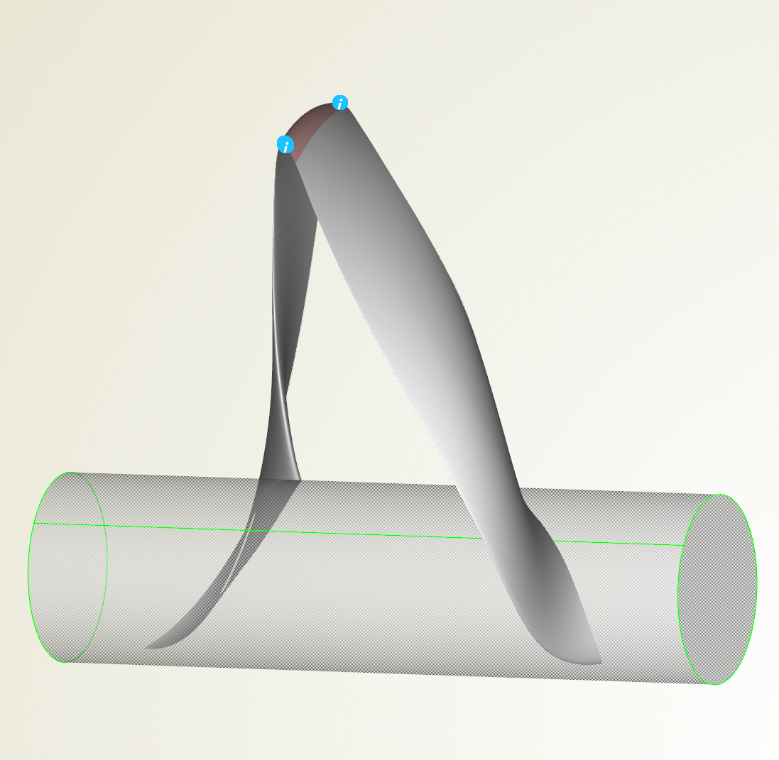
The operation "Solid From Intersections" tries to obtain a solid "water-tight" geometry from the combination of several provided geometries.
The reason why the operation provided some unsatisfactory result maybe due to your provided inputs were not much intersecting but flush maybe?
From the pictures it is not quite clear but is there even some fillet?
I will recommend you to extend the blade geometries a bit so that there can be a proper intersection among the geometries and create the fillet afterwards as a separate operation.
Please let me know if you need further assistance.
Cheers
Ceyhan
-
 1
1
-
-
Hi Armagan,
This is strange. I will suggest to have a web-meeting to recreate the issue.
Please email to erdem@friendship-systems when you may be available on the next days. I will try to fit my schedule.
Cheers
Ceyhan
-
Hi Armagan,
This is interesting. Normally you shouldn't have had any problems.
Can you please delete the 3rd line in the fsc file and give a try again?
"// Project Units millimeters"
Meanwhile I will be looking into the code to figure out the issue.
Cheers
Ceyhan
-
Hi Armagan,
Can you please let me know which ANSYS version you are using?
I suspect the version you are intending to use is not compatible with the current ACT version.
Cheers
Ceyhan
-
Hi Armagan,
Sorry for the late respond.
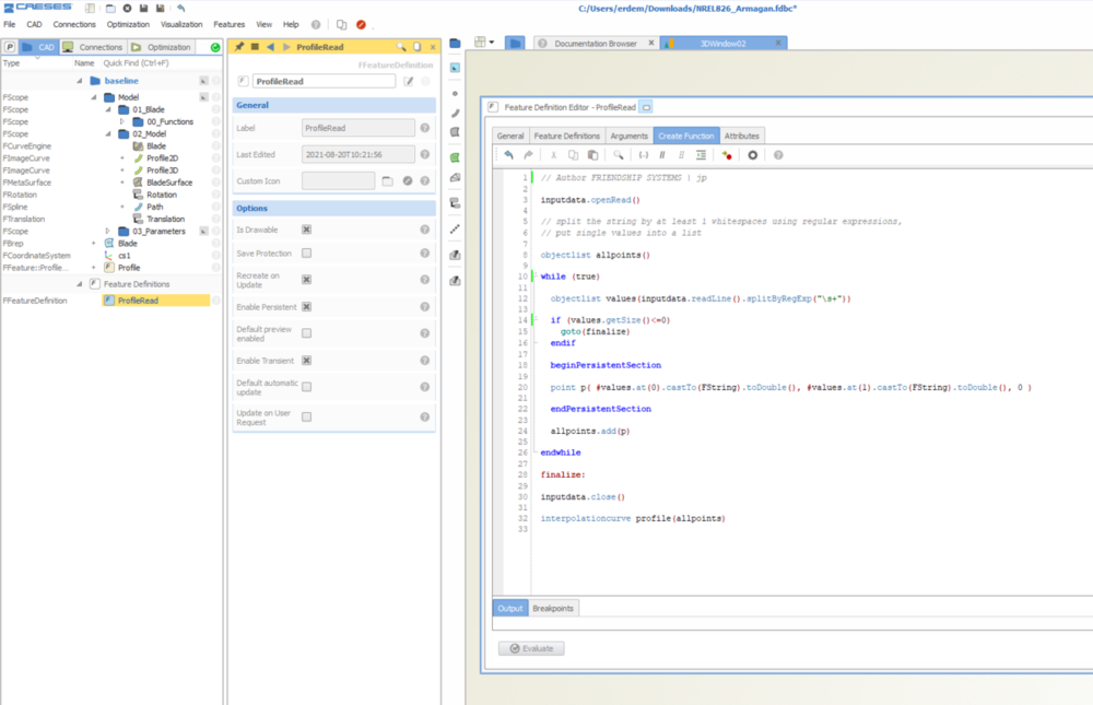
Please check the feature definition you use for the "Curve Engine" definition.
The feature definition called "ProfileRead" serves only to read a point cloud and provide you an interpolation curve as a result.
You are not changing anything afterwards. With respect to the code you are trying to create a surface out of a set of multiple profiles located at the same location.
Although you have arguments like camber, camber position, pitch and path, it seems like you are using none.
I highly recommend you to check the basic CAESES tutorials with regards to Meta Surface creation and Curve Engine.
Cheers
Ceyhan
-
Hi Gabriel,
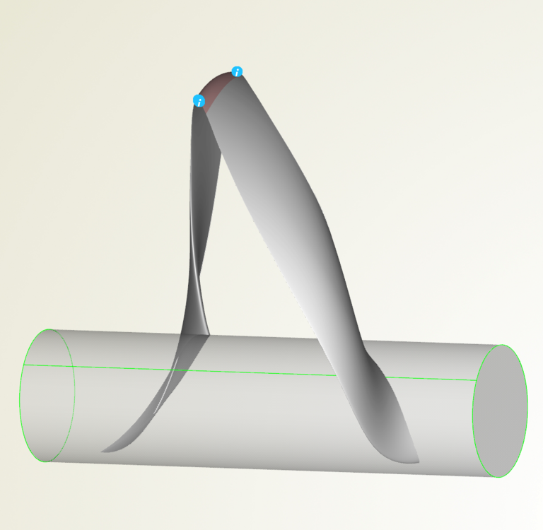
Maybe using fv_all() command would be a better alternative. Please check the picture below;
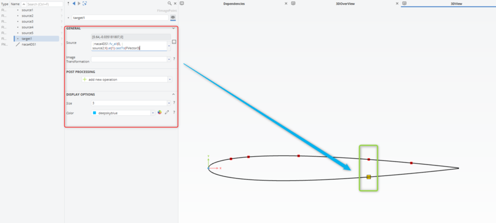
Basically, the fv_all command provides an objectlist.
MyCurve.fv_all(0,myPoint:x)
The command is applied to a curve.
The first argument "0" refers to x-axis
The second argument refers to the value on the selected axis. So result will be a list of points that have the same coordinate component value in the referred axis.
As seen on the picture above, the curve would have two locations with the same x-coordinate value. Using "at(1)" I pick the second item within the objectlist (0 would be used to pick the first one). And finally I cast the entity to a FVector3 type object.
Please let me know if you need further assistance.
Cheers
Ceyhan
-
1
-
1
-
-
Hi Armagan,
I will strongly suggest you to upgrade CAESES to 4.4.2 or 5.0.5.
Please find attached the updated CAESES Workbench App, which is included in CAESES5 installation.
Yes, you should be able to use your current CAESES version however.
Cheers
Ceyhan
-
Hi Armagan,
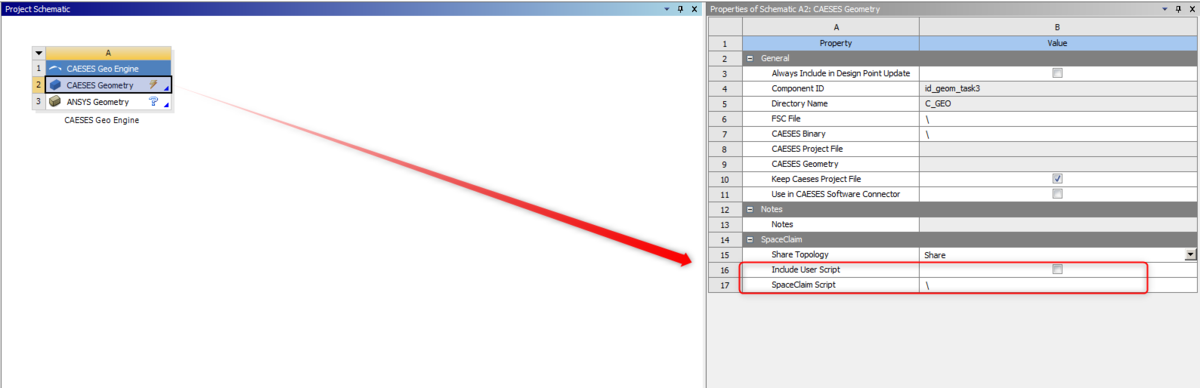
In contrary to DesignModeler, while using the current version of CAESES Workbench App, it is not possible to keep the record of the user performed actions in SpaceClaim. However I can suggest two workarounds. Either you can use DesignModeler or you can create your own SpaceClaim script and provide it to CAESES Geo Engine.
Please check the attached picture.
Please be sure that you are using the latest version of CAESES Workbench App that is included inside CAESES binary.
<CAESES5 installation Dir>/etc/ansys/
Please let me know this resolves your problem.
Cheers
Ceyhan

-
Hi Lucie,
Were you able to perform the connection with Flow 3D?
Do you still need help?
Cheers
Ceyhan
-
Hi Armagan,
Happy to hear that.
Please let me know if you encounter any problems.
Cheers
Ceyhan
-
Hi Rull,
"_Transom" seems to be the geometry that you have imported.
Can you please let me know what kind of optimization you would like to perform?
For a shape optimization you have to have a parametrically defined geometry. Either you create the whole geometry using parameters (fully parametric) or you can use your existing non-parametric geometry using free form deformation (partial parametric).
I will insist you to perform the tutorials first.
Cheers
Ceyhan
-
Hi Rull,
Can you please clarify what you mean by "getting stuck to start the project"?
Assuming this is the first time you are using CAESES, I would like to encourage you to perform the tutorials first.

Cheers
Ceyhan
-
Hi Armagan,
So I would assume, your geometry is received as various surface bodies instead of a single volumetric body in the Mesher.
If you would like to we can have a web-meeting. Please send your request to erdem@friendship-systems.com letting me know when you may be available.
Cheers
Ceyhan
-
Hi Mlysyshyn,
I am waiting for some feedback from the CFDSupport guys.
Meanwhile I would suggest you to use the solution that I have provided you earlier.
Cheers
Ceyhan
-
Hi Mlysyshyn,
For sure you can do that as well.
Will create the new configuration and send it once I have some time today.
Cheers
Ceyhan
-
1
-


EXPORT BREP GEOMETRY BATCH MODE (fsc script)
in General Modeling
Posted · Report reply
Hi Nikolas,
1) I can suggest you a work-around;
Please check the attached pictures and project;
What I have performed is creating a BRep out of the entire exported geometry and then to each BRep I have added an "Remove Faces" operation where I kept only the specified colored surfaces.
I have disabled the scope export line inside the fsc file and then included a few lines for the export of the specific surfaces.
Please let me know if this resolves your problem.
2) Can you please be more specific about the "cracked" file?
Do you refer to the main stl file within which exists the data of the other extracted stl files?
Cheers
Ceyhan
axialfan_sample.cdb