


Ms. Yanxin Feng
-
Content Count
46 -
Joined
-
Last visited
-
Days Won
1
Posts posted by Ms. Yanxin Feng
-
-
Dear all,
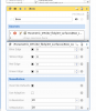
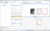
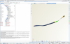
I am trying to connect CAESES to python code via Software connector. The example is to optimize a can.
I already checked the tutorial of connecting to an external software. I followed the tutorial step by step. However, after I put the executable file for python, it just showing pending but no results, then the CAESES will crash or I have to cancel the run manunally to stop it.
I don't know what is the problem, so any advice will help. Thanks a lot in advance.
PS: Path for the executable file: C:/Users/fengy/AppData/Local/Programs/Python/Python310/python.exe
Here is the screenshot of my software connector.
.thumb.png.966b096945c22a0464b02ab5ccc60923.png)
-
Hi Yanxin,
Can you describe what kind of quality you would like to achieve, please?
Regards
Claus
Hi Claus,
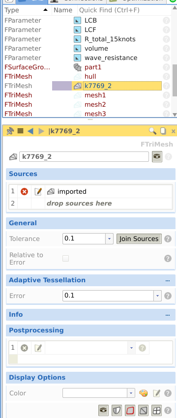
I will explain it with those screen-shots in attachment.
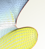
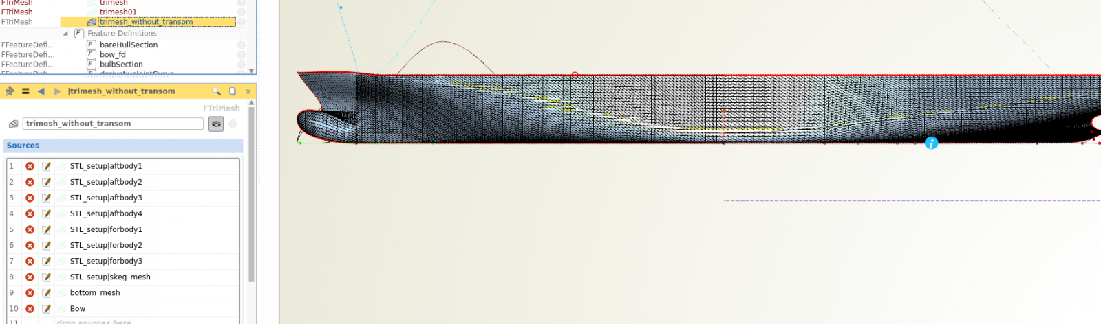
The first one is the goal trimesh I wanted to achieve. It looks clean and nice. And the second screenshot shows how I can edit the trimesh of each surface. The last screenshot is the one piece trimesh of Brep. I am not very sure whether it will effect the simulation phase when I combine GLRankine with CAESES.
Regards,
Yanxin


-
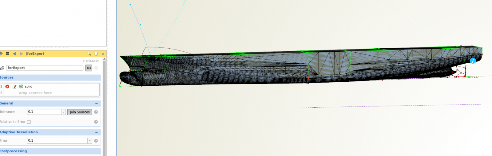
Hi Claus,
thanks for your reply. I checked the trimesh on top of Brep. But the quality of trimesh seems not very well, is there any way to improve the quality of this trimesh?
Coz when I created trimesh directly on surfaces, I could edit the Tessellation of each surface one by one. In this way I could get better trimesh.
Regards,
Yanxin
-
Hi everyone,
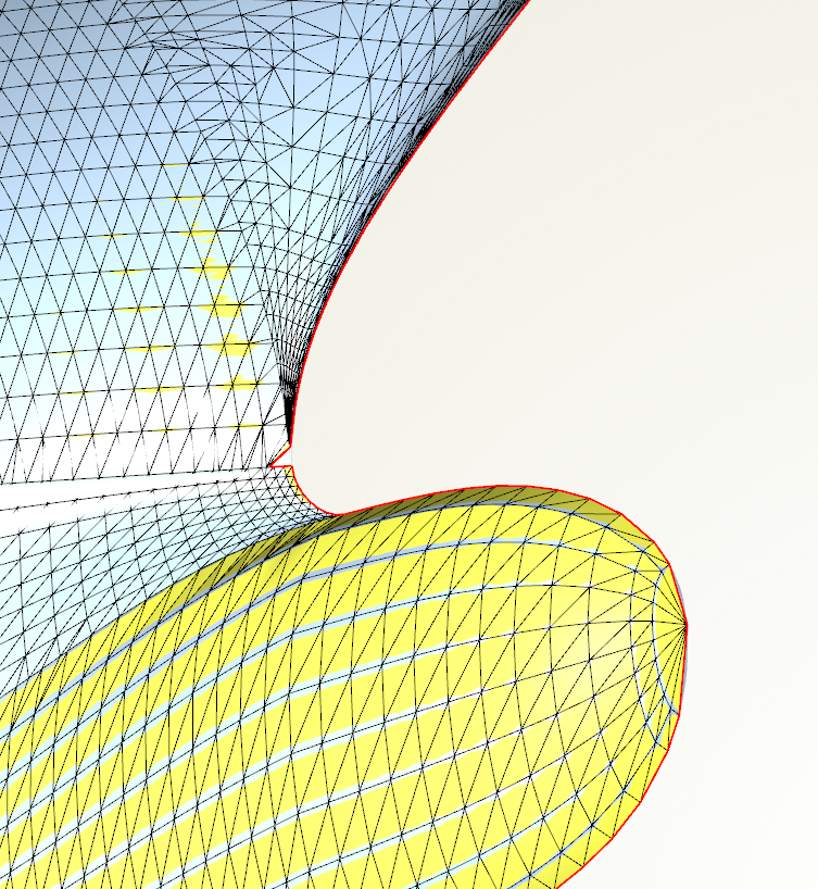
I encountered a problem when I created the trimesh for a containership (DTC).
I already created the parametric ship hull and wanted to export the "stl" file.
But the trimesh I created was not good ennough, there was a gap at the bow part of the ship hull, showed in the attachment.
Is anyone can fix this problem or is anyone has parametric ship hull of DTC ( That would be the best)?
Thanks a lot.
With regards,
Yanxin
-
Hi Yanxin,
Can you please check again whether it works? We have changed the license modules of DUE so that you should now be able to run more designs at the same time.
Cheers
Joerg
Hi Joerg,
it works now, thank you very much! :D
Cheers,
Yanxin
-
Hi Yanxin,
My colleagues will get back to you via email.
Have a great weekend,
Joerg
Hi Joerg,
Could you please kindly remind your colleague to contact me via email? I haven't get any email from your colleagues yet. My email address is fengyanxin0524@gmail.com.
Thanks a lot!
With regards,
Yanxin
-
Hi Yanxin,
My colleagues will get back to you via email.
Have a great weekend,
Joerg
Hi Joerg,
Thanks a lot. Have a nice weekend!
Yanxin
-
I mean could you please update the license to enlarge the limit number of local process.
-
Yeah you are right - I've missed this one. Correct!
Hi Joerg,
could you please enlarge the limit number of my license?
I am using the license of DUE. and here is my license number:
Thanks again!
Yanxin
-
Hi Joerg,
thanks for your detail reply. I did the same set ups. I suppose that my license is limited to just using 4 local process.
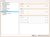
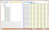
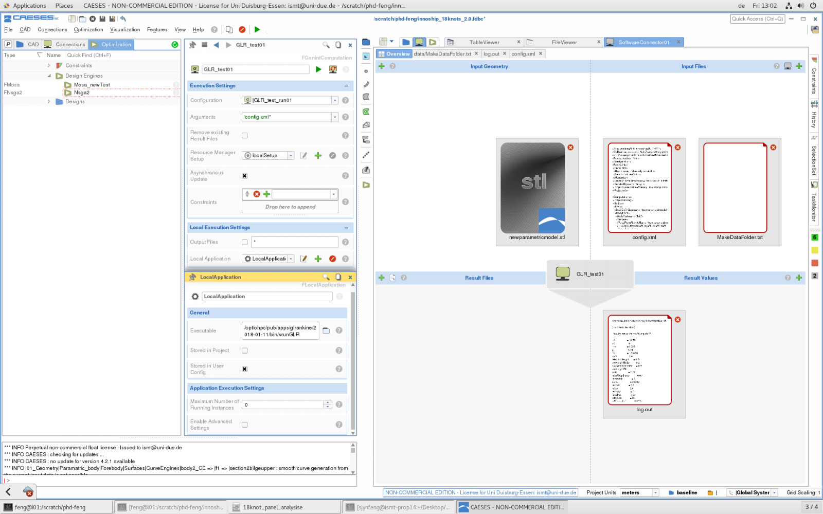
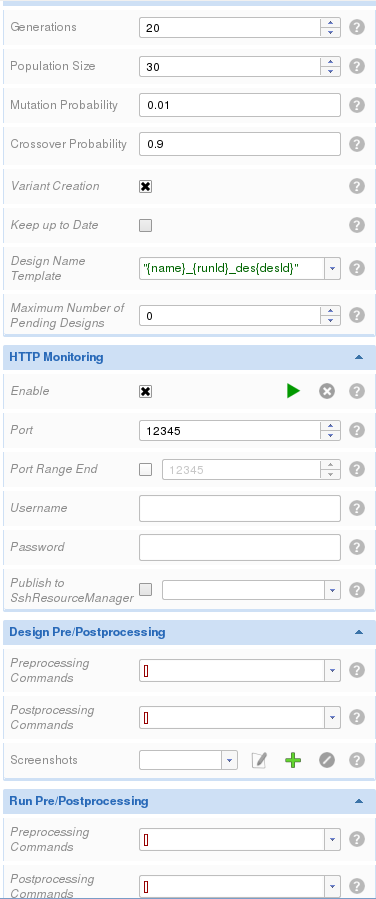
When I am trying to change the number of parallel running Design (step 3): attachment "parallel"
It shows the following reminding:
*** INFO LocalResourceManager : Insufficient license [Your current license state only allows a maximum of 4 parallel running local processes.]
And this is the set up of localapplication: attachment "localapplication"
The set up of NSGA-II: attachment "nsga2"
I hope I described my problem in correct way. Looking forward for any advice. Thanks a lot.
Sincerely,
Yanxin
Hi Yanxin,
There are several settings in CAESES with different effects and purposes:
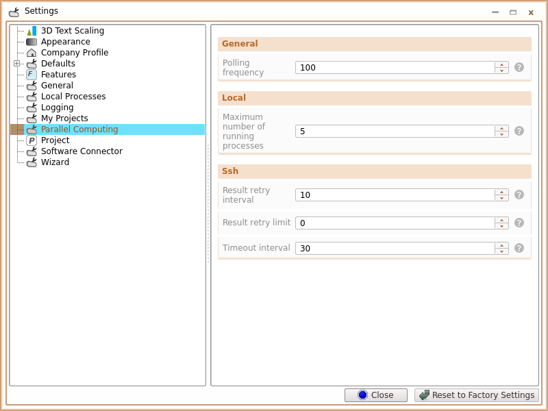
- The total number of parallel running (and also possibly different) applications can be controlled via file > settings:
 settings_global_total_processes.png
 - For each application, you can have an individual setting, e.g. because of license or core limitations etc. settings_local_application.png
- Finally, the design engines also contain a (2nd level, hidden) setting for the number of parallel running designs: settings_design_engine.png
For input 1 and 2, a value of 0 means unlimited (read also the help by clicking on the "?" icon next to the input field). So maybe you can check which setting needs to be adjusted or changed in your case. And, keep in mind the possible license limitations of your external analysis software.
I hope this helps,
Joerg
Hi Joerg,
thanks for your detail reply. I did the same set ups. I suppose that my license is limited to just using 4 local process.
When I am trying to change the number of parallel running Design (step 3)
It shows the following reminding:
*** INFO LocalResourceManager : Insufficient license [Your current license state only allows a maximum of 4 parallel running local processes.]
And this is the set up of localapplication:
The set up of NSGA-II:

I hope I described my problem in correct way. Looking forward for any advice. Thanks a lot.
Sincerely,
Yanxin
- The total number of parallel running (and also possibly different) applications can be controlled via file > settings:
-
Hello everyone,
I had problem when I tried to run optimization with external processes. I chose NSGA-II engine and set up 20 population size and 10 generations. I connected GLRankine with CAESES. I used external process for GLRankine. But when I started running the optimization, only 4 external process could be used.
So my question is, how can I improve the limit of the number of external process?
Any ideas about that? Thanks in advance.
Cheers,
Yanxin
-
Dear Yanxin,
alright then, hope you are making good progress...
Best regards, Heinrich
Hi Heinrich,
it was the range of the design variables lead to the same errors. I got normal results after I changed the lower and upper of the design variables. Thanks a lot!
Best regards,
Yanxin
-
Dear Yanxin,
in this case it is hard to say what causes this behavior. Are you able to reproduce the error. Maybe run the NSGA2 with only 4 designs, delete it from the design folder inside CAESES (click 3 times delete in the following dialogues), re-run it and see weather some no-existing designs get recycled...
Another option might be for you to attach the fdb file so I can take a closer look...
Best regards,
Heinrich
Hi Heinrich,
since now I guess it happened to created the same error because of the config.xml . It was not good enough. I revised the config.xml file and also narrowed the range of the design variables. I will check it again whether sill have the same errors. btw, I did click 3 times delete. So I suppose the problem was caused by the config.xml.
If I still have the same problem, I will write you again. :) Thank you very much!
Best regards,
Yanxin
-
Hi Yanxin,
if you delete a folder within the Designs folder (first Screenshot of yours) and delete everything in the following dialogue - there should be nothing left... However, whenever you start a design engine you will get asked weather you want to take any of your previously generated designs into account "use as result pool". If you don't select any of them they should not get used for the current run and hence you don not need to delete them beforehand.
Best regards,
Heinrich
Hi Heinrich,
I didn't chose the previous designs as result pool. But I still get some previous results, that's why I deleted the whole folder for the previous results. I am also confused how could I still get the previous results. Should I change the name of the new folder more differently?
BR,
Yanxin
-
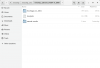
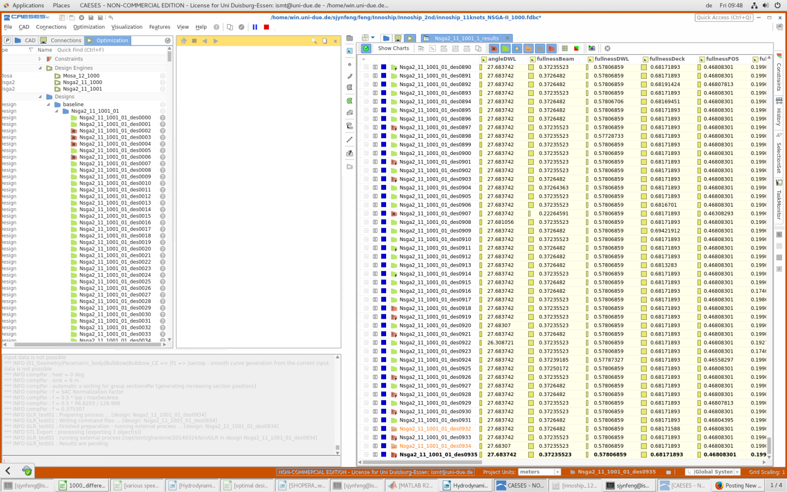
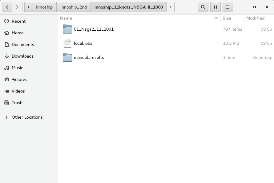
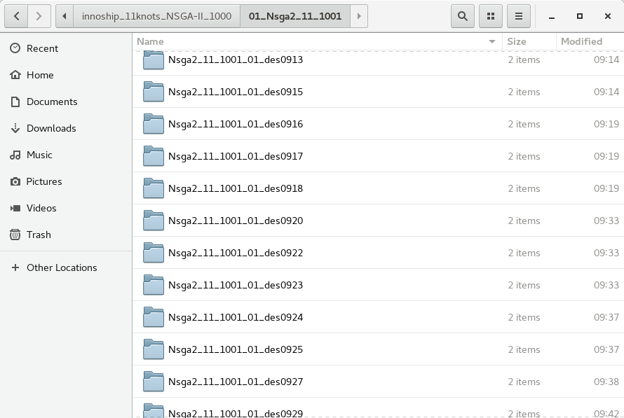
Hi everyone,
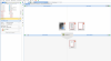
I used NSGA-II optimization engine to optimize a ship hull. At the beginning I got the results of the group "NSGA-II_11_1000", but the results were not good. There were too many errors ,so I deleted this whole folder and also delete the results in the optimization interface. Then I started to run another NSGA-II_11_1001(with changed config.xml), and I didn't run new NSGA-II based on "NSGA-II_1000". How ever, I still got some error results automatically from the old group. I already deleted the old group, so I couldn't find those error results folders in the folder "NSGA-II_11_1001".
In the screenshot, the results with small arrows are the ones from old results. But in the new folder, there are no corresponding folders for those results.
So how could I start an entirely new group without taking the old results from the former groups?
Any idea will be helpful. Thanks a lot!
Best regards,
Yanxin Feng

-
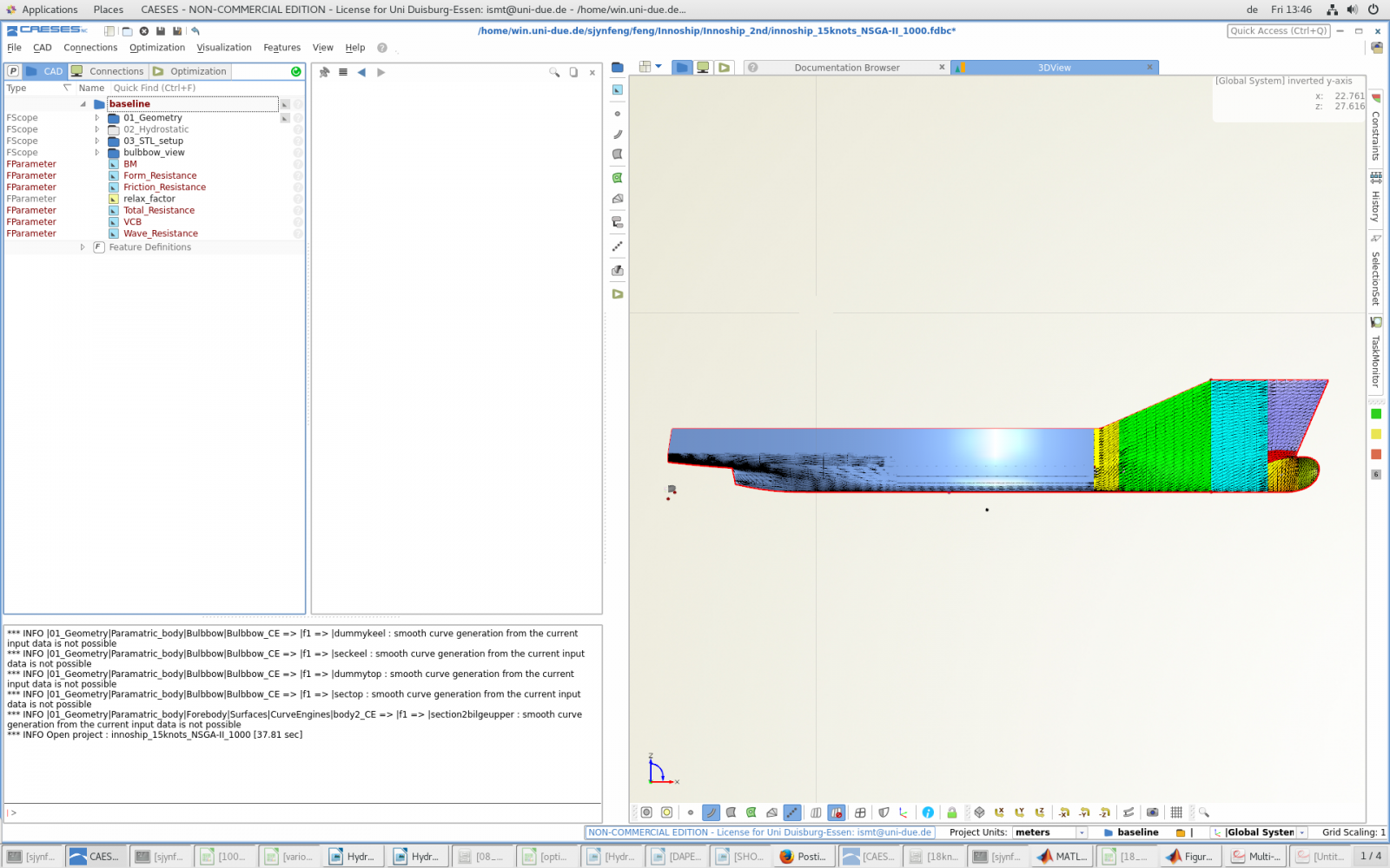
Hi Yanxin,
I have seen such a view when the coordinate values of the geometry are too large. I don't how much it is in your model but I think it would be worth to check it once.
Hi Daehwan,
thanks for your replay. I changed the units back to meters and it is normal now.
-
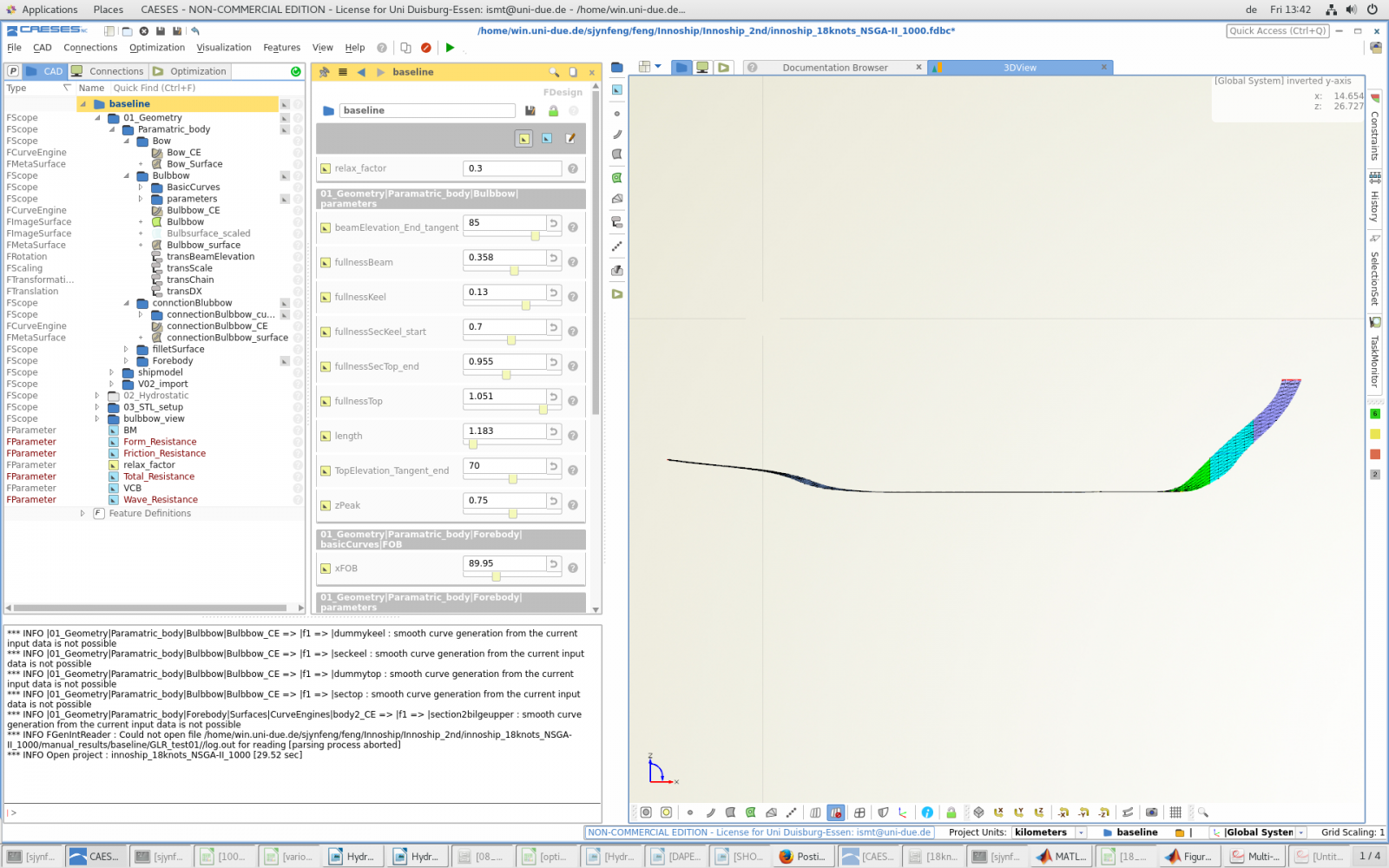
Hi Yanxin,
The project units are set to kilometers. If you set it to meters, it schould be ok.
(to be changed in staus bar -> project units)
Cheers,
Stefan
Hi Stefan,
Thank you so much!! I didn't notice the units. I changed the units back to meters now and everything is normal now.
Cheers,
Yanxin
-
Hi everyone,
I got a really weird problem. When I open this project, I can not see the full model, only a part of it. I didn't make the other parts invisible. When I tried to rotating the model, it can show a little big more, but also not the full model.
The point is, when I opened the other projects, everything is normal. ONLY this project has this weird situation. Is there anybody who got the same problem as me before?
-
Hi Joerg,
yes, this is what I need. Just a simple scale factor is needed! Thank you so much! :)
BR
Yanxin
-
Hi Joerg,
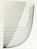
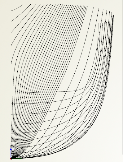
thanks for your reply. It is ok if 2D drawing is not available. I mainly want to know how to get the body plans of the ship hull. I know I can get body plans through setting up section groups.
The problem is, how to put the aftbody and forbody in the same picture but on different side? Because since now I can only get the body plans on one side ( shown in the attachment).
So how to get the body plans as you showed in the screenshot 4?
With regards,
Yanxin
-
Hi Joerg,
Is there any tutorial to show how to realize the 2D drawing of the body plans of the ship model? Especially how to draw the section of ship model with aftbody on the left and forebody on the right side? Just like the fourth attachment in your topic.
Hope you can give me some advice, anything will be helpful.
Thank you very much!
With regards,
Yanxin Feng
-
Hi Yanxin,
I can not really tell you whats going wrong. Can you identify some geometry problems for theses designs? In which format do you export the geometry from CAESES?
best regards
Carsten
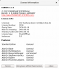
Hi Carsten,
thanks for your reply. Here is the screenshots of the information about the mesh and software connector. Hope this can explain your question. If not please leave me an email so I can send the case to you via email. It is not appropiate to post it in public. Hope you could understand me. Thanks!
Best regards,
Yanxin

-
Hi Yanxin,
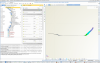
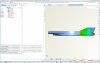
it looks that these extrem CFD results come from a diverged solution. You can check this by going to the result of one of these designs and check if the mesh is ok or not. What application is it?
best regards
Carsten
Hi Carsten,
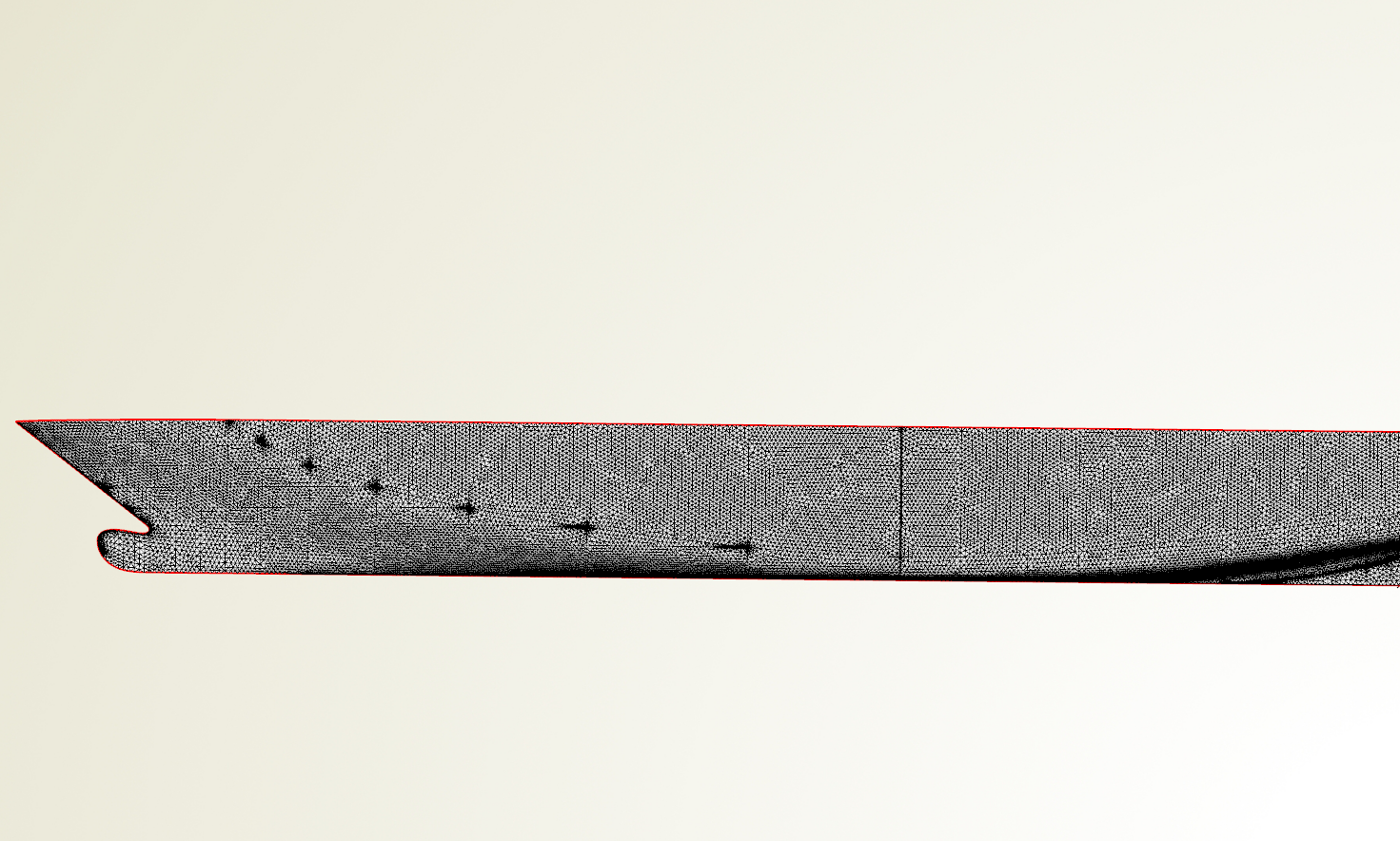
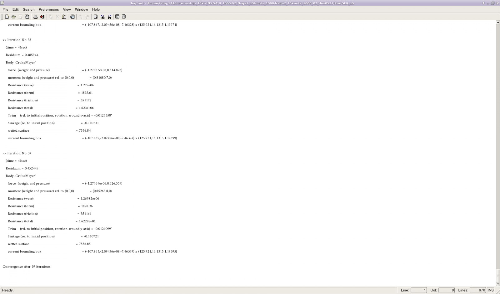
I connected GLRankine with CAESES. I suppose that the mesh of fluent is created automatically in GLRankine. The meshed is imported, rather than created in CAESES. It looks like the screenshot in the attachment.
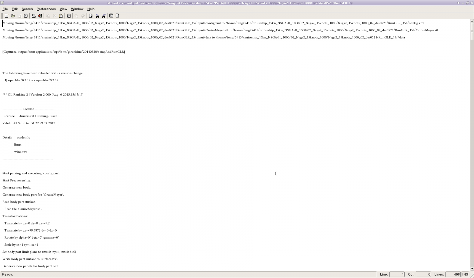
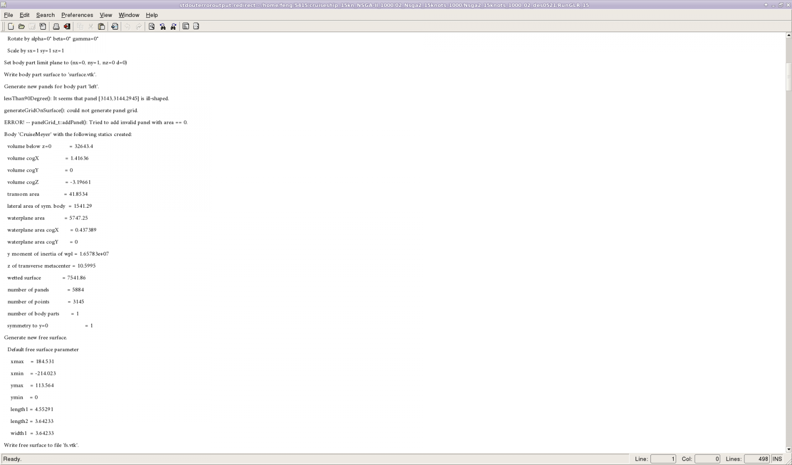
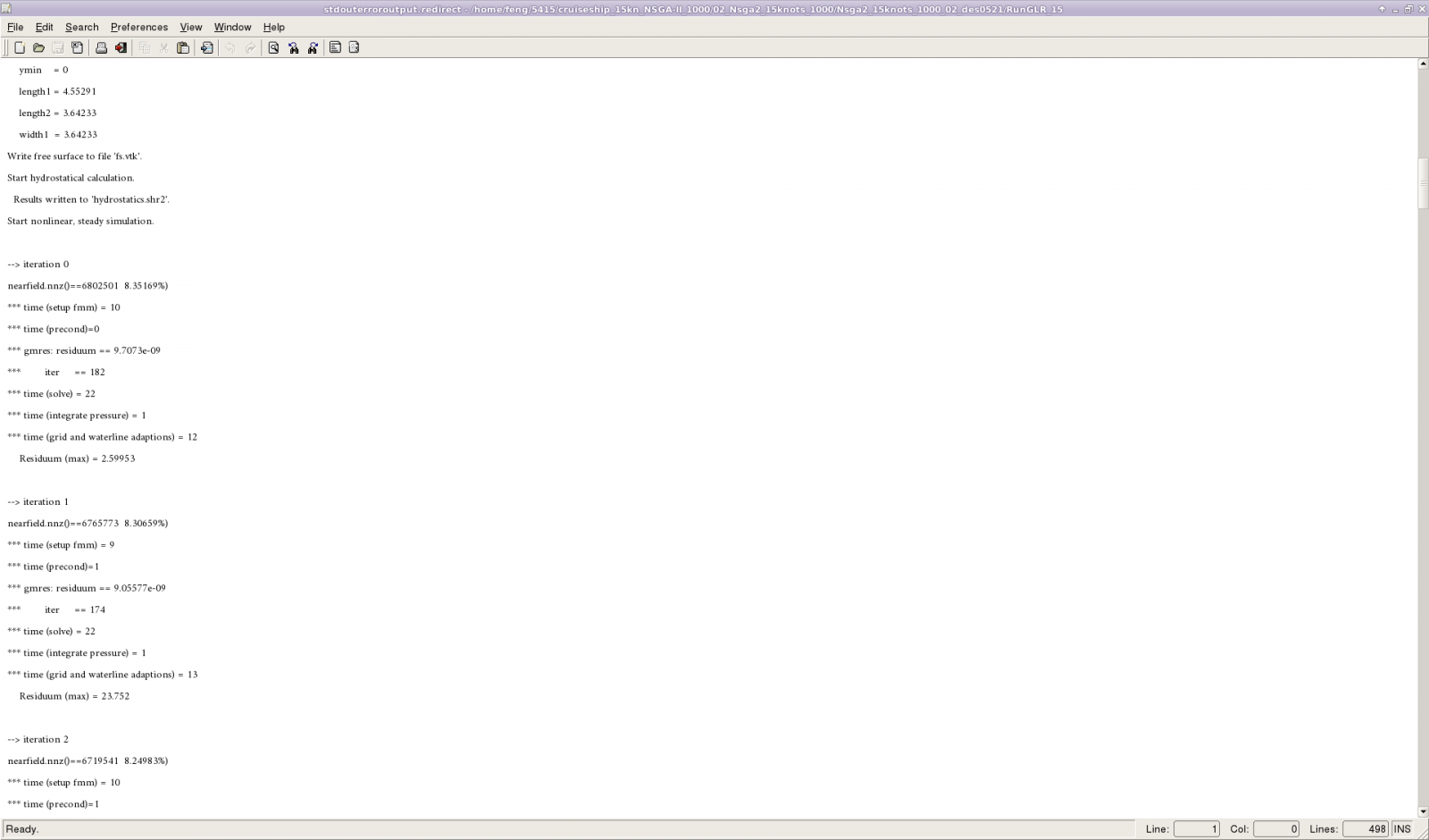
I also checked the stdouterroroutput.redirect of those extreme results. It seems normal but just has several more interations.
I hope you can find sth wrong from the stdouterroroutput.
Thank you so much!
Best regards,
Yanxin


-
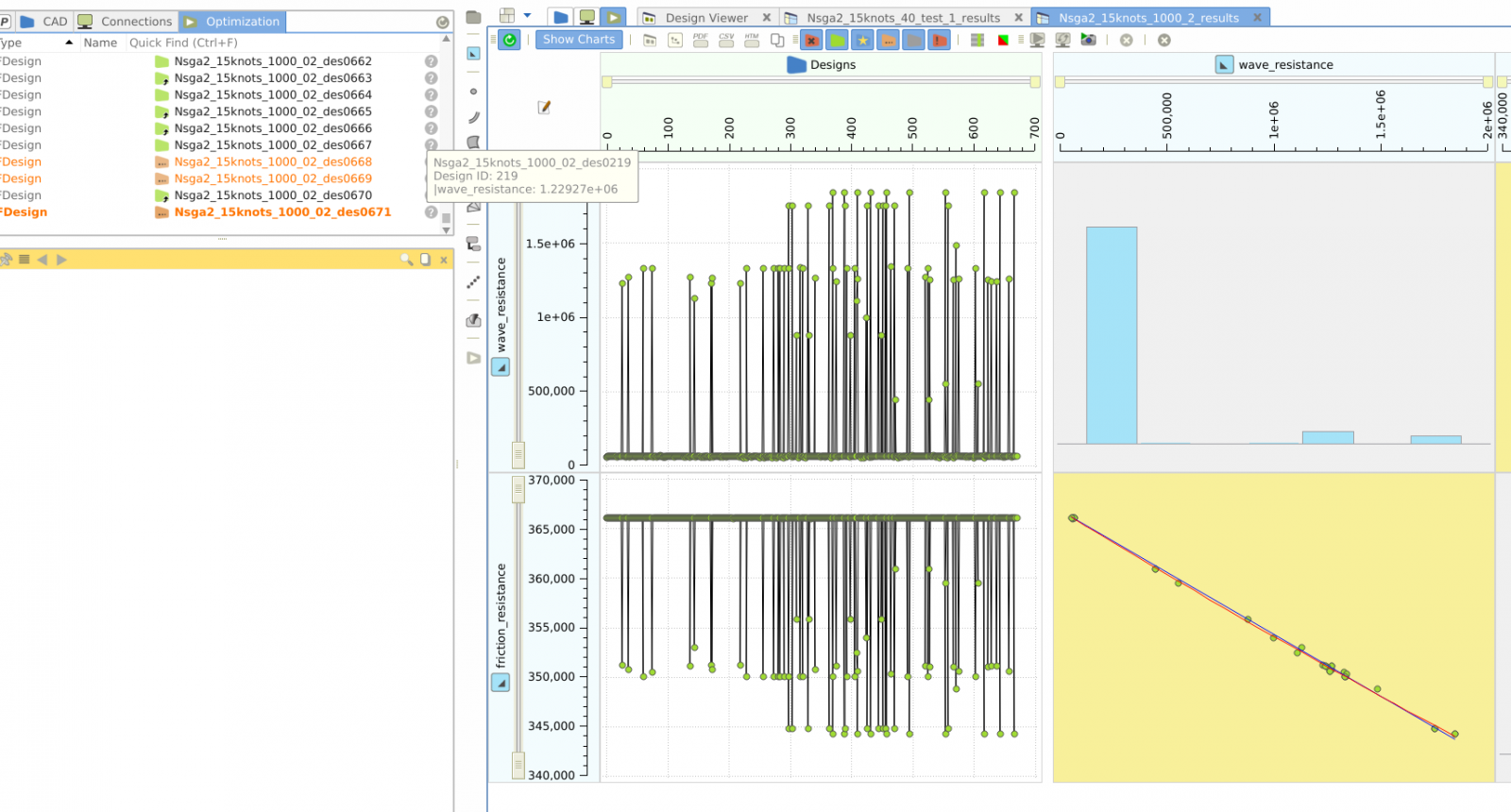
Hi everyone,
I runed a new model in CAESES, but when I was trying to use NSGA-II to get the optimization results. The results showed a lot of extreme values. Is it because that the mesh I did in CAD part was not good enough? Did anyone also have the same problem?
.png.4e92fb426ead931ad12529d2a53f56b3.png)


Software connector "CAESES+python"
in Software Connections
Posted · Report reply
Hi Hedi,
thanks a lot! Problem solved! Now it runs really smooth on my computer. 🙂
Best regards,
Yanxin