


Mr. Carlo Pasquinucci
-
Content Count
32 -
Joined
-
Last visited
Posts posted by Mr. Carlo Pasquinucci
-
-
Hey Chiara,
if you need some more explanations, here there's a simple project with a bulb deformation with surface deltashift and "normal" delta shift.
You can check and use some ideas.
Cheers,
Carlo
-
Hey together,
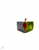
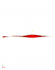
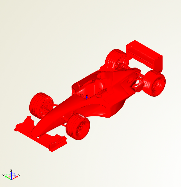
it were nice to try to deforme a f1 car in just few hours.
It is possible using Free Form Deformation, starting with a STL file for an original car.
Free different examples are given using two different custom BSpline Volume.
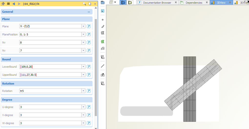
The first volume is a rectangular standard volume (first photo in blue), customized with the possibility to rotate it (first photo in red).
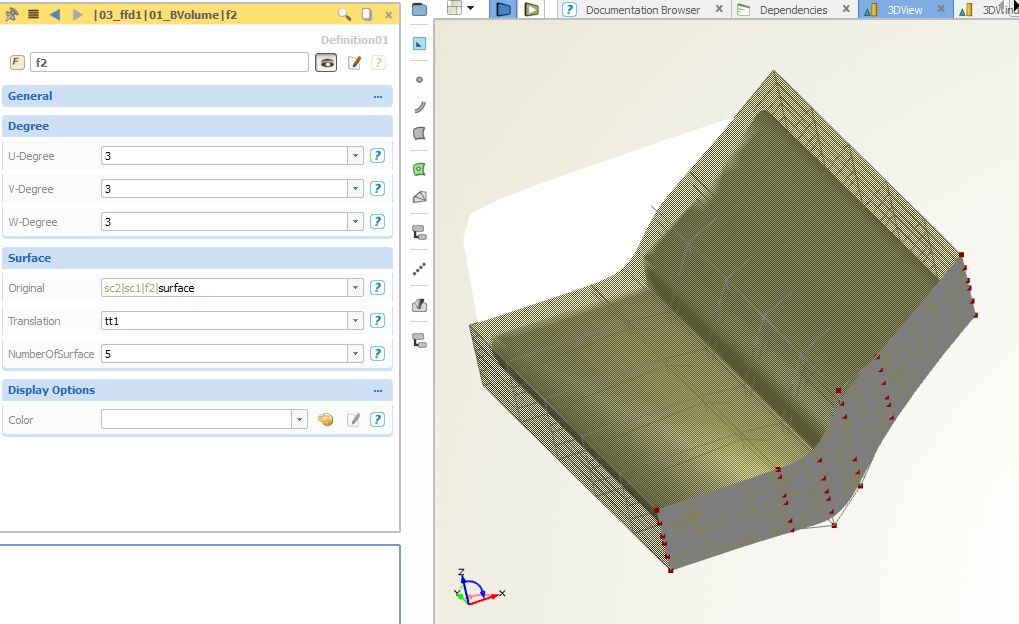
The second is a more complex. You have to design your initial BSpline Surface and later the volume is created on n parallel surfaces.
The two features are also given.
All the project, with also the creation of the Gifs took around 6 hours, instead of different days of a standard full parametric design.


-
Hey Hamidreza,
I tink that you want to run an internal optimization, corretly?
So, an optimization inside an optimization, correctly?
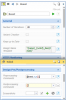
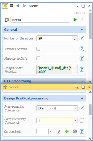
If you can, I suggest you to setup the internal optimization outside of the feature and the run inside the design preprocessing, like in the picture.
The Brent internal optimization is run for each evaluation of the Sobol.
In the Brent you have to keep away the tick of Variant Creator.
On the other hand, if you can do this, there's a fast solution of your problem.
You have just to crate another parameter in which you put the value of the parameter of the feature.
I attach a picture to explain better.
Can you try this solution?
Cheers,
Carlo
-
Hey Leja,
it was not so clear.
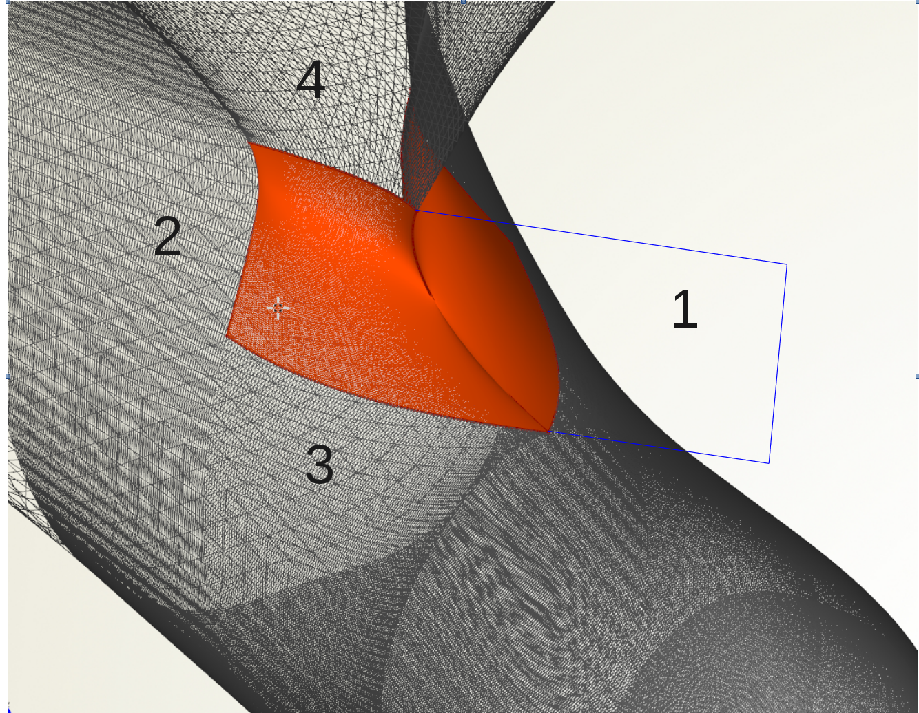
I attache a picture.
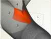
I think the best idea is to create surface like the number 1, then create an image of the number 1 and the number2 with a domain [0,0.8] in "z"direction (I don't know if it is u o w direction, sorry)
Then fillet this two image surface.
Then fillet the result with the number 3
and then fillet with the number 4
Or maybe you can work with two or more more little surfaces.
If you can attach the project, maybe only that part, can be easily for us to help you.
Or you can send via email also with password.
Thankyou and have a good job
Carlo
-
Hello Lenja.
I think I have two ideas..
First, I suggest you to create a planar surface in the y-plane.
Then, the first idea is a little complex. You have to create a metasurface. You can fin an idea in the sample "Fillet Surface". That is bewtween two surface, but you can modify it in order to be fillet also with the other two surface.
The second idea is to fillet the vertical surfaces, then fillet this fillet surface with one orizzontal, then with the other planar.
Maybe it would be better to reduce a little the domain using an image surface with domain [0,0.8].
Can you try this second idea?
If it is not clear, just re-answer.
Cheers.
Carlo

-
Hey,
sometimes you have as objective function not one value of the results file, but you want to have a derived value of some iterations.
CAESES can evaluate directly the mean of some values in a column in the results file, but maybe you need the max (or the min, or the ratio max/min..or whatever) value of the last n- iterations.
Or, you would like to have a result interpolating some results in the output file.
If you need, I create this feature that do this job.
You need to run it in the design postprocessing.
I hope that can be useful,
Cheers and good results,
Carlo
-
Hey,
I prepared one similar project, in which a ship is first deformed using the Lackenby deformation and later the draft is changed in order to have the same displacement as the first ship, using a Brent internal optimization.
The equality of the two displacement is checked by an equality constraint. If the displacement is not reach, you can avoid the calculation of the external software.
Cheers,
Carlo
-
Hi Johannes,
CAESES try always to find the minimum.
The suggest workaround from Stefan in correct. Theoretically is possible to change the input file for Dakota to force to find the max and not the min. I really suggest you to use the Stefan method if you are not expert.
Otherwise, you can write sense max , in the response field in the Dakota template.
Cheers,
Carlo
-
Hey Bugra,
I don't really understand if you want to assign a dimension on an angle or if you want to have the dimension of the angle.
Theoretically, the linear and angle dimensions are only for visualization, so, I suggest you to find another way.
If you want, you can create a angle dimension using this sintax:
dim1.setStart([-3,0,0])
dim1.setPosition([0,0,0])
dim1.setAngle(angle)
dim1.setEnd([0,0,4])you need to assign also an end, but the end has no influence on the angle.
But, later, you can't have the angle as double. There's no dim1.getangle(), because the dimensions are only for visualization.
But you can easily calculate the angle using the tangent method.
You can calculate the tangent of the two segments and than use the command atan()
Otherwise, you can use directly the command atan2(point1, point2), that gives you the angular dimension between the two points.
Attention that the value is returned in degree. If you want the radiant, you have to use atan2(point1,point2,false).
I think that now you can have the value of the angle in a very fast way.
If you have problem, please ask.
Cherres,
Carlo
-
Hi Bodo,
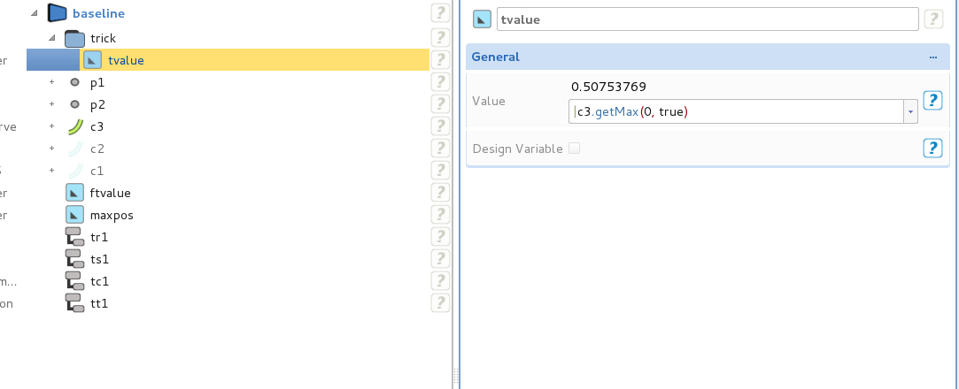
I had also the same problem, but there's a very simple way to solve it.
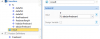
When you ask NACACurve.getMax(0) , you have in return the x position of the max.
If you want the t parameter, you can just ask NACACurve.getMax(0,true) and now you have the position in t coordinate of the max. See the screenshot.
The problem is that for a numerical error, the command ft(0,xpos) can't find a point in the max (and in the min) position if you give the x-position and so give you the position on t=1.
If you reduce a little that number, like Matthias suggested, this command has no problem.
I will report this error to the developer.
Thankyou very much,
Carlo
-
Hi Daniel,
do you open the file in Windows?
Beacuse, the problem is that I created in Linunx and so in WIndows the STL in Windows in empty.
But, you can use with the different examples that you can find in the samples folder.
Cheers,
Carlo
-
-
Hey Hamid,
I have the also your problem.
I would like to develop a new feature.
I think that maybe next week can be finish.
I will upload here later.
Cheers,
Carlo
-
Hi Jeff,
if you need to export as.txt file, here there's a sample how to do this:
The idea is to put all your values and all the name of the values in a objectlist and the write them with writeline(string)
//
objectlist text_coef()
objectlist values_coef()
double los_los(los/(los_ship))
text_coef.add("L/LOS")
values_coef.add(los_los)
double cb(volume/(los*beam*draft))
text_coef.add("CB")
values_coef.add(cb)
double b_t(beam/draft)
text_coef.add("b/t")
values_coef.add(b_t)
double cobx_los(cob:x/los)
text_coef.add("XCB/LOS")
values_coef.add(cobx_los)
//
file.openReadWrite()
file.readAll()
loop(values.getSize())
file.writeLine(text.at($$i).castto(fstring)+" "+values.at($$i).castto(fdouble).toString())
endloop
loop(values_coef.getSize())
file.writeLine(text_coef.at($$i).castto(fstring)+" "+values_coef.at($$i).castto(fdouble).toString())
endloop
file.close()Best regards,
Carlo
-
Hey,
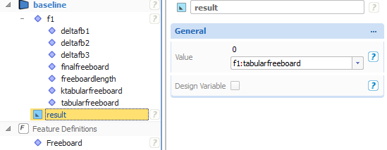
if you want, I created a feature that calcolates an approximated freeboard, that is quite near the real one.
You can use as input the geometry of the ship or directly the main data of the ship.
As output, you have the tabular freeboard and the correction for the cb, for the sovrastructure, for the L/D dimensions and for the sheer.
I tested it with some ships, and the results are very similar.
I attached the project.
I hope that you can use it in the future.
Cheers,
Carlo
-
With the version 4.0, we are implemented the use of the free form deformation.
It’s a very powerful method, but sometimes can be a little hard to understand which can be the best set up of the box, per example, the number of sections in u,v,w,-direction, and sometimes can be very tedious check an idea, reset up the box, reselect the points, and so on..
This can be a big problem if you want to change directly from one algorithm the setup of the box and not only the values of the deformation.
For this purpose, I created this feature that applies a deformation, independent of the number of sections in u,v,w-directions.
(Take care that the number of section must be an integer and the algorithm in Caeses for now can’t use integer, but we are working on this problem).
You have to think a deformation and then you have to write in feature the logic of this deformation and the points are automatic selected.
For example, I would like to move one section 3 meter in x and the next one -3 meter in x, independent of I have 2,4,6,8,10….etc..etc..sections.
You can also set up the logic that you want. See the attached gif for two examples. You can take a look also on the project.
(Free form deformation is only available on commercial license)
I hope that this can help you to improve the possibility of the ffd in optimization projects.
Cheers,
Carlo
-
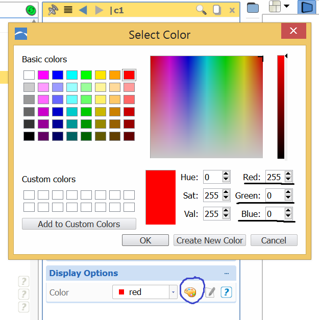
Hello,
sometimes in a feature you have lots of objects and you would like to color them in order identify them better.
How to do this?
You have to write in the feature:
.....
name.setcolor(value of red, value of green, value of blue)
......
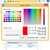
How to know which numbers you have to put inside?
You can go to display options of an existing object, then click on the palette and you can find the values of red, green and blue, in order to write correct numbers in the feature.
So, later, you can easily visualize the different objects in the feature.
Cheers,
Carlo
-
Hello,
I created these features with witch you can entry in the results of your run and make some statistical analysis, like the linear regression between two parameters and the correlation matrix between the design variables and the objective functions.
There's also a feature that calculates automatic which parameter has more influence and which has lee influence on the objective function.
This can help you to understand which parameters you can remove from your optimization.
Cheers,
Carlo
-
 1
1
-
-
Hey Campus,
if you want, I created a feature in order to go inside the designs and store the parameter values after a run.
If you want, you can export or plot the values of the parameters.
-
Hello Stefan,
I solved!
You need to put these lines:
"foreach( fdesign des : designs)
fdesign des2(des)
fstring name(des2.getName())
if(name.startsWith(runname))
............
endif
endforand the run name must be like runname_number_des, in order to avoid the baseline and other designs.
Cheers,
Carlo
-
Hi Svetlozar,
in Caeses it's possible to export NURBS surface, if you don't care about the polygon of control, but they are Nurbs.
After your modellation, you have to select each Imagesurface and create a Nurbs from it. Then, you can export as Nurbs and also as 3dm. But the poligon of control is not more the original one (it has more points).
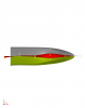
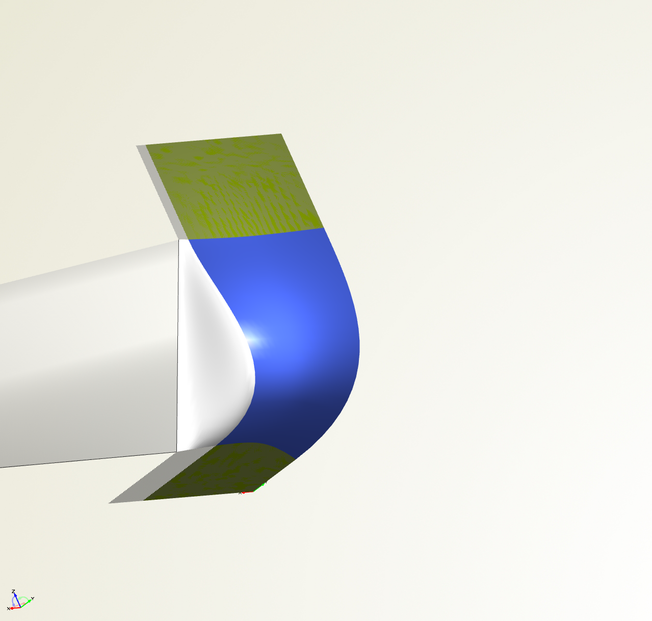
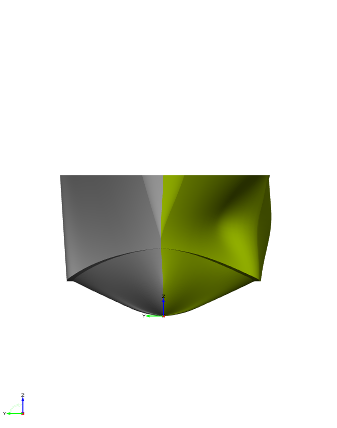
If you use the SurfaceDeltaShift or Deltashift or other Shift function, the total surface remain watertight (if the original are watertight),because the same transformation is applied to each surface. You have to keep attention only on the keel
In order to deform the geometry using the pressure field, my idea is to use SurfaceDeltaShift with a Bspline surface and the move its points in y direction in according to the pressure field.
If you have an example outpfile from Star, I can explain how to do.
In the attache picture, the grey surfaces are the original ones, the green, the deformed, the red the deforming bsplinsurface
and in gold the control points that you have to link to the Star file.
Cheers,
Carlo

-
Hi Nevkov,
if I good understood, you want to coupling Caeses, Rhino, StarCCM+.
The idea is to start from Rhino, go to Caeses, modify the geometry in Caeses, export in Star, reimport in Rhino, modify in Rhino.
In Caeses you can easily import your Iges file from Rhino as Nurbs, deform as you want and then I created a feature that approximate the deformed surface to a bsplinesurface that you can export in Star and in Rhino, but not always it works good and you have to customize for your geometry.
It's very complex and I suggest to use another strategy.
Sorry, but I don't understand why you need to use also Rhyno.
Another question: the pressure in Star are exported in a text file?
Thankyou
Carlo
-
Hi Neykov,
I think that you can easily deform your geometry applying the Free Form Deformation in Caeses directly from your import geometry.
With Free Form Deformation you don't need to remodel the geometry, but you can easily work directly on the imported Iges.
I was thought for this kind of problems.
If you need some ideas, you can share me (through email) your geometry.
I'm thinking a solution that can be useful for you.
Cheers,
Carlo
-
Hi Stefan,
thankyou very much for this feature.
The main problem is that it calculate the best design of all the created designs and not only for current optimization.
It´s possible to avoid this problem? (Without delete all the previous optimization?)
Thanks,
Carlo


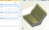
Bulb Deformation using Delta Shift and Surface Delta Shift
in Variation & Optimization
Posted · Report reply
Hey Guys,
I prepared a simple example of a Bulb Deformation using Delta Shift and Surface Delta Shift starting on an original STL file.
Two easy tricks:
_ The creation of sections in Y-Direction on the surface for the Surface Delta Shift, that can help you to understand the deformation amount.
_ The split in two different ImageTrimesh, in oder to apply the Delta Shift only on the lower Trimesh.
It is not the most robust way, but it is the faster and very easy to understand.
I hope that this example can help you!
Cheers,
Carlo
ExampleForForum.fdbc