


Willy Maschen
-
Content Count
22 -
Joined
-
Last visited
Posts posted by Willy Maschen
-
-
Hallo Mr. Miao,
to get a parametric model in CAESES you have to rebuild your tire import (alternatively you can use Free Form Deformation, but that is not available in the Free version. Also i think it's not a good solution in this case).
To get an idea how it could be done i would recommend you to do the "Parametric Contour" tutorial. Then create a tire contour and use a "Sweep Surface" to create it.
Best Regards
Willy
-
Hallo Takaya,
now that you have the camber lines you will need to rebuild them and use the meridional camber provided in CAESES.
If you open the "Documentation Browser" in CAESES (it is next to the 3D Window tab) you can select tutorials and will find 2 tutorials under "Content of Blade Design" named "Impeller Design" and "Meridional Camber" that will teach you how you can do it.
I hope this helps. If you have more questions feel free to ask.
Greetings
Willy
-
Hallo,
i would recommend you to create a surface for the deck. Then create a stl of this one side. Create an image trimesh of the that side and use a scaling transformation, that is set to [1,-1,1]. This will mirror your half onto the other side.
Then you can put both sides into a trimesh and you have the complete hull (should be watertight at that point). This will be good when you import it to the CFD, as your part will bigger than the domain and not cause trouble when you use e.g. subtractoin options.
Greetings
Willy
-
Hey,
CAESES itself is not capable of doing CFD, so what you have to do is:
1. Choose a CFD software (e.g. OpenFOAM, Starccm+, CFX, Shipflow ... as long as it runs in batchmode)
2. Set up a computation for calm water resistance there
3. Connect it to CAESES via the Software connector.
For the Connection you can find a few tutorials, as well as helpful forum posts.
Also you are ofcause welcome to ask questions if you get stuck.
Greetings
Willy
-
Hey Mohamed,
CAESES can handle a variety of formats. To see all of them just open CAESES and select the tab "File > import > .." in the top bar. I personally like to use the stl format when working with StarCCM+.
The workflow you described would work, but the problem is, that if you use an imported file from another modeling software you will only be able to use Free Form Deformation with it.
The other way would be to rebuild the propeller in CAESES itself (There is a tutorial in the documentation browser, that shows you how to build single blade and from there it is a rather small step to the full propeller).
You can of cause also look into the samples and just select a propeller from there, or there are some forum posts (also with complete propellers) that you can find here: https://www.caeses.com/forum/index.php?/topic/257-meta-thread-marine-propellers/
Greetings
Willy
-
Hey Hannes,
your setup looks fine. For me it is a little hard to recreate your problem though, because the workflow without nushallo is to create a seperated "color mapping" object and that works fine.
Is it possible to post your project here so i can have a better look at what it might be (as i don't have nushallo to create solutions).
If you don't want to post it in public you could also sent it to me via mail.
Greetings
Willy
-
Hey Azlina,
it is possible to export your CAESES model as an .iges or an .stl file. In an automated setup you can do that as described in the tutorials about software connection.
If it is just your current design you can select it and then go to "File > Export > " in the top left bar.
Be aware, that if you want to export as an .stl you need to take your surface model and put the surfaces into a trimesh object.
A good tutorial to see how this works is the "Postprocessing" one.
ANSYS should be able to handle both of these formats.
If you have any further questions feel free to ask.
Greetings
Willy
-
Hallo Azlina,
to see what kind of licens you have just click the "Help" tab in the bar on the top left. There select "About".
A Naca Profile can be created via "CAD > Curves > Naca-4DS Curve" or if you dont want a 4DS Profile you can select the Naca Curve.
To get started with CAESES i would recomend you do some tutorials first. They can be found in the documentation browser under tutorials and visit our youtube channel:
https://www.youtube.com/user/FRIENDSHIPSYSTEMS
Greetings
Willy
-
Hi again,
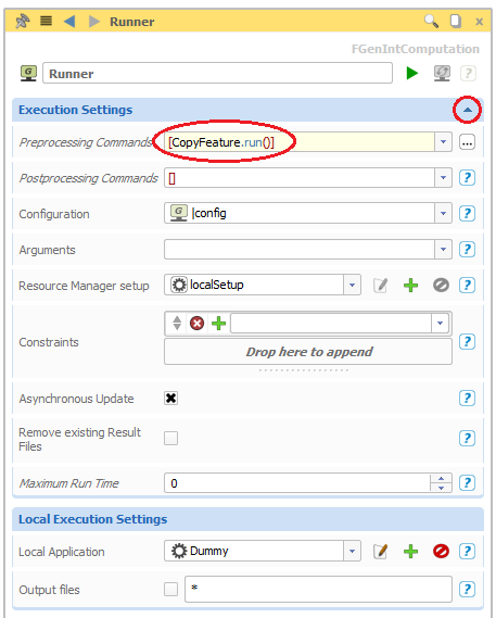
I think the problem is, that when doing the runs you didn't import a ".csv" file as you can see in your software connector. If you deleted the results automaticly after a run I fear you cant recover them. But if you have the ".csv" files still somewhere you can read them into CAESES through a little trick. That requiers you to run the Sobol again with a dummy as executable (e.g.) Editor or Notepad. Then you can write a feature, that copys the result files from where they are right now to the location of the new "dummy" Sobol (this time the .csv needs to be in the software connector under result values too). This should solve the Problem.
The feature definition would look something like this:
cp(<directory/>+getCurrentDesign().getName()+"/OldSobolName or Directory with the csv", getDesignDir()+"/NewSobolComputationName")
Then create the feature and select it to run infront of the Computation (See Screenshot)
Greetings
Willy

-
Hey Yanxin,
first you should check if the resuslts are still on your hard drive. So in the folder where your project is stored there should be a folder with the same name as your project.
E.g. : If your project is named my.fdb there should be a folder called my.
In this folder there should be another folder with the name of the Optimization algorithem you used e.g. 01_Sobol.
Is that the case for you?
Greetings Willy
-
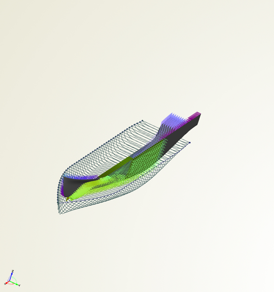
Hey Shahriar,
so what happens to create the bow you sweep an fspline along the profile lines.
The upper and tan discribes the angle the bow will have at top and the lower tan will do the same for the bottom part of the bow.
The fullness is influencing the volume the bow will have at the top part.
I tried to put all this into the picture attached.
Hope this helps you
Greetings
Willy
-
Hey Victor,
it is possible to put lables in your project. You can find the under the tab "Visualization" in the top bar.
Greetings
Willy
-
Hey Patrick,
i think a good solution would be to create a "Center Plane Curve" that gives the bottom conture of your canoe and finish the ends with the "Smooth Joint to Stem" feature. This procedure is explained well in the "Fast Monohull" tutorial, so i would suggest you have a look at that.
Greetings Willy
-
Hello,
any example would help :)
Greetings
Willy
-
Hey,
i think this can be done more automated in CAESES.
Would it be possible that you give us a sample file so i can have a look at it?
Greetings
Willy
-
Hallo Bodo,
the ".castto()" changes the object type. So for example i can change the type of object "A" to a solid when typing "A.casttod(fsolid)".
But for what you want to do you need to set the FEntityGroup as an Argument.
Attached you can find a feature that will need an FentityGroup as input and the return a vector that is the sum of all COG of the solids in the group.
Greetings
Willy
-
Hallo Mr. Yeonuk Kang,
to be able to use the Dakota engine in CAESES an extra licence pack is needed.
Greetings
Willy
-
Hallo Utako,
what happens is, that the NURBS curves show you how the certin variables change opther the length. So for example the deck-y curve represents how the y position of the deck is changing.
I would recommend you to do the "Yacht Hull" tutorial. It will help understanding the modeling i think.
Greetings Willy
-
Hey,
I'am not completly sure what you mean by UV-Revolution but a way to change the diraction of U or V is to create an image surface and change the doman fom [0,1] to [1,0].
The exclamation marks don't necesserily have to cause trouble when you creat a trimesh but it is very likely.
Greetings,
Willy
-
Hallo Ms. Feng,
Unfortunatly it is only possible to change the UV-Orientation of point based surfaces, as you said about your B-spline surfaces.
Maybe you can try to close the openings with fillet surfaces.
Greetings
Willy
-
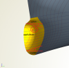
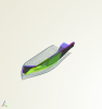
Hey Maurizio,
the problem is actually the orientation of your surfaces (see the attached picture. To visualize normals just expand the display options of the surface and set the flag for normals/(scale).
This problem can be fixed by creating imagesurfaces and swapping the domain. I did this in the attached project.
-
 1
1
-

2d blade profile to follow arbitray curve while remaining in specified plane
in General Modeling
Posted · Report reply
Hey Brami,
to solve this problem you can use a translation instead of a sweep transformation. The key is to use the .getpos() command onto the curve. If you have a setup like in the picture it should work just fine.
As an input for the getpos() i used a parameter that goes from 0 to 1.
Hope this is what you needed, if not feel free to ask again.
Greetings
Willy