


Mr. Simon Broenstrup
-
Content Count
22 -
Joined
-
Last visited
Posts posted by Mr. Simon Broenstrup
-
-
Hi,
sorry I uploaded the wrong file.
The second way does not really give you two different layers, at least internally there is no surface between the two layers. That is just the ways Breps work within CAESES and as I said depending on what you want to do with your CAD Model after designing it that might be suitable for you. For example if you wanted to do a CFD computation the internal model would not really madder.
But again the way you have done it, is the only way how to have two separate layers.
If you have any more questions just let me know.
Cheers,
Simon
-
Hi Bram,
in the first step you are trying to connect two closed BReps (AISFree and BSFree), but since the initial BReps are already closed it is causing your problem later on. If you would leave one of the Breps open and try to connect them, you would see that it will not work. So to solve this issue there are two options:
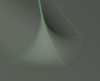
I would recommend either having the two layers of the support plate as two separate Breps, which both can get the bolt hole by using the boolean operation difference. Or the second way is, to create the two layer in one BRep with two following extrude edges to plane operations and cut the bolt holes out after that.
I attached the second option as an example. Depending what you want to do with your project after you have set it up (CFD, FEM) one way might be more suitable than the other.
Cheers,
Simon
-
Hi Chris,
I think there are two valid options how you can work around this problem without waiting for the 4.2 update.
The first thing which will help you, to have a more stable model is, to change the splitting line of the BRep to the top instead of one of the sides:
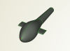
I have done this by changing the start and end angle of your input sections from 0 and 360 to 90 and 450.
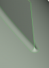
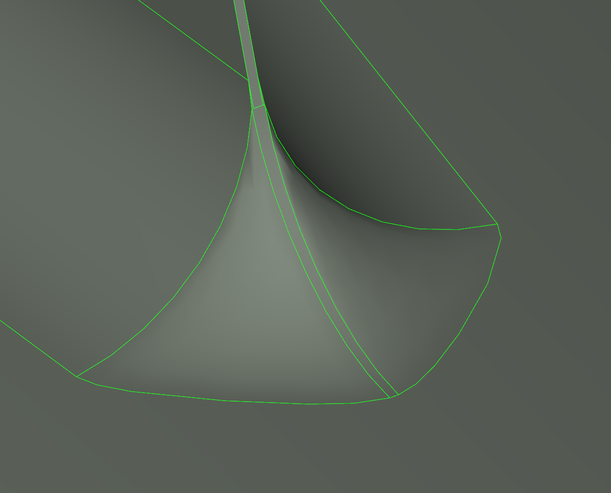
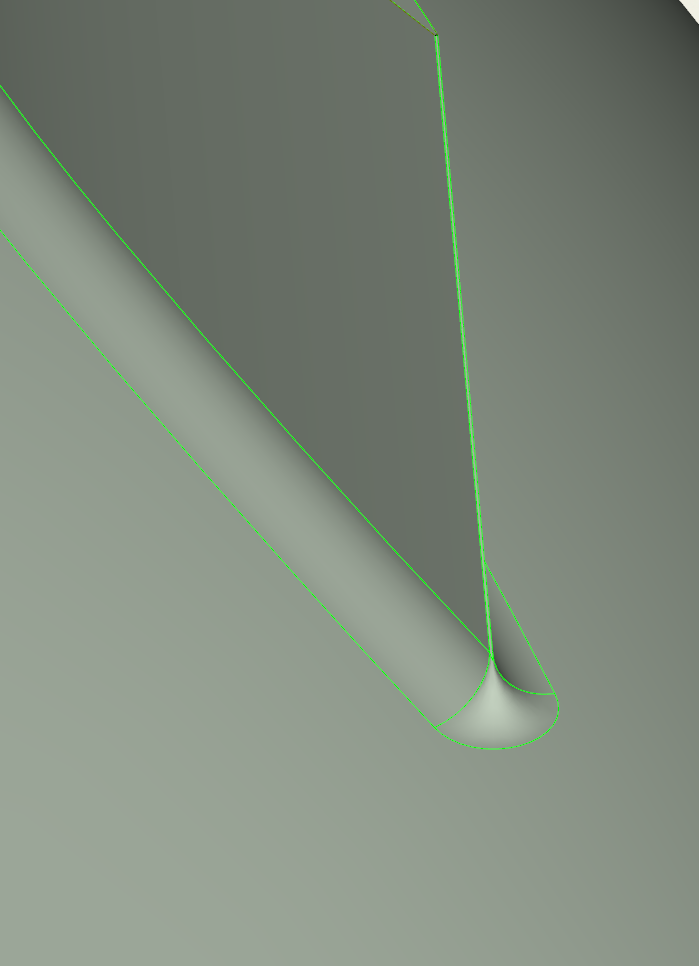
Another cause of problems is the way your trailing edge is shaped. The sharp edge at the end makes it hard for the fillet feature to find a correct fillet.
This could be solved by designing a trailing edge with a circular fillet or by creating the fillet between the main part of the plane and the wing manually (but this solution is a bit more complicated)
With the circular fillet as the trailing edge it looks much smoother.
You can find all the cahnges in the attached file.
Cheers,
Simon
-
Hi Chris,
the boolean operation only works with closed BReps, therefore you can use the close-planar holes operation.
I also added the a radius at the root.
Cheers,
Simon
-
HI Chris,
there are some good tutorials within CAESES that could really help you.
I think a suitable way of designing your sailplane would be to create the main body as a sweep surface. Therefore look at the tutorials, Content of General Modeling > Parametric Contour and Content of Meta Surface > Sweep Transformation.
This way you should be able, to create a parametric profile and create a surface by sweeping it along a patch, which is adjustable in the z-axis.
For the connection of the wing root you could create a small wing (see tutorial First Modeling Steps) and connect it to the main body by using BReps. This is explained further in the tutorial Introduction to BReps. The side rudder can be designed and connected to the body in the same way.
I hope this gives you a good idea and brings you on the right track.
Cheers,
Simon
-
Hi Ben,
sorry, I am not an expert on the Ka-Series myself.
It might be possible, that the ordinates of the points need to be added, if I do that a good looking profile is the result, but I do not know if that is the correct way and I could not find any detailed in information in the literature.
I am pretty sure the face from 0.5 on is a straight line, because it is similar for other series propellers. I would also assume for the profiles of 0.7 and higher the maximum thickness is at half of the chord length, as it is shown in the images of the sections.
If you have further questions on how to set it up in Caeses just let me know.
Cheers,
Simon
-
Hi Ben,
I do not have a KA-series propeller I can give you. But we are working on a wageningen B-series prop at the moment and looking at the data of the KA-series, the design process should be similar.
So I would recommend you follow these steps:
1) create the points for all the profiles (from 0.2 r/R to 1.0 r/R) from the data. Out of these points create an interpolation curve for each section
2) Use a skinning (lofted surface), with all the sections created in step one, to create the main part of the blade
--> These two steps are best done in a feature, for more information have a look at the tutorials within CAESES regarding features or look at this blog post. It contains a great guide regarding feature programming.
3) Create the tip of the blade by using a separate feature
4) Create the fillet between the hub and the blade. Best done by using Breps ( Edge Fillet --> See tutorial "Introduction to BReps")
I hope this gives you an idea on how to do it. If you have further questions feel free to ask.
Regards,
Simon
-
Hi Scott,
I recreated your pipe and set it up a bit differently, which saves you a few objects and a few operations within the BReps.
I would like to point out a few things:
In general I would recommend designing your model, so that it is much bigger than one in size. So if you are designing something small you can change the units to millimetre, otherwise you could run into problems caused by approximations within numerical operations.
As you will see I used a scaling to bring your model to a better size.
If you are using a BRep as the input of a Trimesh, the options "error" and "tolerance", will be overwritten by the settings of the Brep.
Furthermore the Trimesh in CAESES will have open edges, where your two tube meet (as you'll see in the file I attached). But you can just export the BRep as an STL, it should work without a problem in OpenFoam. If you want to have a working Trimesh in CAESES the only solution would be to model the inner surfaces as volumes, where they are now infinite thin surfaces.
I hope this will help you.
Cheers,
Simon
-
Hello Tim,
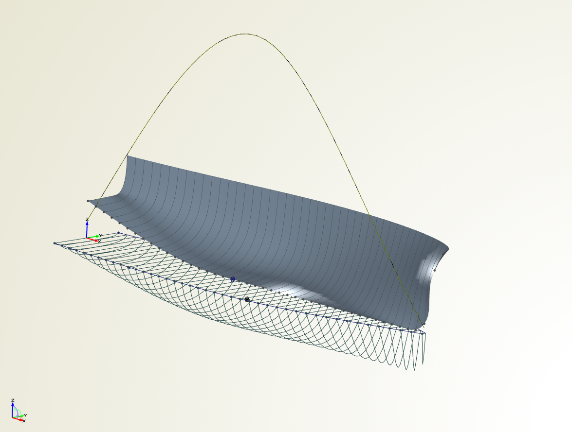
there are different results displayed in the 3D-View and in the table. In the table you can see the scalar results, like displacement and XCB.
In the 3D-View you can see the sectional area curve and the wetted surface area as shown in the screenshot.

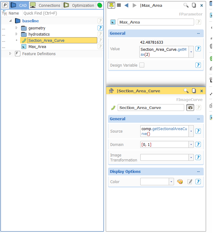
You can utelize the sectional area curve for example, by creating an image curve and based on that you can create a parameter which calculates the maximum sectional area (see screenshot below)
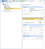
There is no problem doing this with CAESES Free.
Regards,
Simon
-
Hello Christoph,
apparently you forgot to attach the screenshot, which would be very helpfull to understand what the problem is.
Or maybe you can upload your caeses file?
Regards,
Simon
-
Hey Mohamad,
I gave you a more detailed answer here.
Please add any other questions or posts regarding the B-Series in that thread.
Cheers,
Simon
-
Hey Mohamad,
sorry for the delay. We are currently working on a Wageningen B-Series propeller our selfs, so I can only give you a genreal idea how to do it.
First I would highly recommend reading this document, because it explains how the B-Series is build and all the formulas and their values are included:
http://teacher.buet.ac.bd/mmkarim/B_Series_Propeller.pdf
If you want to model it, you have to use a different method than in the generic blade tutorial. I would suggest to follow these steps:
1) create the points for all the profiles (from 0.2 r/R to 1.0 r/R). Out of these points create interpolation curves for all the sections.
2) Use a skinning (lofted surface) to create the main part of the blade
--> These two steps are best done in a feature, for more information have a look at the tutorials regarding features
3) Create the tip of the blade by using a separate feature
4) Create the fillet between the hub and the blade ( Edge Fillet --> See tutorial "Introduction to BReps")

I hope this will give you a general idea how to do it.
Cheers,
Simon
-
Hi Mohamad,
I hope I understood your questions correct. I will try to answer them:
1) The camber/camber line of a B-Series propeller doesn't have a special defintion different from the general defintion. If you want to model the propeller in Caeses it is very easy to create your own camber line. Therfore you could just connect the points with the same X-values of the pressure and suction side. Create a point in the middle of htis line. If you do this for each set of points of a profile and create in interpolation curve in the end, you will get the camber line.
2) The chord line is just a straight line connecting the tip of the trailing edge with the tip of the leading edge, there is no deviation for the B-Series
3) The maximum thickness of each section comes from the tabular data:

To get the thickness just use the formula: Sr = (ar - br * Z) * D
With Z being the number of blades and D the diameter.
I hope this will help you. If you have any further questions just let me know.
Regards,
Simon
-
Hey Ken,
thanks again for reporting this issue. We are now working on a solution.
Cheers,
Simon
-
Hi Johannes,
it is possible to do this kind of operation.
To do so, I would recommend using a Free Form Deformation. I created a small example to show you how it works.
For further information please have a look at the Free Form Deformation tutorials.
Cheers,
Simon
-
 1
1
-
-
Hey,
I have tested your file and it was working for me, when using "export --> STL (colour)".
Which version of Caeses are you using and on what system?
In case you are not using the newest version of Caeses, it might be helpfull to update it.
Best Regards,
Simon
-
Hey,
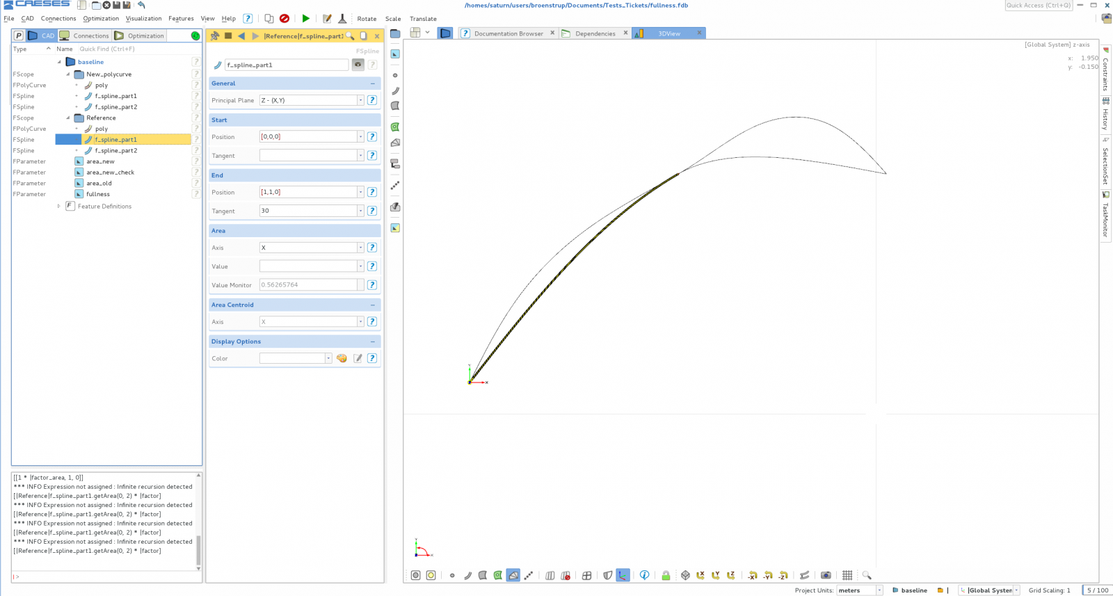
I attached a screenshot on where to find the area of an f-spline.
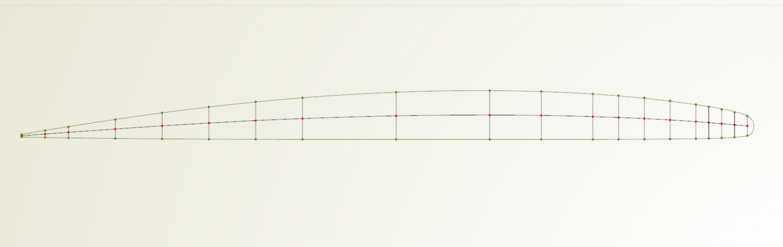
Furthermore I made a little example, of how to change the area of the complete polycurve to a chosen value without changing the positions of the intermediate points:
- There is a polycurve containing tow f-splines in the scope "Reference"
- The parameter "area_old" is the area of the old or "Reference" polycurve
- The parameter "area_new" can be chosen and the paramter "fullness" will be calculated, but it is alos possible to directly choose the value of "fullness"
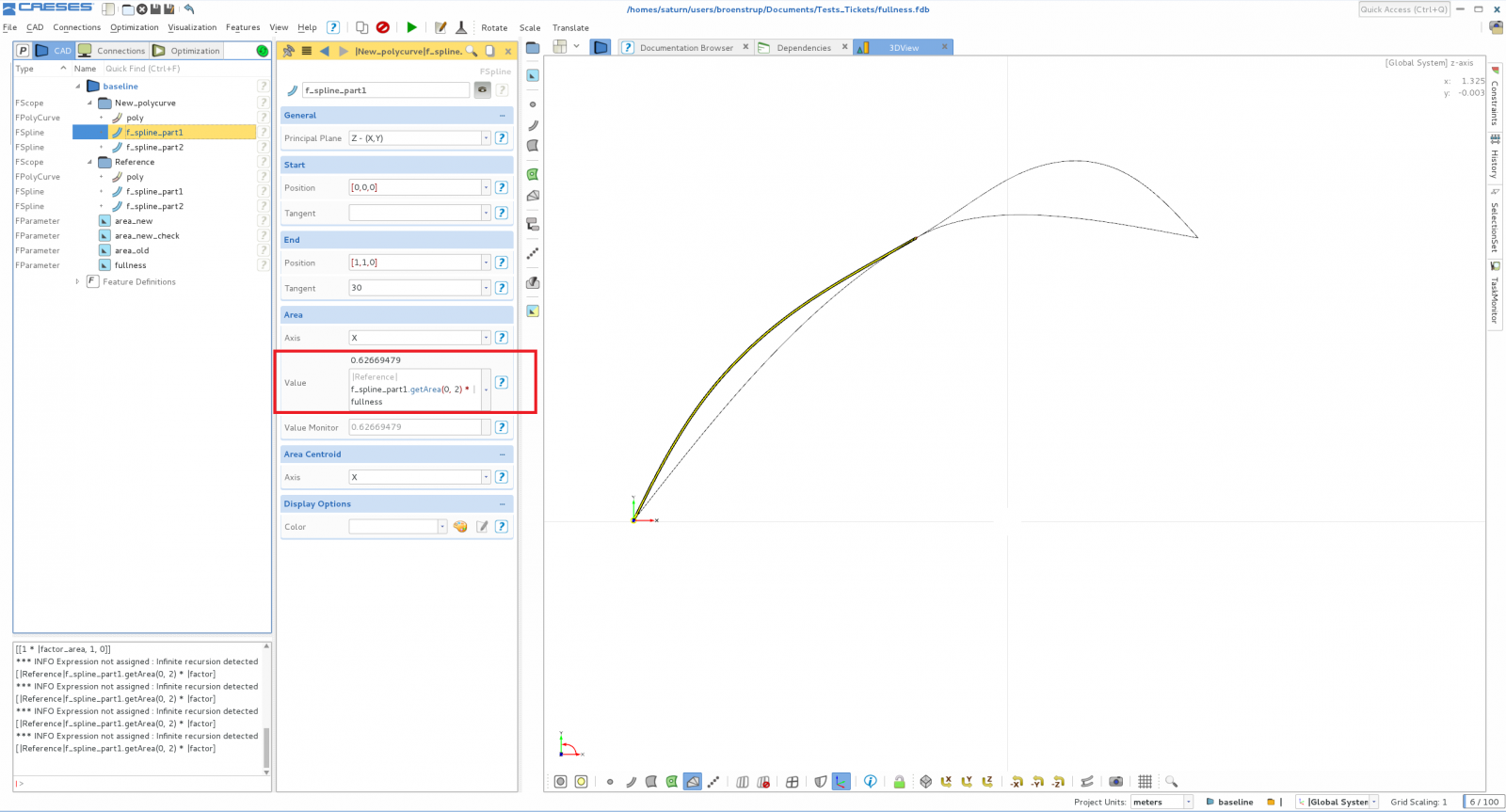
- The new f-splines/polycurves in the scope "New_polycurve" is calculating the new area value (see Screenshot "new_area")
I hope this will help you, otherwise it would be great if you could upload a screenshot of your problem/project.
Regards,
Simon

-
Hey,
you can check the value of each f-spline by clicking on the object in the tree and under "area" you can choose the axis and see the current value behind "value monitor".
If you do not have an f-spline, the only other way to achieve a specific area for the complete curve is to move the intermediate points and check the area under the complete polycurve. This could be achieved using an optimisation.
I hope I understand your problem correctly, if not, it would be best if you could opload the project or a pictue of it.
Regards,
Simon
-
Hey Filipa,
unfortunately there is no way to transform the polycurve into a type of curve where you can change the area.
As you mentioned the F-Spline is the only type of curve where this is possible. So the best way to directly control the area of the polycurve is to use F-Splines as sources of the polycurve.
Depending on how your polycurve is build right now, it would be possible to optimise the position of the intermediate points (start and end points of the objects of the polycurve), so the overall area of the polycurve matches the value you want it to be. But that is more complicated then using f-splines.
I hope this will help you.
Regards,
Simon
-
-
HI Yanxin,
i had a look at your file and your screenshots and fixed the problems. Therefore see the attached file.
The gaps are probably a result of the IGES import and the high number of surfaces, this problem could be solved by remodeling the bulb using a meta surface, similar to what you did at the front of the bulb.
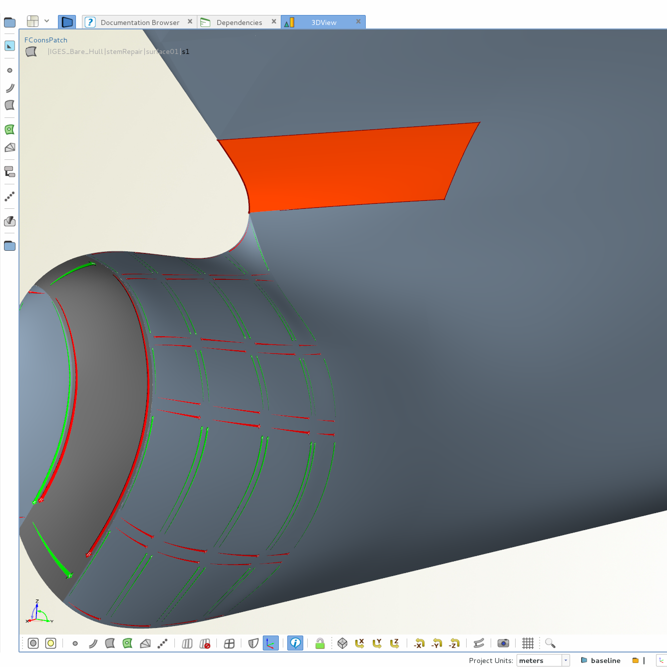
But an easy solution for now, is changing the snapping options of the trimesh (error and tolerance), that is what I have done in the attached file. Furthermore I changed one of your coons patches, so it is not showing you any more errors (see Screen).
The setting for the U- and v-Resolution you mentioned are just a matter of how the surface is displayed. If there is a problem/error with a surface changing these setting cannot fix them.
Best,
Simon


coupling CAESES with seakeeping software
in Software Connections
Posted · Report reply
Hi,
we have done connections between Maxsurf and CAESES before, so it is definitely possible, but thus far we only used the stability application (former Hydromax). It should be possible to also make a connection to control the motions application.
I send you a message with the features we have.
Cheers,
Simon