


Stefan Wunderlich
-
Content Count
85 -
Joined
-
Last visited
-
Days Won
1
Posts posted by Stefan Wunderlich
-
-
Hi Britt,
I would probably do something like this (I did not test it, so I hope it is correct):
// we need to now this from somewhere
unsigned nu(10)
unsigned nv(10)
ffile file("...")
file.openRead()// we need to now this from somewhere, maybe read it from file?
unsigned nu(10)
unsigned nv(10)objectlist points()
objectlist weights()
loop(nu)
// we need to build 2d arrays -> objectlist of objectlists
objectlist rowPoints()
objectlist rowWeights()
points.add(rowPoints)
weights.add(rowWeights)
loop(nv)
string line(file.readLine())
objectList data(line.splitByRegExp("[, ]"))
FVector3 vec()
vec.set([#data.at(0).castTo(double), #data.at(1).castTo(double), #data.at(2).castTo(double)]) // the # detaches the value from the expression
double weight(data.at(3).castTo(double)) // # not needed here since double is always detached
rowPoints.add(vec)
rowWeights.add(weight)
endloop
endloop
nurbssurface surf()
surf.setPointArray(points)
surf.setWeights(weights)
Hope that brings you on the road again. Just ask if you need any further guidance.
Cheers,
Stefan
-
Hi Britt,
I think we really have to clean our command interface at some places, since I had to figure out myself how to do this ;)
This would be a possibility:
// ------------------------------------------------------
string line(file.readLine())
objectList uKnots(line.splitByRegExp("[, ]"))
objectList vKnots(line.splitByRegExp("[, ]"))
// we need a fdoubleseries as type
fdoubleseries uk()
// foreach walks over each entry and performs castto() implicitly
foreach(double k : uKnots)
uk.push_back(k)
endfor
fdoubleseries vk()
foreach(double k : vKnots)
vk.push_back(k)
endfor
nurbssurface FSImport().setName(surfname)
FSImport.setUdegree(uDeg)
FSImport.setVdegree(vDeg)
FSImport.setUknotvector(uk)
FSImport.setVknotvector(vk)
// ------------------------------------------------------
Please be aware that weights are set by objectlist (which is not really consistent).
I hope that helps.
Cheers,
Stefan
-
Hi Britt,
Could you attach a simple sampleproject where the issue is present?
Cheers,
Stefan
-
Hi Britton,
I just dropped in here and I think you are right.
Asurface that has at least an internal nurbs representation (like meta surfaces) should be usable as nurbs.
I will discuss this internally, but I am pretty sure we will come up with a solution for the upcomming 3.1 release (something like implicit usage of the internal nurbs representation if requested).
Cheers,
Stefan
-
For debugging purpose, you could add some "echo" commands, to see which branch it really takes (you will see the output in console):
if (Lratio < 1)
echo("Lratio < 1: " + Lratio)
Lfn.setvalue(Los)
elseif (Lratio >= 1.1)
echo("Lratio >= 1.1: " + Lratio)
Lfn.setvalue(1.0667*L)
else
echo("else branch: " + Lratio)
Lfn.setvalue(L + (2/3)*(Los - L))
endif
Cheers,
Stefan
-
Hi Carlos,
what do you mean by "jumps the else", does it run into the else case if Lratio == 1.05?
The "and" statement works like this:
if (Lratio < 1)
Lfn.setvalue(Los)
elseif (Lratio >= 1.1)
Lfn.setvalue(1.0667*L)
elseif ( and ( Lratio>=1, Lratio<1.1))
Lfn.setvalue(L + (2/3)*(Los - L))
endif
But that does not make any sense since "and ( Lratio>=1,Lratio<1.1)" is implicit for the else case in your example.
Cheers,
Stefan
-
Hi Carlos,
the "and(..., ...)" should be what you are looking for.
Cheers,
Stefan
-
Good that it helped!
Cheers,
Stefan
-
Hi Alex,
from the callstack it looks like there is a custom styleengine (Oxygen) involved.
Could you try starting CAESES with "-style plastique" to override the KDE styleengine? Another option could be to change the style in KDE settings.
If it still crashes, another backtrace would be helpful.
Cheers,
Stefan
-
Hi Carsten,
This is just nice, thank you!
-
Hi Saban,
In general, CAESES-FFW does not provide a COM-interface or anything similar to interact with it from another program at runtime.
Matlab provides methodes to execute system calls (check here) so you might want to run CAESES-FFW with a script file as argument.So you could, have Matlab generate such a script file (*.fsc). Inside the script, you can use the command interface of CAESES-FFW (i.e. openProject("path_to_project"), set values, export geometry or generate custom exports within features).
For a short introduction to the script files, start CAESES-FFW, open the "Global Commands" page in the Documentation Browser and look for the "source(FString)" command (e.g. Ctrl+F, type "source(F").
Cheers,
Stefan
-
Hi Lalym,
you are right, increasing the MarchingAccuracy to i.e. 1.e-8 will lead to sufficient results.
Cheers,
Stefan
-
Hi Matthias,
Currently, only a workaround is possible. We might include a more user friendly version of this in a later release ;-)
I created a simple feature-definition that would insert the image at the beginning of the design-documentation AddImageToDesignDocu.fdf.
You might extend it, it is very simple.
You would then create a feature instance and set the name of the image and the computation.
In the design engine, add a postprocessing command like "[myFeature.run()]" to execute the feature after each finished design (you have to expand "Design Pre/Postprocessing").
You can create more instances if you have more than one image (postprocessing command: [f1.run(), f2.run(), ...]) or extend the feature definition.
I hope that helps.
Cheers,
Stefan
-
 1
1
-
-
Hi Humberto,
I understand, this us not self explaining.
Basically the panelmesh needs a list of points and a series of point indexes that define the panels. Additionally you could have multiple values fur each point (meta data) which I skip for simplicity.
So if you have four points in your pointlist (ordered in rows), you could define a four sided panel in the form of [4, 0, 1, 3, 2] where the first "4" defines a four sided panel.
To define 2 triangles you could have [3, 0, 1, 2, 3, 2, 3, 2].
I think it is easy to understand if you see it, so I attached a sample feature that creates a simple panelmesh (I am open to further questions).
Cheers,
Stefan
-
Hi Daniel,
A short answer to your first question:
You can simply right click on the title bar or the tab in central window of any component and choose top level to detach the window. You can alternatively click the square button in the title bar.
After that, simply drag the window to the second screen.
Your second question will be better answered by someone with more experience in blade modeling ;-)
Cheers,
Stefan
-
1
-
-
Hi Britton,
I just opend the project with the recent 3.0.10 on Win7 64Bit and everything seems fine.
Where does it "hang"? Do you use CAESES 3.0.10 on your PC?
Cheers,
Stefan
-
Hello Matthias,
you might also check the "Mathematical Functions" part in the documentation (Documentation Browser -> Global Commands at the end of the page).
Cheers,
Stefan
-
Hi Jingjing,
Indeed, there is a bug with the connection of the plane cut.
Fortunately, we are just about to finish a maintainance release (3.0.10), so this bug will be fixed then.
The release will be available probably today or tomorrow.
Thanks for your observation!
Best regards,
Stefan
-
Hi,
1. The only way I can think of is what Arne wrote about the camera positions toolbar. Setup your viewport and create a new camera position. Then look into the "toggle on command". The transformation matrix applied there is probably what you are looking for.
2. For the quick filters, there is only an internal command (for which applies what Arne wrote above):
3DScene.setFilterState("offsetFilter true")
where you set true or false to enable/ disable the respective filter.
Following filters are currently used:
pointFilter
curveFilter
surfaceFilter
meshFilter
offsetFilter
You can also set multiple filter states by using expressions like this:
3DScene.setFilterState("surfaceFilter true\noffsetFilter true")
3. There is no command to turn isometric view on or off. You can change the view by using
3DView.rotateToIsometric...()
(same like you did with rotateToXAxis()).
I hope that helps.
Cheers,
Stefan
-
Cool, did not know that these things are really huge - wow.
Cheers,
Stefan
-
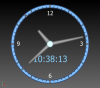
Hi,
this morning, I had some fun with the "timer" example and extended it to a full working "analog" clock, so I thought I just share the result with you.
Even if it is not really useful, it makes use of some interesting technics like features, timers, boolean operations with solids and labels.
Last but no least it eats up about 30% of the CPU resources of my 8-core machine (mostly needed for calculating the boolean operations) ;)
Have fun,
Stefan
-
1
-
-
Hi Bodo,
just for your information: 3.0.2 is available, including the mentioned implicit cast.
Cheers,
Stefan
-
Hi Bodo,
I think it is not "wrong" but it breaks usability ;-)
So we included an implicit cast from FPolyLine to FOffset to get rid of ".castTo(FOffset)" (next maintainance release 3.0.2).
Thanks for finding it!
Cheers,
Stefan
-
Nice trick :)

Chines in BSpline Surfaces/Images
in General Modeling
Posted · Report reply
Hi Britt,
good to hear that it works now.
Cheers,
Stefan