


Mr. Daehwan Park
-
Content Count
67 -
Joined
-
Last visited
Posts posted by Mr. Daehwan Park
-
-
Hi,
CAESES users who work for ship's hullform design might have met at least once a very embarrassed moment that some offsets are disconnected and very hard to achieve safe offset groups.
I attached a cookbook and a CAESES file OffsetExt.fdb for safe offset group creation.
The Cookbook is very short but in the project file there are several feature definitions which are valuable to look inside and understand how to control offset data.
I wish it helps.
Daehwan
-
Hi
I attach here a cookbook for partially parametric hullform variation and its project file.
I hope you enjoy it and imagine something good!
Daehwan.
-
NAPA exports its wire frame model as DXF file.
CAESES imports it and applies form-variation functions.
The final variant is exported as IGES curves and NAPA import it again.
Something beautiful would be happned with NAPA + CAESES.
( The animation : http://daehwan2034.wordpress.com/2014/09/18/caeses-varies-napa-wireframe/ )
-
 1
1
-
-
Hi Carlos
I have 3 whys.
Q1. Why do you making another surface even though you have already IGES patches.
Q2. Why do you make OffsetGroups ?
Q3. Why do you extract OffsetGroupBaseCurve ?
Your answers will help to understand the problem and find the proper support.
Regards
Daehwan
-
Good to hear that.
Actually all what I did with CFAST was to read the page 23 and select out the input and output files of CFAST the BLACK BOX for me.
In other words, I have no idea what CFAST does and I just acknowleged it is related with Fire and Smoke.
When you have an optimization model please don't forget telling us.
Tschao -
Daehwan
P.S. Im welchen Studiengang bist du ?
-
Hi Tobias,
Please see the attached file.
The project file is saved in fCloud ( https://www.friendship-systems.de/fcloud5/public.php?service=files&t=218cc3a341fe4f91733fa6da96b52135 )
Question :

I need some materials introducing CFAST cases for optimization.
Do you have ?
Cheers
Daehwan.
-
Hi Tobias
I made a case.
I'll be back soon. B)
Daehwan
-
Hi Prabu
How much do you know about transformation in CAESES?
Just for bulb tip variation, deltaShift and deltaProduct skills were used.
When you are not familiar with deltaShift, please get helped by CAESES documents first (samples >> transformations).
Regards
Daehwan.
-
Hi Prabu,
Yes, deltashift function should be used.
Technically in CAESES bulb tip variation without affecting forebody is possible but it seems not so effective for the better retrofit in the view point of hydrodynamic performance since the variation will happen within too narrow range.
When the hullform could be exported as IGES or STL file from NAPA, they could be imported again in CAESES and be formally varied with the combination of deltashift functions.
Regards
Daehwan
-
The procedure seems understood like this.
Step 1. FFW exports hull form variants.
Step 2. A code calculates wave resistance.
Step 3. A code evalutates the minimum resistance.
Step 4. If this procedure did not stop at step 3, step 1 starts again.
The software connection chain for the two external programs are possible when they run under batch mode.
The actual matter is that CAESES
demoversion does not provide more than 3 or 4 variants.If you are a student, you could have chance to experience full optimization with the combination of FFW and your in-house code.
Please read the "Free Academic Pro Edition for Students" in the linked page below :
http://www.friendship-systems.com/products/friendship-framework/licenses
If you are not a student, please make a contact with support@friendship-systems.com to be guided.
Best regards
Daehwan
-
Hi Shahriar
First of all, we need to clarify the input and output features. Please give us some more detailed information about them.
[input files] - [executables] - [output files]
--
Daehwan.
-
DeltaShift is one of the key functionality in FRIENDSHIP-Framework for hull form variation.
DeltaShift can be uses as a position-shifting function and also as, so to say, influence function.
DeltaProduct is another functionality which multiplies all DeltaShifts selected.
In the attached file, there is a way to arise the tip of bulbous bow not effecting stem surface.
From now on, Goose-neck and Rem type bulbous bow could be made by this partially parametric variation method.
// Daehwan
P.S. Some gif animaton could be found at the blog :
http://daehwan2034.wordpress.com/2014/05/15/bulbous-bow-tip-variation/
-
Ladies and Gentlemen !
I uploaded another post about the combination of CAESES and STARCCM+.
This time the subject is CAR.
Before going into 3D field, we tried 2D profile analysis.
This is not completed project but I want to introduce you the stroy.
-
Ladies and Gentlemen
I have a short introduction about the evaluation project of propeller open water test using CAESES + STARCCM+.
You can find the whole contents at the link below.
:D
-
Dimension, position and pitch angle of PBCF are variable.
This provides Watertight colored STL.
Propeller and Fin are given with thickness at their trailing edges and tips.
Since all of these models are defined parameters, propeller can be varied, too.
This is the basic concept of the form variation and positioning of PBCF.
The geometry of PBCF can be exchanged with the other properly shaped fin model.
Cheers!
Daehwan
-
Hi Amitava
Before coupling CAESES-FFW and STARCCM+ you have to set up the working environment.
When you install CAESES-FFW in the same computer with STARCCM+ then we can start talking about the connection job.
In the case that each of the software is installed in the different computer like your situation now, we have to use sshResourceManager to make the two software communicate. The install files and guidebook are in the folder : .../tools/sshResourceManager.
If this working circumstance is not prepared the connection is unavailable.
And CAESES does not support full iteration for optimization. As far as I know just 4 variants could be generated by the optimization engines.
The pro version of CAESES, i.e. FRIENDSHIP-Framework is needed to get to the end of your research with regard to optimization.
Best regards
Daehwan.
-
Dear Lazauskas
How happy it is to see you here!
As explained by Ben, all can be possible.
Two things must be considered.
1. If the external program like Mitchlet has no command file to make it run without manual mouse clicking or key putting, the automatic process could not be performed. Fortunately, however, I have heard that there exists an extra simple code which provides a batchmode run for Mitchlet. Then we can use that batchfile to trigger the program. Of coirse the output must be produced by the program in a file. I believe you know this already.
2. As far as I know, CAESES has the limitation of iteration number for the full optimization. So before getting into final case CAESES should be upgraded to Friendship-Framework.
Other geometric issues will be surely and properly controlled in CAESES or FFW.
Let's be in contact.
Best regards
Daehwan.
-
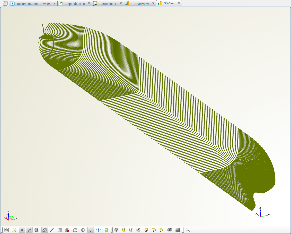
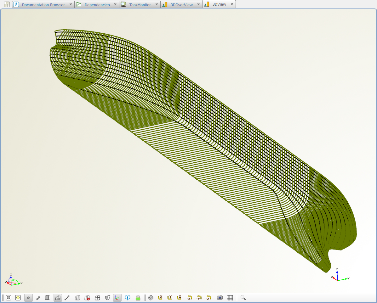
Suppose an optimization was done with SHIPFLOW and the offset data was also changed.
Usually fairing and lines drawing follow in the next step.
In these phase, several names of software break up in my head like Rhino3D, NAPA, AutoCAD, POLYCAD, ezHull and e.t.c.
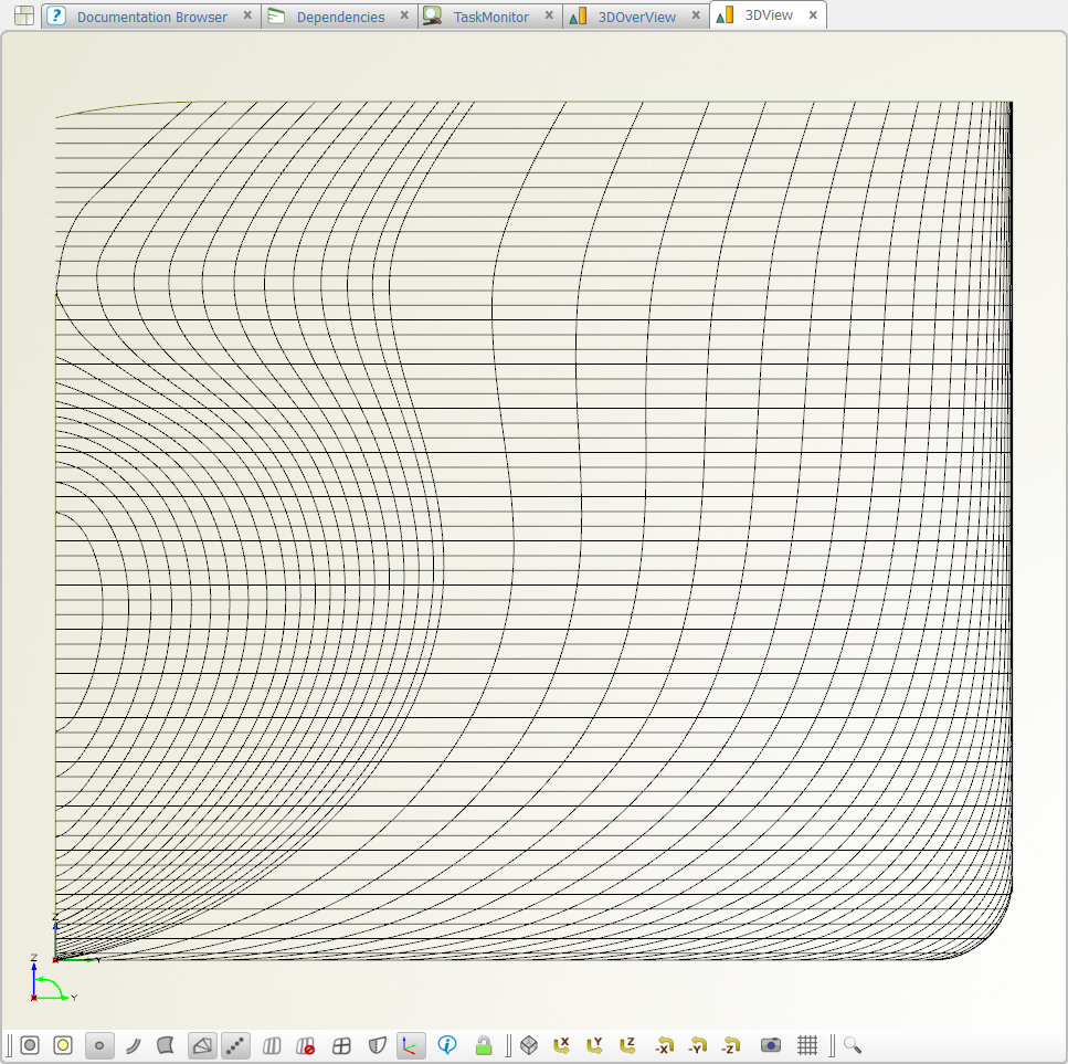
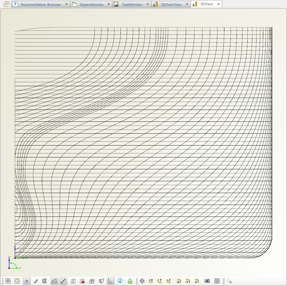
The wireframe created form offset data is converted to iges.
All the second software could import reuse it, i.e. the designer does not need draw lines from the beginning but just manipulate. I hope this would be helpful enough to reduce the M/H practically among the office tasks.
I am gonna close the first feasibility study.
The insights of this task could be arranged like below :
- Stem part was not handled since my offset file does not have it.
- Offset data must be SHIPFLOW type.
- Wireframe is exported as IGES format.
- The quality of wireframe comes from that of offset data.
- The number of control points and wireframes must be able to manipulated in the next software.
This product of this study is not so completed that I would not distribute the project file right now.
When the positive signals are delivered and accumulated, I will reopen this issue and develop it for the better usage.
// Daehwan.

- Stem part was not handled since my offset file does not have it.
-
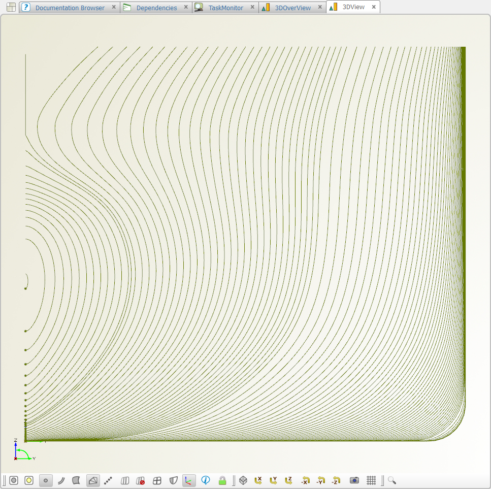
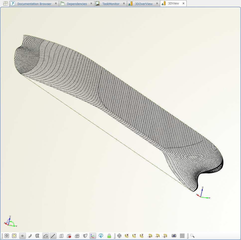
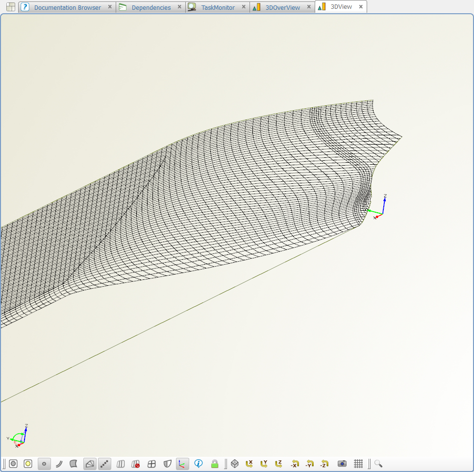
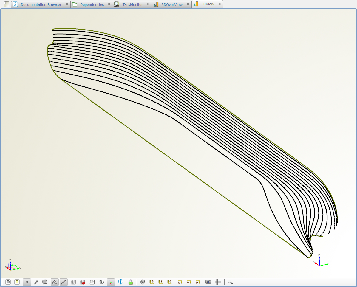
We meet frequently the need to obtain wire frame model from offset data or even from a surface model.
I am not quite sure how this trial will be applied to the practical work, I planted a seed to create waterlines from the KVLCC offset model at the arbitrary z position.
All curves are InterpolationCurve with degree of 3.
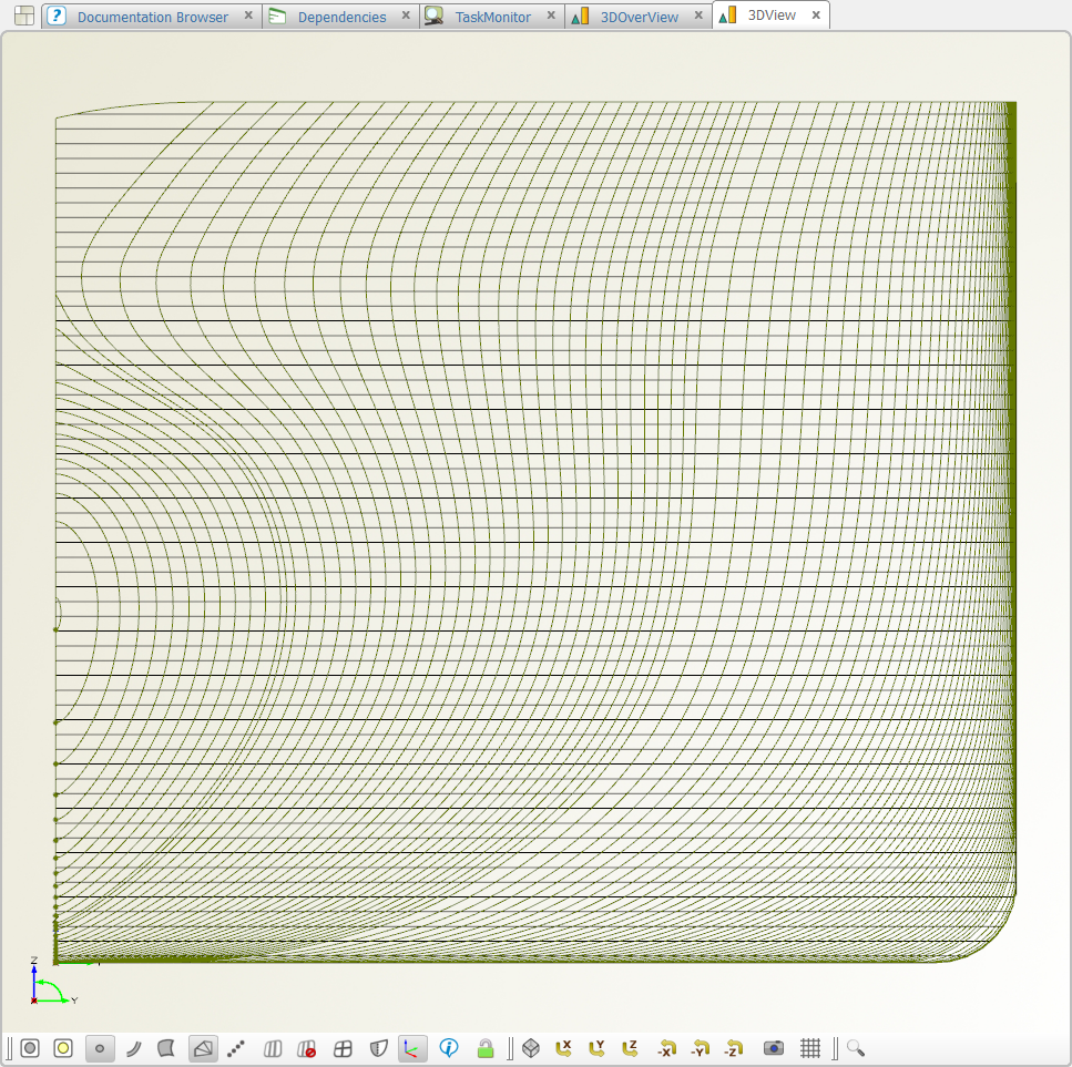
The next step will be the section extraction from the waterline at the arbitrary x positions.
The current study performs in the geometrical scope of single-skeg and normal bulbous bow.
When the original model has a goose neck bulb or twin-skeg, then the order to create the wires should be started from buttock lines.
Am I right?
// Daehwan.


-
The key of integration with STARCCM+ is JAVA-Macro.
Once we have a successful java-macro CAESES reproduces it every time when the new variant is created.
Actually CAESES does not need to know how JAVA-Macro works in STARCCM+.
CAESES just gives the data STARCCM+ requires and takes the results STARCCM+ provides.
The java-macro in this case was written by CD-Adapco Nurnberg Germany.
This material was presented in the KWEA conference 2012. (Korean Wind Energy Association)
// Daehwan -
FRIENDSHIP-Framework changes the geometry data to STARCCM+ friendly format.
See how FFW makes the rough IGES file clean enough for STARCCM+ to adapt the geometry without any manipulation before meshing process.
As a bonus, you could find a innovative elbow pipe case after FFW's optimization using STARCCM+.
This material was introduced in the users' meeting of CD-Adapco Korea 2012.
// Daehwan
-
Hi Chris
Flotilla 5.0 in a few weeks could be the alternative, right?
Let's see what we can do in cooperation.
What is your goal with the softwares?
// Daehwan.
-
Hi Chris
Have you tried Volodim's program, i.e. automitchlet.exe ?
If it was successful then let me/us know it.
Daehwan.
-
Hi Chris,
I am Daehwan.
I know the problem you have.
Pressing the buttons (R and T) means issuing a kind of "KEY_PRESS_EVENT" or "MOUSE_CLICK_EVENT".
In this way the generic integration could not be constructed.
The external program must be executed just with the command files or batch files.
If the developer provides command files to run Mitchlet then the integration will be done easily.
This information could be helpful for you to understand the coupling better.
Daehwan.
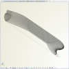
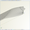
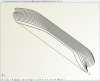
Twisted rudder with Costa bulb
in General Modeling
Posted · Report reply
Thanks for this!
The trimesh of rudder_blade is combined with both parts.
Is it reasonable for any purpose?
Daehwan.