


sisi
-
Content Count
16 -
Joined
-
Last visited
-
Days Won
1
Posts posted by sisi
-
-
Just now, Ceyhan Erdem said:Hi Sisi,
There must be an error in your setup.
Can you please provide me your Caeses project file, fsc file together with your Ansys project file.
You can send them to erdem@friendship-systems.com.
Cheers
Ceyhan
Hi Ceyhan,
I will send an email to your email as soon as possible. Thanks for your answer.
Cheerssisi
-
19 hours ago, Ceyhan Erdem said:Hi Sisi,
Glad that it worked. Please remember that due to changes in design, your BRep Edge numbers may change as well. Creating an inconsistency and hence failure to assign a color.
You can use the attached simple Feature Definition where the user is expected to add the edges that will create the 2D geometry as input. Please assign the colors to the edges before adding to the list.
The fature then will create a BRep using the provided edges and then assign those colors to the corresponding BRep edges.
Cheers
Ceyhan
Hi Ceyhan,
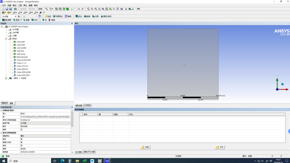
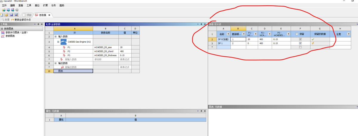
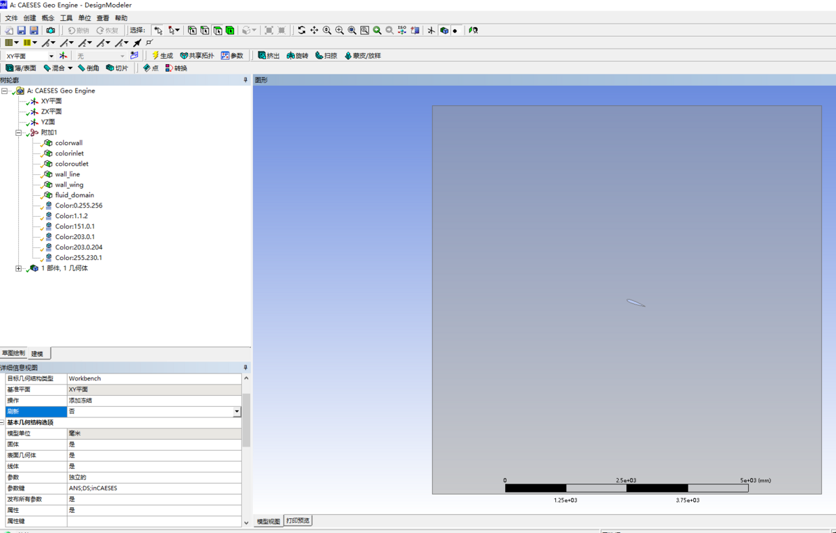
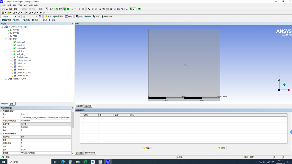
I'm sorry to bother you again. I still have problems with parameter updates.
At the moment, I can change the parameters from DP0 in the workbench parameter set, and the model changes in the DM as well. But when I update the design points DP1, DP2, DP3...... , there will be no changes to the model in the DM (picture1). I've changed some settings about DM, but it's still not going well. Also, for some reason, in DM, the parameter bar is blank(picture3). Earlier when I used solidworks to import a parametric model, I needed to tick the parameters in the DM.
I hope you will be able to help me with this. The following images may help.

-
Hi Ceyhan,
Thank you very much for your answer, my switch to DM did work and now I can do 2D automated solving.
Cheerssisi
-
On 4/24/2018 at 12:05 AM, Mr. Matthew Wegener said:Hi Ceyhan,
I can confirm that I did this.
Hello, I would like to know how you solve this problem. My 2D model import to workbench does not include the named selection.
-
Hi everybody,
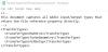
I can't pass the boundary conditions of a 2D model to Ansys Workbench SCDM, even though I've defined inlets, walls, outlets with colors and imported Workbench by ACT APP. -
2 hours ago, Ceyhan Erdem said:Hi Sisi,
I cannot recreate the problem. I will suggest we have a web-meeting to speed up the process.
Please let me know when you may be available on the next days. Please keep in mind that we are using CET time zone.
You can send your availability information to erdem@friendship-systems.com.
Cheers
Ceyhan
Hi Ceyhan,
Thank you for your responsible answer. Since my native language is not English or German, I am not proficient in listening and speaking English or German, and I can only read English words. Unfortunately and sorry, I was unable to communicate through the meeting.
To solve the problem, I will spend some time reproducing my simulation and recording a video, uploading my source file to illustrate my situation.This upload will be a day lateBest wishes.
sisi -
21 hours ago, Ceyhan Erdem said:Hi Sisi,
Can you please let me know your Ansys version?
Did you get the ACT App from the Caeses installation folder?
Cheers
Ceyhan
Hi Ceyhan,
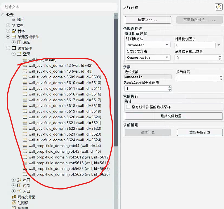
Yes, I used the correct act app. My version is Ansys 2021R1..The image below shows workbench and the changed wall names in fluent. I wonder if it's a problem with fluent meshing?Best wishes.
sisi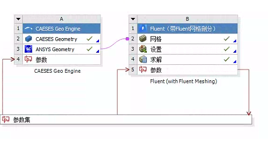
-
On 4/2/2024 at 5:33 PM, Ceyhan Erdem said:Hi Sisi,
Can you let me know how you imported the parametric geometry into Ansys Workbench?
You can name surfaces in Caeses by providing colors to the surfaces of interest which then will be transferred downstream.
Cheers
Ceyhan
Hi Ceyhan Erdem,
I connected the parameterized Caeses propeller model with Workbench via Workbench's ACT plugin. Prior to this, I had already used different colors to identify the boundary conditions in Caeses, including inlet, outlet, wall, wall_prop, etc. Fluent meshing and fluent have no problem with the recognition of boundary conditions. In fluent, wall_prop becomes a name prefixed with "wall_prop" and a number as a suffix, for example: wall_prop20, wall_prop4003, and so on.
The problem is that every time I update a new design point and update the grid, the suffix numbers of these names change, and this change seems to be irregular. Since I set the force and moment of the propeller surface as output parameters in fluent, the original wall_prop name I selected disappeared and the new name was not automatically selected wall_prop.
The above is the problem I encountered with workbench automatic simulation, I don't know if you can solve it.
Best wishes. -
Hello everyone
I built a parametric propeller model using Caeses and imported it into the Workbench platform, meshed it with Fluent Meshing, solved it with Fluent, and I had a problem with solving failures.
I named the propeller surface "wall_prop" and selected all the wall_prop named faces in fluent to establish the output as thrust and moment. However, whenever the parameter points are changed and the mesh is updated, the original name will become wall_prop_1, wall_prop_2...... the original name will disappear, and the output torque and force will not automatically select the new name, resulting in the calculated thrust and torque being wrong or the software directly reporting an error.
I don't know how to solve this problem so that the automated simulation can continue. -
Dear Andreas,
Thank you for your answer. I've noticed you mentioned this, but this doesn't solve the problem. In CAESES, my fluid domain length is 4.2m. When I set it to meter on the above page, it's 4200m in ANSYS Workbench. When I set it to milimeter on the above page, it was 4.2mm in ANSYS Workbench. So neither of these units can get the right value, and that's what confuses me for a few days.
Sincerely, respects.
Si Si -
On 1/18/2024 at 6:52 PM, Andreas Arapakopoulos said:Hi again,
I recommend starting by examining the sample propeller provided in CAESES, as it offers a comprehensive representation of geometric modeling for a propeller, encompassing both the hub and tip.
Best Regards,
Andreas
Dear Andreas,
Thank you. I solved the problem of propeller modeling from the example you mentioned above. After that, I started the simulation. I looked at the tutorials and cases of the workbench interface.
However, when I finished building the model and importing it into ANSYS Workbench, I looked at it in SCDM and the model was always magnified 1,000 times. This makes automated simulation and optimization impossible.
I'm guessing there might be something wrong with workbench's unit system, and my setting of SI units to default is invalid. I wonder if you can solve this tricky problem?
Sincerely, respects.
司思Si Si -
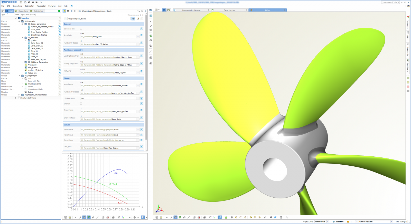
On 1/16/2024 at 3:19 PM, Andreas Arapakopoulos said:Hi Sisi,
The B-series propeller is currently not available as a sample in CAESES.For a design of such a propeller, you can visit our web application at: https://www.wageningen-b-series-propeller.com/
Additional information about these tools can be found in this post: https://www.caeses.com/news/2018/wageningen-b-series-online-propeller-tool-released/Given that the B-series is widely recognized as one of the most comprehensive and commonly used propeller series in marine propulsion, you can also access extensive information in various academic papers.
Alternatively, you can explore a conventional propeller sample that is not based on the B-series. This allows you to independently examine a typical propeller workflow within CAESES.
Best Regards,
AndreasDear Andreas,
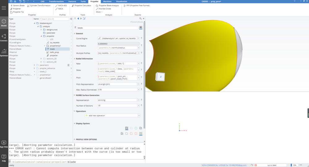
Thank you for your help. What you share is useful, I'm currently making some progress with Propeller Blade Analysis. At the moment I have a new problem, tips can't be created on the propeller.
Thank you again for your help.
Best regards
司思Si si -
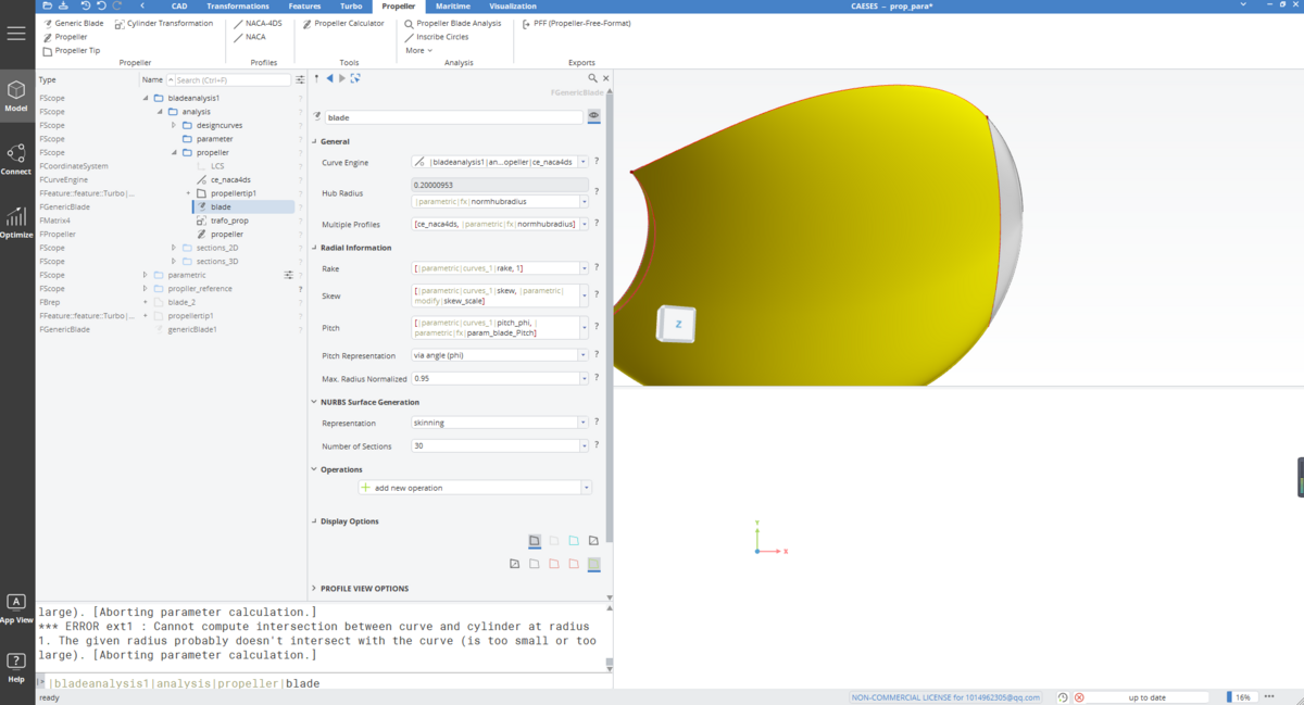
HI everyone,
I'm having a hard time. I created the blades and tips. As shown in Fig. However, when I create the propeller with Model-propeller-propller, I only get incomplete blades. The tips were not created together. This is shown in the image below.
Also, due to the language, I may have a problem with the description not being clear, so please forgive me.
Looking forward to your answer.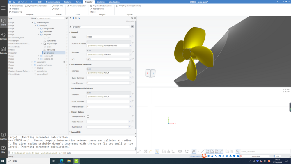
-
 1
1
-
-
Hi,guys,
excuse me .I can't find the B-series propller in CAESES sample. How could get or design it ? I have to implement it in my project.Can you give me some advice or help with the B series?
Looking forward to your reply.
Thanks. -

CAESES & Workbench SCDM
in Software Connections
Posted · Report reply
Hi Ceyhan,
Sincerely thank you for your reply, I carefully looked at the model you sent me and re-set it as you suggested, it was of great help.
Cheers
sisi