


Mr. Bastian Ahlf
-
Content Count
21 -
Joined
-
Last visited
-
Days Won
2
Posts posted by Mr. Bastian Ahlf
-
-
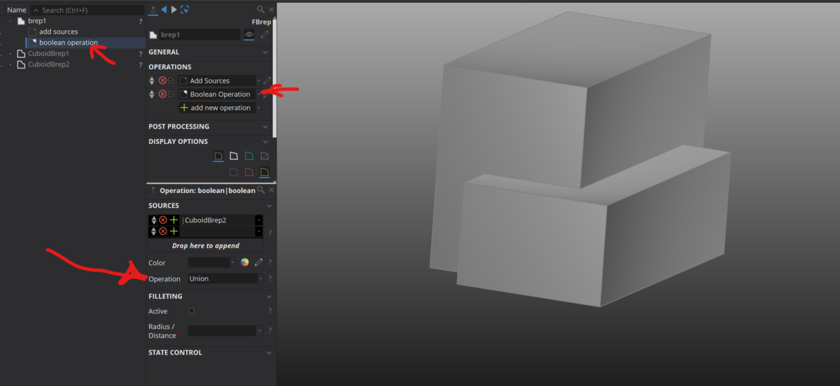
Without being aware of your exact plan, would it be a sufficient workaround to substract a cylinder by means of a boolean operation?
-
Hi,
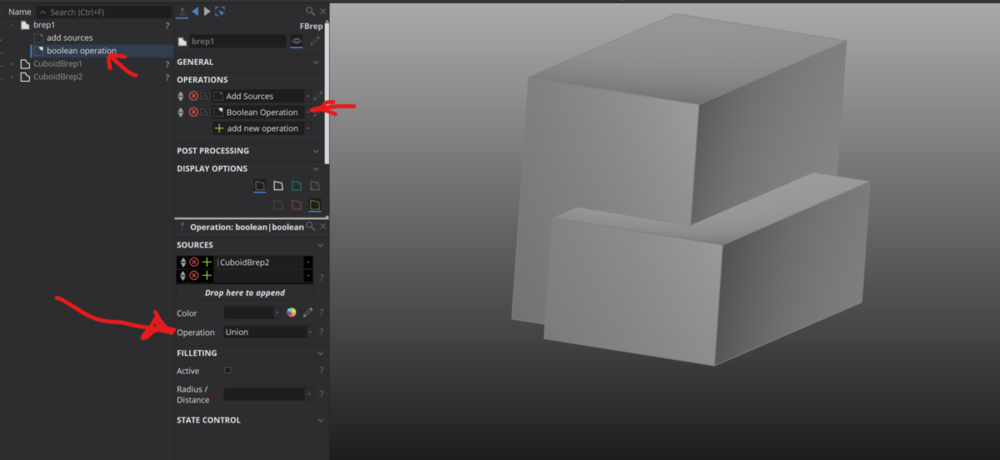
please try "boolean operations" within the brep creation after you added a source once.
-
Hi, could you please provide more information how you created the Brep you want to export comprising the four single parts?
-
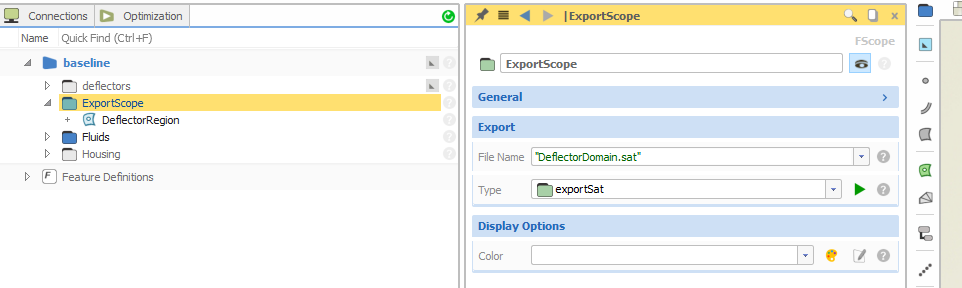
Please ensure your export folder has the correct setting as shown in my first screenshot from monday.
Furthermore, you could have a closer look what is exported by Caeses when updating a parameter in this file path:
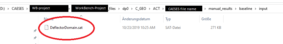
-
 1
1
-
-
I assume the first part of the error message "Error: No compatible interface found for this file type" refers to the exported file type.
Please try different file types like .stl, .step, .sat and so on
-
Hi,
the CAESES-file and the workbench do not have to be in the same directory. To check if the DesignModeler receives a geometry, just open it. By updating the CAESES module in the workbench, the FSC-File opens CAESES, exports the geometry and so on. You do not have to deal with other exports than your FSC-file.
My screenshot above originates from CAESES. Please check the folder you want to export, its content and the names as shown in the screenshot.
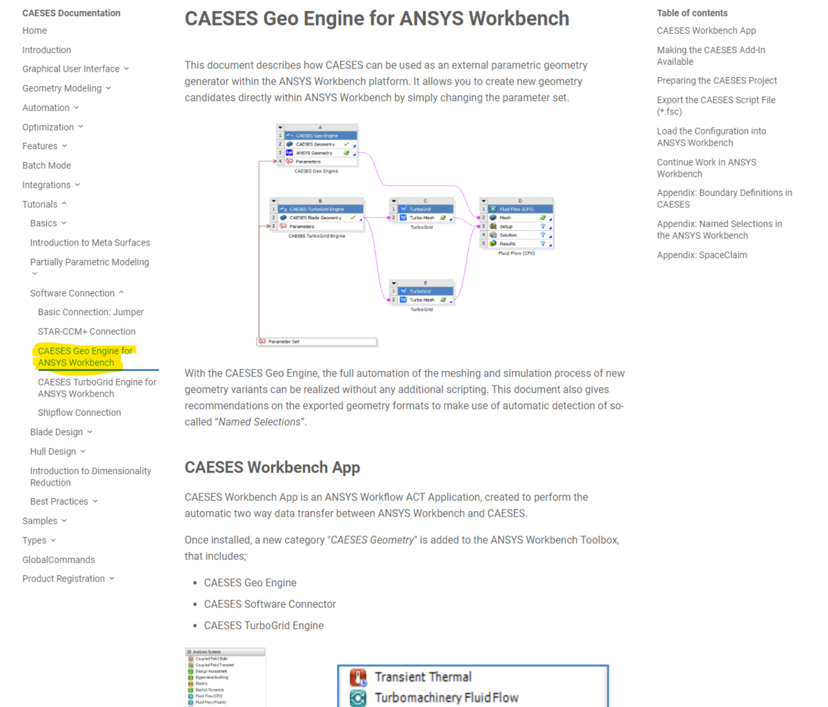
In case you did not read it so far, CAESES provides a perfect and detailed manual how to achieve your objective:

Best wishes
Bastian
-
Hey,
have you checked if your desired geometry is imported correctly in DesignModeler? It is important that your part name has the correct ending. For example if you export a sat-file, name it "whole_part.sat" as shown in the screenshot below. Furthermore, give it a try without an underscore in the name.
Best wishes
Bastian
-
If you created the other surfaces with "Coons Patch" by use of 4 boundaries, you could divide the current 2 lines into 4 lines with "image curves" and use them as boundaries for a "Coons Patch"
-
1
-
-
Hi Ceyhan,
many thanks for your advice.
In case the names remain constant for surfaces, I am going to use their edges for measuring.
Best wishes
Bastian
-
Hi,
in my script i need to measure a length. The length that has to be measured (and adjusted afterwards) ends with the trailing edge of the following blade. The adjustment works well, but before running a huge DOE, i would like to know if the internal names remain unchanged after parameter update.
In the attached picture i tried to visualize my question. The certain edge is named with "2" and can be found with BrepName.getEdge(2).... After some geomtry updates the name did not change and the correct edge was chosen - but is this ensured in any case?
Many thanks
Bastian
-
Hi Bastian,
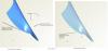
Can you try to extend the hub curve a bit, so that the stacking line does not start at the begin of the hub section?
best regards
Carsten
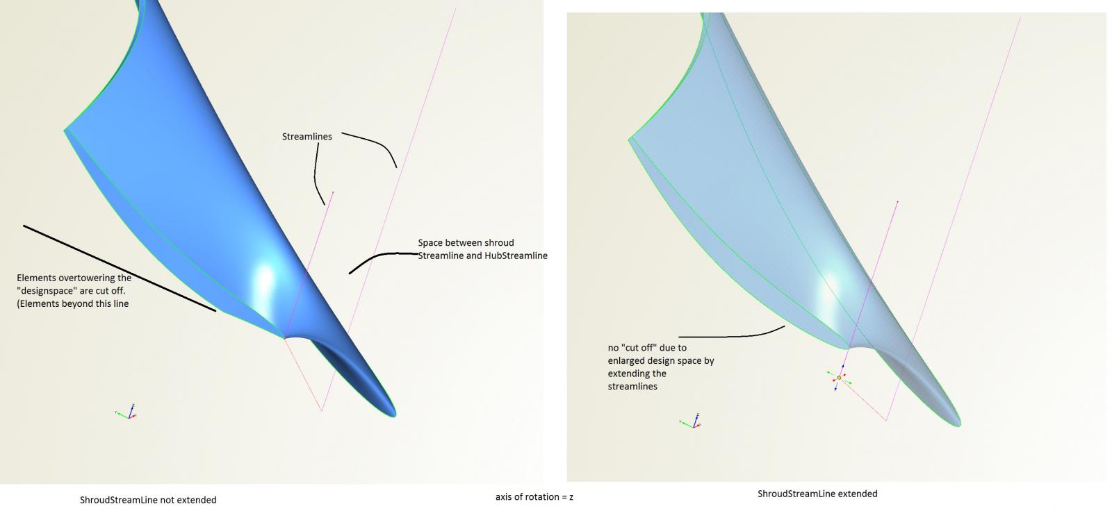
Hi Carsten,
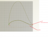
i also found this solution to achieve a round leading edge. Obviously it is not allowed for elements to overtower the "design space" limited by a linear connection between the stream lines. I have tried to visualize in the picture attached if anyone else encounters this issue.
kind regards
Bastian
-
Hi Carsten,
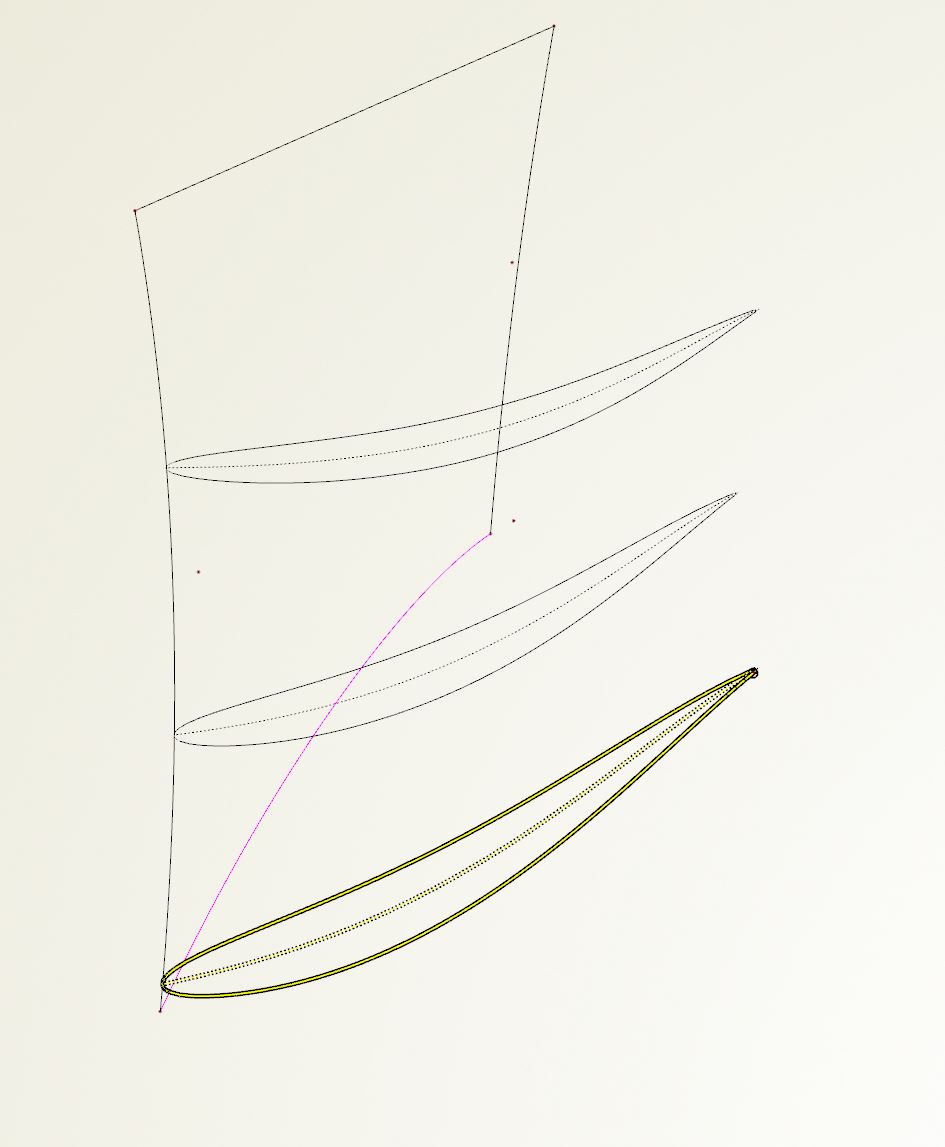
i hope the following informations are helpful. Furthermore i found a way to circumvent the angular leading edge.
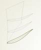
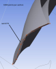
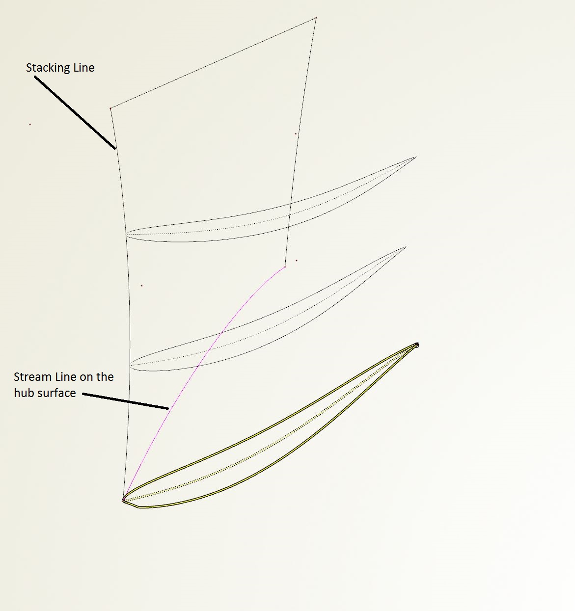
In picture "1" you can see three spans. Each span is created with the stream section feature and is related to the same thickness distribution, beta distribution and stream lines. As shown the first profile has an angular leading edge while the others are fine.
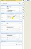
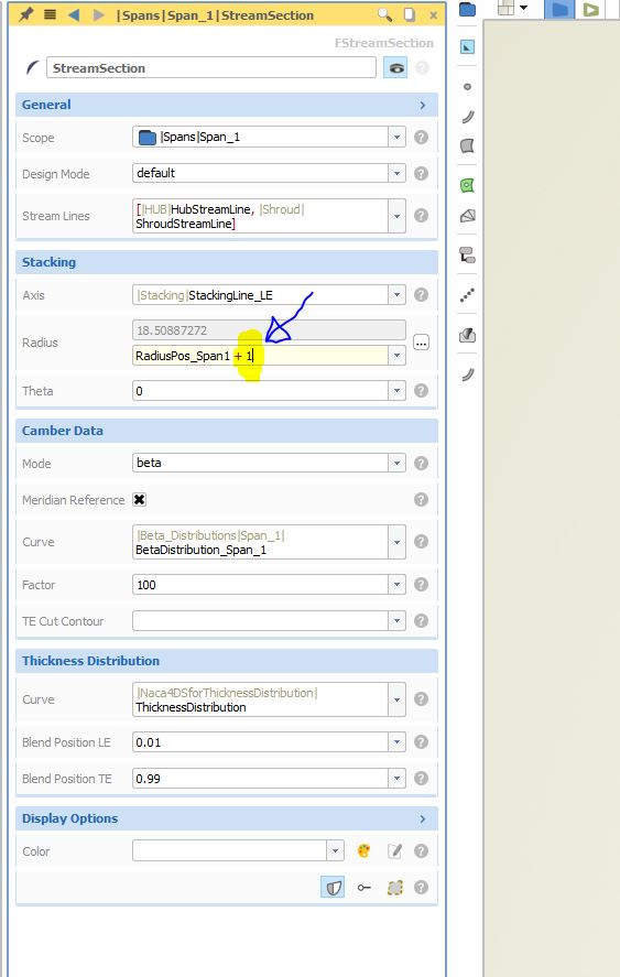
As soon as the first profile is moved away from the hub surface, the angular leading edge disappears as you can see in picture "2". This is done by adding in an offset for the radius on the stacking shown in picture "3".
To achieve a suitable blade, i relocated the stream line on the hub by the mentioned offset. I assume this is not the most elegant solution but it works transitionally.
Kind regards
Bastian
-
Dear Ceyhan,
as it seems the error message was a single phenomenon.
Initially i was not aware CAESES creates Turbogridsessions for each export-feature.
For me the issue is completely resolved.
Kind regards
Bastian
-
Hi Ceyhan,
two Turbogrid sessions are created for two export features - up to here it is fine. But is the script trying to update those two Turbogrid sessions simultaneously? Because i am receiving error messages. Unfortunately i have got only one Pre-license available...
Kind regards
Bastian
-
Hi Bastian,
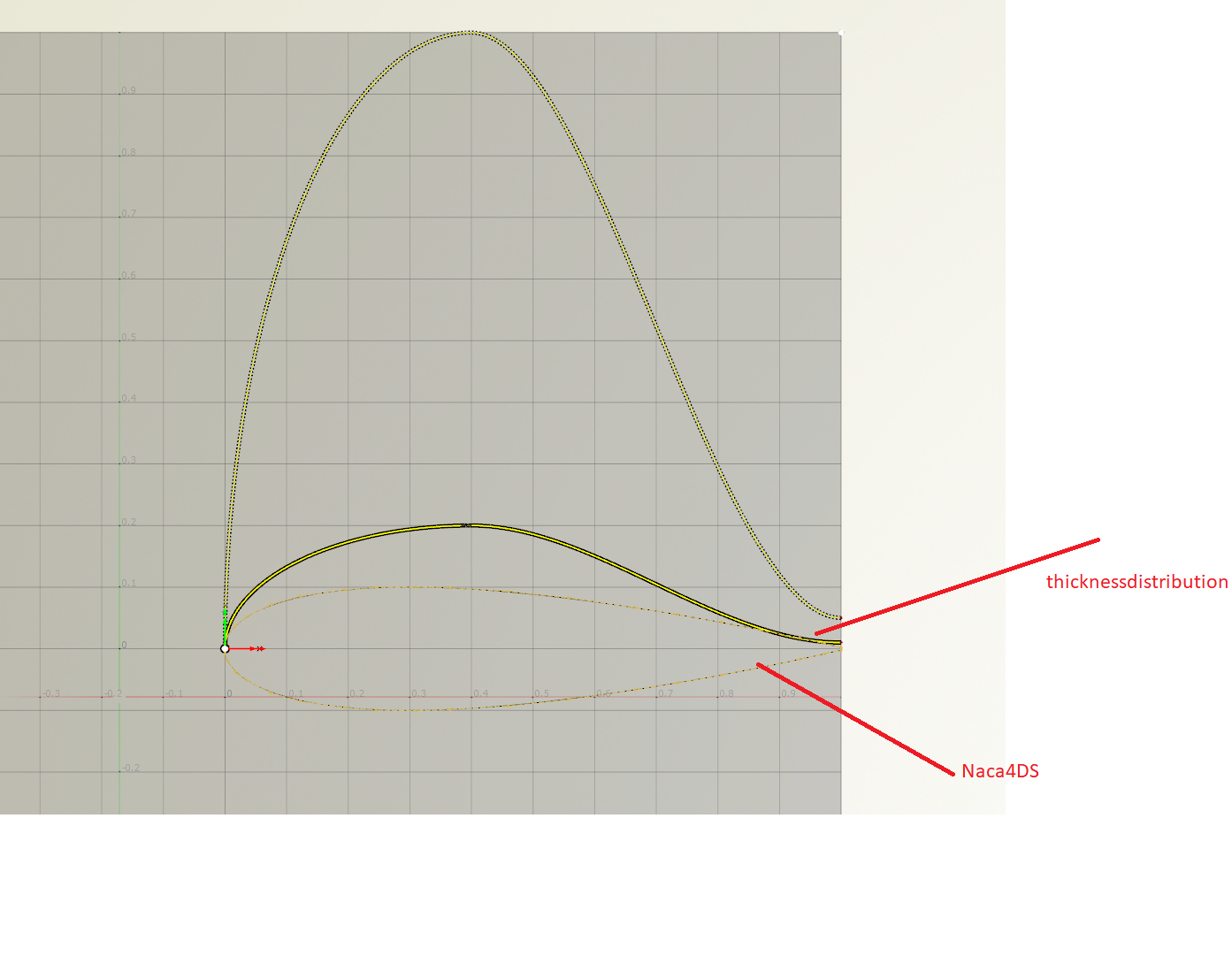
can you show the thickness distribution?
best regards
Carsten
Hi Carsten,
in the attached picture you can find two curves i have applied for the thickness distribution within the StreamSection.
It is a Naca4DS curve and thicknessdistribution is you proposed.
Kind regards
Bastian
-
Hi,
i have tried the suggested workflow to optimize a rotor of a fan with the use of CAESES in combination with Turbogrid and CFX and it works really well.
For machines comprising several blades rows e.g. rotor and stator, is there a way to use the CAESES Turbogrid-Export feature? Because i have not found the option to export a second blade row.
Cheers
Bastian
-
Hi,
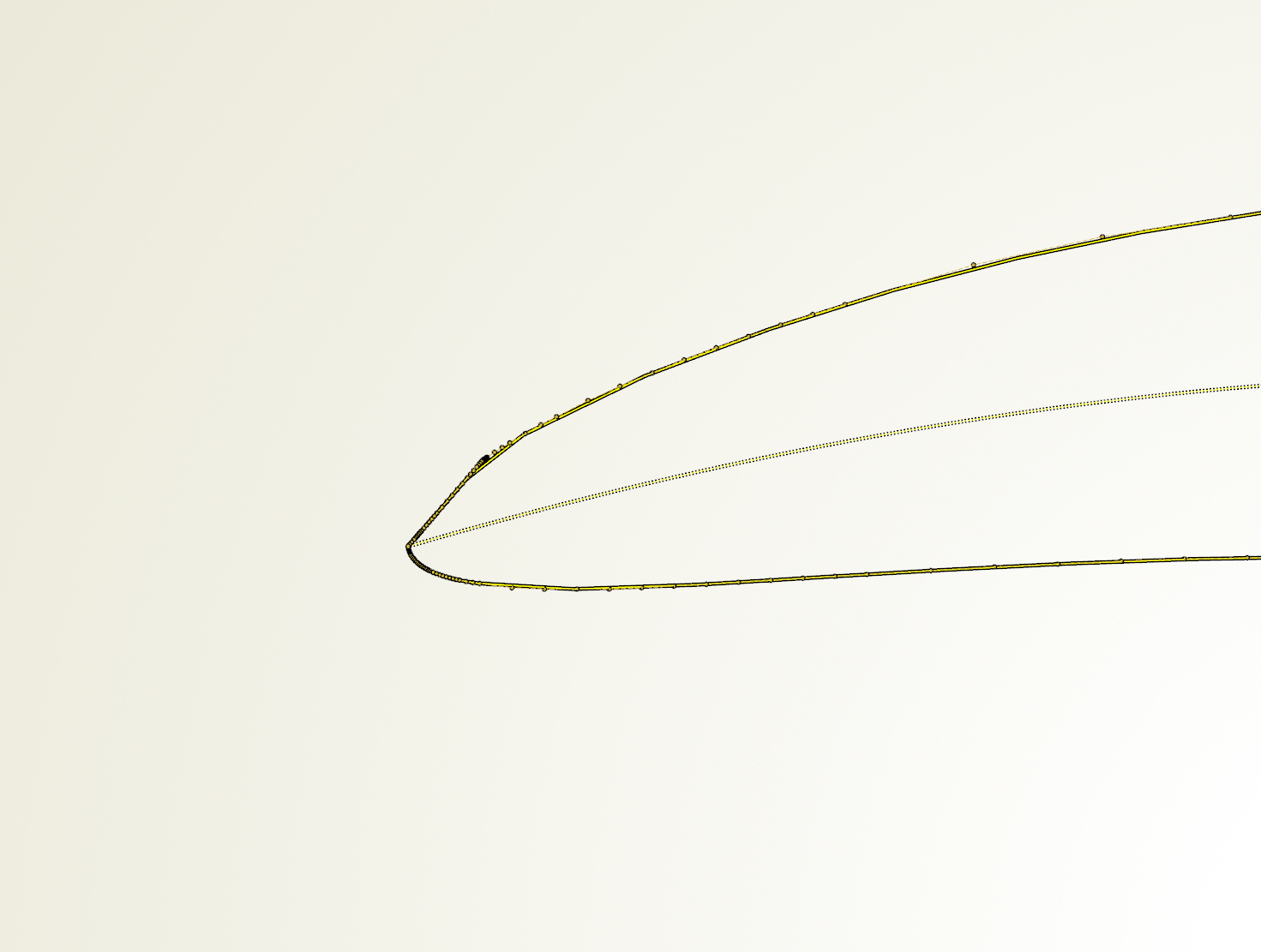
i encountered the same issue and tried several "thickness curves" (the feature definition as well).
Increasing the "Render Resolution" did not solve it at all.
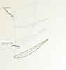
In the attached picture you can see the angular leading edge. The dotted line in the middle is the camberline and the solid line with applied thickness distribution.
---> The points on the solid line are the points of the control polygon, but even the control polygon is angular. <---
Kind regards
Bastian

-
Dear Joerg,
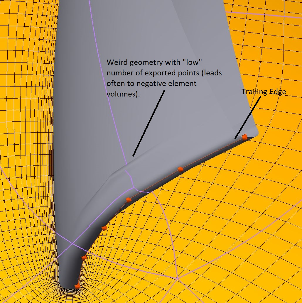
is there a possibility within the export to vary the number of exported points for each section in dependency of the curvature?
When i am exporting a low number of points e.g. 200, the blade looks fine except the trailing edge. It looks very angular and is some kind of partially cropped.
When i am exporting a high number of points e.g. 3000, the entire geometry looks fine but it is really time consuming to export it to turbogrid.
Cheers
Bastian

-
Hi Bastian,
Do you have a simple example (CAESES fdb project etc.)? It should not be a big deal to assign colors to patches, I guess.
How should i share the file with you?
-
Hey Joerg,
my intention is to import the caeses geometry via spaceclaim into ansys mesher. The import of the geometry and named selection by colors works fine with one exception. A single color or named selection is always chosen for the entire solid and not for the intended surface.
I would be grateful for your help.
Cheers
Bastian


Visualization Issue with lines, points, models, etc
in General Modeling
Posted · Report reply
Hi,
Have you toggled any of those filters?
To fit your view, right mouse button and:
Best wishes
Bastian