


Mr. Simone Bigalli
-
Content Count
26 -
Joined
-
Last visited
Posts posted by Mr. Simone Bigalli
-
-
Hi Carsten,
Thank you very much for your reply. I will try to implement these features in my model and let you know if everything worked properly.
Cheers.
Simone
-
Hi,
I’m currently working on the creation of a parametric volute with an overhung section.
I have almost completed my model. However, after having exported my geometry to an external CAD in step format, I noticed that a loss of tangency occurs at the interface between the outlet duct and the scroll, in correspondence of the largest section.
For the creation of the outlet duct, I followed the tutorial available in CAESES: I used the fillet surface (with both tangent factors equal to 1 and edge sampling strategy with 50 nodes) to smoothly connect the outlet section with the scroll, after having defined two auxiliary surfaces.
Is there any correction I can apply to overcome this problem?
Thank you very much.
Cheers.
Simone
-
Hi Joerg,
Thank you very much for your support.
Cheers.
Simone
-
Hi Joerg,
I'm currently working, as part of my PhD work, on the parametric design of compressor volutes. Now that I have managed to obtain a fairly smooth geometry, I wanted to test if I could export it to Siemens NX, which is the CAD we use in my research group and works better with parasolid input files (I tried to import an .igs file, but the result was not satisfactory).
Since we received several partnership proposals from the turbocharger industry, we could be interested in the purchase of the commercial version of CAESES in the near future, and it would be very helpful to know in advance whether this software is able to communicate with our CAD.
Would it be possible to obtain a temporary license (even 1 day only) for the add-on?
Thank you very much.
Cheers.
Simone
-
Hi,
I have read on the forum that there is the possibility to integrate the Parasolid export option in CAESES as an additional component. How can I add it to my current version of the software?
Thank you very much.
Cheers.
Simone
-
Hi Joerg,
Thank you very much for your suggestion, it worked very well!
Cheers.
Simone
-
Hi Joerg,
thank you very much for your reply, the methodology you described will be very useful for my work. Do you know if there's also the possibility, like in the webinar, to exclude the diffuser from the loft, generating a transition from a circular shape to a pseudo-circular one?
Cheers.
Simone
-
Hi,
I’m currently working on the creation of a parametric volute with an overhung section.
Recently I’ve encountered many problems in the creation of the loft connecting the initial section of the volute with the one of the outlet duct, since I’m not able to obtain a smooth transition from a circular shape to an overhung one (of which I attached a picture).
In the last CAESES webinar I attended (Volute Optimization by CAESES + GRIDPRO + TCFD, 5.03.2019), a volute similar to the one I’m working on is shown, where such transition is obtained in a smooth and robust way, and I was wondering how did you manage to achieve it.
Did you connect the two sections by mean of a pseudo-circular section, extrapolated from the overhung one? Or did you use a special loft function embedded in CAESES, capable of automatically excluding the diffuser region from the loft?
Thank you very much.
Cheers.
Simone
-
Hi Ceyhan,
thank you very much for your reply.
Cheers.
Simone
-
Hi Ceyhan and Joerg,
I have anoher question: using the BReps functions and the approach "Fillet between colored faces" is it possible to achieve fillet edges with not constant fillet radius (i.e. with a fillet radius that starts to zero and increase its value linearly)?
I noted there is the possibility to manage this aspect changing the "Type" option in the "Filleting" panel (i.e. selecting "constant distance" or "variable radius" instead of "constant radius") but I don't understand how to use these two different approaches.
Thank you very much.
Cheers.
Simone
-
Hi Ceyhan and Joerg,
thank you very much for your kind reply that allowed me to better understand how to achieve fillet edge between two general surfaces.
Cheers.
Simone
-
Hi,
I have a question about the edge fillet operation inside the BReps functions.
Working with CAESES I noted the possibility to obtain general fillets between two given surfaces using two different options:
- All edges
- Fillet between colored faces
While for simple surfaces I'm able to achieve the desired fillet using the first option (All edges), I have some problems to obtain the same result using the second one (Fillet between colored faces). In other words I don't understand how to use correctly the edge fillet operation by means of the option "Fillet between colored faces".
To explain my question I attached a simple example; could someone explain me how to resolve this problem?
Moreover, I would like to know if CAESES offers other options to quickly obtain general fillets between two given surfaces.
Thank tou very much.
Cheers.
Simone
-
Hi Joerg,
thank you very much for your kind reply. I'll try to find another way to obtain my final geometry.
Cheers.
Simone
-
Hi Jeorg,
the problem is due to the fact that, in my project, the final line is not fixed: therefore the end angle of my surface of revolution should be variable with the final line position.
In other words, at the moment I chose an end angle of the surface of revolution that allows reaching my final line but, when the final line changes, also the end angle has to change in order to obtain the desired surface of revolution. Moreover it is not possible to parametrize the end angle in order to follow the variations of the final line position.
If it would be possible to define a surface of revolution simply using the original and final line (without defining an end angle) the CAD should be more stable.
I'm not sure I was clear enough (I hope so). :-)
Thank you very much.
Simone
-
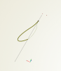
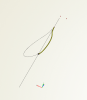
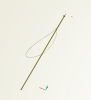
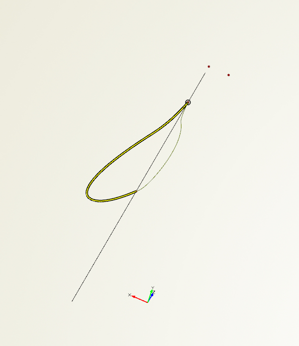
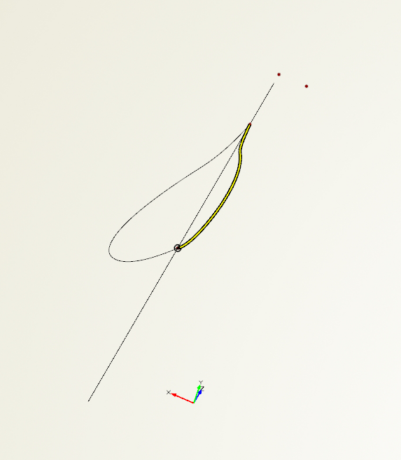
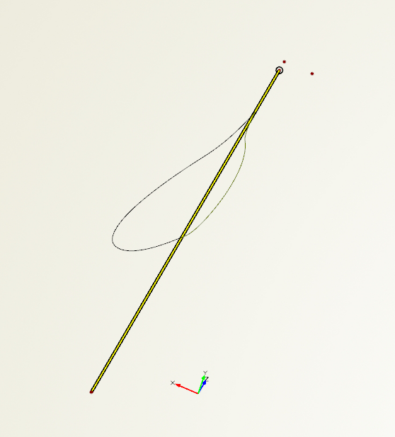
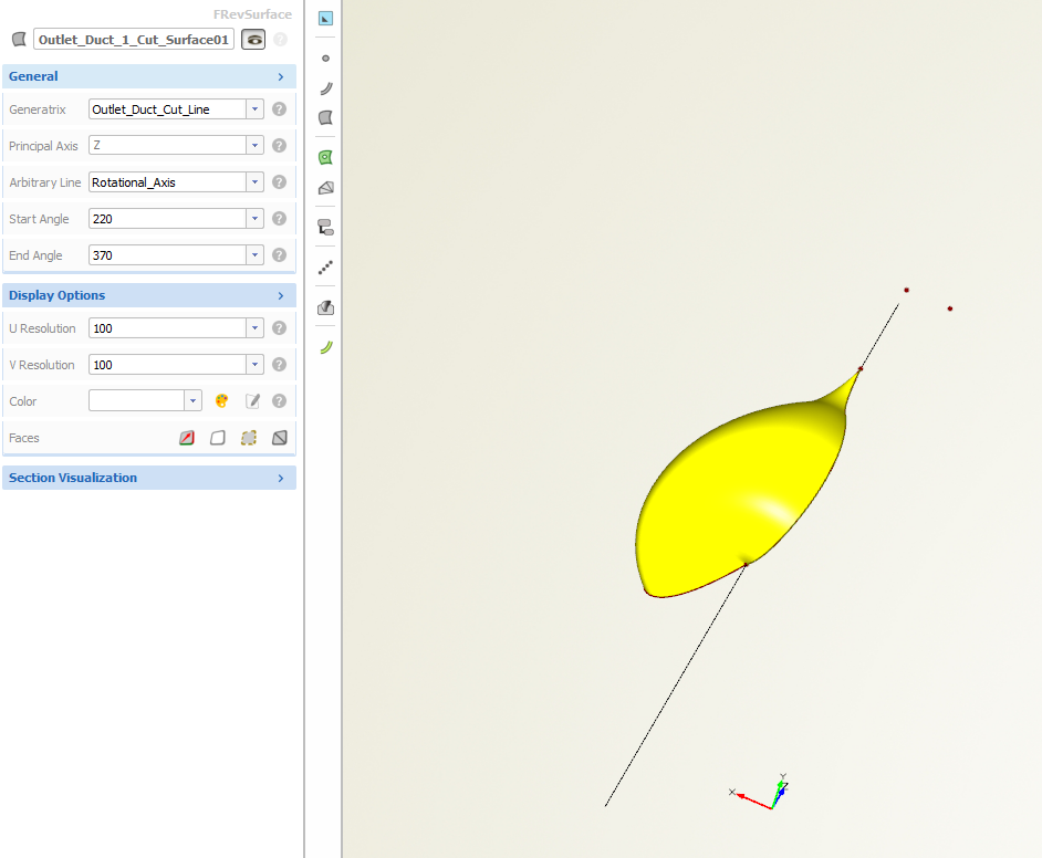
Hi Joerg,
you'll find attached some pictures to clarify my question.
I would like to achieve a surface of revolution from a generatrix line (figure Generatrix_Line) to a final line (figure Final_Line) using the revolution axis shown in figure Revolution_Axis. At the moment I achieve this surface fixing the start angle and the final angle (figure Surface_of_Revolution); I would like to know if is it possible to obtain the same result only defining the original line and the final one (without defining the start and the final angle). This approach could give me a better parametrization.
Thank you very much for your answer.
Simone
-
Hi,
is it possible to create a surface of revolution that starts from a generatrix line and reaches another fixed line or surface? From the surface of revolution panel seems to be possibile to obtain a surface of revolution only starting by a genaritrix line and fixing the start angle and end angle, is it?
Thank you.
Simone
-
Hi Joerg,
thank you very much for your quick reply.
Cheers
Simone
-
Hi,
I would like to ask if in addition to the B-Spline surfaces is it possible to obtain also Bezier surfaces in CAESES.
Thanks.
Cheers.
Simone
-
Hi Ceyhan,
thank you very much for your answer. I'll start with the tutorial you recommended.
Cheers.
Simone
-
Hi,
I'm working on the creation of a parametric volute with a generic section (using B-spline functions) and I try to undertand if it is possible to obtain it in Caeses without external software (like for example Matlab).
In fact, in order to connect the control points positions (x,y,z) of the B-spline to the sections area (with the goal to control the area distributions), I need to use 'while' cycles. Is it possible to insert these loop in the program for the full parametrization of the geometry? Are there any examples or tutorials useful to understand how to program in Caeses?
Thanks.
Simone
-
Hi Joerg,
I understand. Thank you very much for your answers and for the assistance to solve my problem.
Cheers.
Simone
-
Hi Joerg,
thank you very much for your assistance. Now all seems to be ok.
However I have another doubt. Do you have any idea on why in the example I attached on I was not be able to calculate the area of the B-Spline c1 using the wrong plane but I was able to evaluate in the correct manner the area of the ellipse c2? In fact, yesterday I didn't understand why, using the same settings, I was able to calculate the correct area for the ellipse but I was not be able to obtain the same result for the B-spline.
Thank you very much for your reply.
Simone
-
Hi Joerg,
I attached an example of the file Caeses I'm working on.
This is the script:
// **********************************************************************
// Autogenerated by CAESES 4.3.1
// Date: mar set 4 2018
// **********************************************************************
bsplinecurve c1()
ellipse c2()
point p1()
point p2()
point p3()
point p4()
point p5()
point p6()
// **********************************************************************
c1.setWeights([1, 1, 1, 1, 1, 1, 1])
c1.setKnotvector([0, 0, 0, 0, 0.25, 0.5, 0.75, 1, 1, 1, 1])
c1.setPL([p1, p6, p3, p2, p4, p5, p1])
c1.setMappingValue("torsion")
c2.setConstantAngleSpeed(false)
c2.setAxisB(1.832)
p1.setX(1)
p2.setX(-1)
p3.setX(-0.82)
p3.setY(2)
p4.setX(-0.82)
p4.setY(-2)
p5.setX(0.82)
p5.setY(-2)
p6.setX(0.82)
p6.setY(2)
point p(0, c2.getArea(0, 0, -1, 1), 0)
point r(0, c1.getArea(0, 0, 0, 1), 0)
Thank you very much for your reply.
Simone.
-
Hi,
I have a question about the evaluation of the area of a generic section.
I would like to know if it is possible to extract the global area of a closed B-Spline using the command section.getArea. I tried to obtain this for a generic section I'm working on. However, when I did so, I obtained zero as a result.
Thanks.
Simone
Area and COA calculation on custom plane
in General Modeling
Posted · Report reply
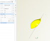
Hi,
I'm trying to evaluate the Area and COA of a curve drawn on a plane different from the principal ones. However, the two functions getArea() and getCOA() available on CAESES seems to work only on principal planes.
Is there any workaround?
Thank you very much.
Cheers.
Simone