


Mr. Chien Nguyen
-
Content Count
24 -
Joined
-
Last visited
Posts posted by Mr. Chien Nguyen
-
-
Dear Heinrich and Paulo
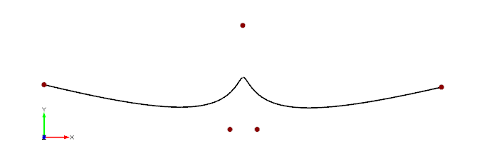
Thanks so much for your answer, I upload my project here. if i just create 1 fillet radius (60) with fillet edge, it works very well. Now I would like to create one fillet radius 50 at Pitch side and 60 at Back side. I tried but it did not work
Beside, could you explain the meaning of position value, I understood that it should be from 0 to 1, but what is the position of 0 and 1
Thank you so much
-
Dear Heinrich
Thank you so much for your answer. But I tried with the sample propeller file in Caeses, I still did not succeed to create the fillet!
is this possible that you can upload for your file for my reference ?
-
Hello,
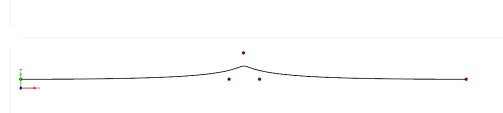
Is this possible to create variable fillet at propeller root? Normally, at the propeller root there are two fillet radius parameter (one at the pitch side and the other at the back side)
For the 1 radius fillet, I can do it well with brep edge fillet. I tried to create variable fillet with surface mapping but it does not work!
Thank you
-
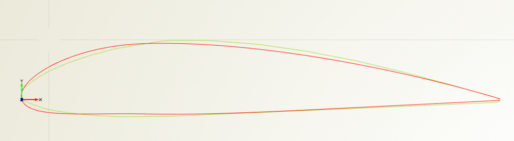
On 10/26/2020 at 3:48 PM, Mr. Heinrich von Zadow said:Dear Chien,
it looks like the maximum thickness position of the red profile is a bit too far towards the leading edge. However, the green profile also looks a bit "different" to my eye, so I doubt that you will get a much better fit when sticking to the NACA4DS. You could try to adjust the design variables manually for one of the sections just to get an idea if there is a lot of room for improvement.
About the "weighting":
In the feature I gave to you earlier, I simply check for the maximum deviation between points and profile like this:genericcurve errorFunction(){ .setx(t) .sety(profile.getShortestDistanceSquared(linearInterpolation.getpos(t))) .setz(0) } parameter error(errorFunction.getMax(1))If we assume that your profile starts at t=0 (trailing edge, suction side), then goes through t=0.5 (leading edge) and back to t=1 (trailing edge, pressure side), you could put more "weight" to the leading edge region as follows:
1. You define a "weight distribution"
--> it's just a function running from x=0 to x=1 with it's maximum at x=0.5.
2. you multiply each squared error with the corresponding evaluation of the weight distribution. The generic curve should the read like this:
.sety(profile.getShortestDistanceSquared(linearInterpolation.getpos(t))*weightFunction.getPos(t):y)3. Instead of just checking for the maximum quadratic error like before, you now use the area below the error function as objective measure for your optimization:
parameter error(errorFunction.getArea(0,2))You can play around and tweak things by manually adjusting the shape of the weight function. E.g. if you want to emphasize both, the leading and trailing edge region, your function could look like this:
The old fitting result of my example looked like this (green: original, red: fit):
now, with the weighting included, it looks like this:
Keep in mind, that the result will always be only as good as the ability of your parametric profile to conform to your given data... I attached the project file for your convenience.
Best regards,
Heinrich
Dear Heinrich,
Thanks so much for your file. I am able to use it on my project. But it did not change much the result I got without weight function. Maybe you are right, using NACA4DS may not get better result.
Do you have suggestion about changing to another parametric airfoil ?
All the best
Chien
-
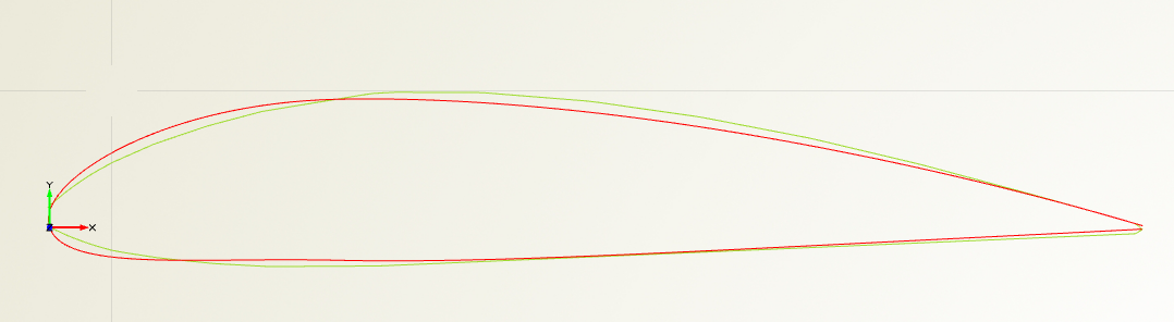
On 10/20/2020 at 2:15 PM, Mr. Heinrich von Zadow said:Dear Chien,
from the picture it looks, as if you have an angle of attack unequal to zero. My suggestion would be to extract this value and rotate the profile such that the leading and trailing edge both have a y equal to 0. Let's see how this turns out -- my feeling is, that this should also reduce the large amount of camber you see in the red profile right now.
Cheers,
Heinrich
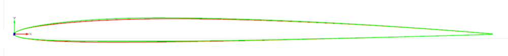
Dear Heinrich,
Thank you so much for your advice, I am able to get better result (see the picture below). (the red curve is the Naca4ds and the green one is the original one)
Now I just need to adjust the leading edge to get much better result ? But I still do not know how to adjust the error function to get much better result? Can you show my some ideas ? Thank you
Chien
-
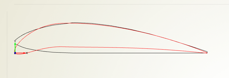
Dear Heinrich,
Thanks so much for your reply.
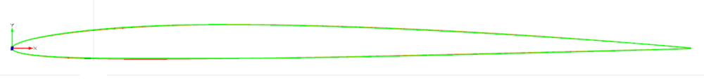
I have managed to import my data points and got the result as a picture below. The red curve is the Naca4ds after 100 iteration and the black one is the original profile from data points.
However as you said, I did not get good result at leading and trailing edge. I realized that at x = 0 and x = profile length, the y value of the Naca4Ds profile is also 0. But for the original profile, those y values are not 0.So that, it is impossible to get a good approximation Naca4ds curve to the original profile.
I am thinking to apply a deformation(or a deformation function, or something similar) to the Naca4Ds at leading and trailing edge to get the shape of original profile. How do you think ?
Thank you
-
Hello,
My problem is that I am having a set of blade section from 0.2R to 0.95R with data points for each sections. Basically, I can model the propeller from those sections by lofting a surface through all the sections.
But now, I would like to fit a mathematic function to all the blade sections to create a parametric profile then put it in a curve engine for propeller modelling.
For example, fitting a mathematic function to the Wageningen propeller sections. Is there anyway in Caeses that can do this ?
I am thinking to start with the Naca profile then using optimization algorithm to find the value of c, m and p that creates the sets of sections which are best match with the sections from data points (for example the maximum distance is less than a define limit)
-
Dear Chien,
one of the files (with number "2" and "NO_REBUILD") in the name shows nothing but a hub. The other file doesn't show anything. Please take some time to prepare the files and let me know in detail for which object the BRep operation fails.
Maybe you can also use just one string parameter to hold the file path so that I can adjust this one parameter to my local directory of csv files.
Thanks,
Heinrich
Dear Heinrich,
Sorry for make you confused!
I have uploaded file again. Please change the location of "CSVData" folder in the string parameter "csv_loc". In my case, I put the "CSVData" folder in D:\
My final Brep is "Prop_Hub". It is fail to create fillet in the "NO REBUILD" file and fail to make solid in "REBUILD" file. Maybe you can just have a look at it to save your time. Thank you so much!!
Chien
-
Dear Chien,
you can upload your file here:
https://fcloud.friendship-systems.de/index.php/s/95ryLm88sAkp8Cx
It's an upload only link.
Cheers,
Heinrich
Dear Heinrich,
I have uploaded the files.
There are 2 files and data points (csv) file for section. Maybe you have to manually load the section data
The first file (No rebuild section) I have a problem to create fillet with hub and blade
The second file (rebuilt section) I have a problem to create solid from intersection between blade and hub
Thank you so much!
Chien
-
Dear Chien,
that's hard to answer -- maybe you can compare how things are done in the propeller sample that comes with CAESES? Or, if you are willing to share your project, I can take a quick look.
Cheers,
Heinrich
Dear Heinrich
Can I send my project to you by email ? Thank you
-
Dear Heinrich,
Thank you for your reply!I have made the generic curve from the section curve and choose 10 control points for generate nurbs curve. The blade is now more smooth! I have used Blade tip feature to create the blade tip. But I have problem when I try to make a solid propeller. When I create Brep with "solid from intersection" option for Hub and Blades, there is only Hub part left....
How can I do in this situation ?
Thank you!
-
Is there any way to rebuild a interpolation 2D curve through the imported data points to Nurbs curve or Fspline curve (similar to rebuild command in Rhinoceros) ?
I am having the problem creating loft surface through profile sections to make a propeller blade. The imported sections have too many points, so the lofted surface is not good and my computer takes a lot of time to re-create the surface when I change the parameters (such as diameter). So I think the problem is the sections have too many points. I would like to simplify them by Nurbs curve or Fspline curve, then it's possible that the problem can be solved.
I can do this manually for each sections but is there any better way to do ? (I am thinking about something similar to the command like Rebuild in Rhinoceros)
Thank you!
-
Hi Chien,
the way I understand it, the FEzHull is more like some sort of container to gather relevant geometry data and export to EzGraph. You could probably just start with an imported geometry, e.g. KCS.
Cheers,
Heinrich
Dear Heinrich,
So i misunderstand this feature, I think it is a way to generate ship hull quickly :). By the way, from the tutorial, I know to create the simple fully parametric hull form. Now I have a 3d hull form in iges and stl format, I would like to remodel it in Caeses to create fully parametric model. My question is that how I compare the hull form in Caeses with the original igs hull form to make sure I do correctly. I am thinking about to compare 2D section. What is your recommendation ?
Thank you
-
Hi Chien,
maybe you can start by taking a look at the type documentation. You find it by clicking the icon next to any objects name (see screenshot).
 Annotation 2020-02-13 131415.png
Cheers,
Heinrich
Dear Heinrich,
Thank you for your help! I will try to start with that! By the way, do you have a sample file that uses Ezhull to create a hull form
-
Hello,
I tried to find the topic about how to use Ezhull (In Caeses go to Cad - Ezhull) in Caeses but I cannot find anything
Could you please show me how to use or give me the example of the hull created by this feature
Thank you!
-
Hi Chien,
Sorry for the late reply, I was on vacation.
Can you please send your project to erdem@friendship-systems.com, so that I can give a look?
Cheers
Ceyhan
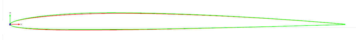
Dear Ceyhan,
I have managed to create parametric Gawn propeller. The result looks quite good (see attached picture)
However, I have a question related to profile section ( I have sent you an email)

Thanks again for your help
-
Hi Chien,
Please find the attached simple project.
This might give you some idea about how the operations are defined. Besides that please check the sample "Axial Fan" under Documentation>Samples
For three airfoil sections, I have defined chord scaling, pitch, yaw and rake. This is just for illustration purposes to show how the steps are performed.
Of course you would like to perform those steps not one by one but using a Feature Definition, and as a result obtaining a Meta Surface.
Note: I have figured some errors in the code that I have attached earlier which are corrected
Cheers
Ceyhan
Dear Ceyhan,
Thank you very much for your help,
Now I am able to do well. However, I have a question related to propeller tip. There is a feature definition namely " Blade tip", but I cannot use in this case because the generated surface is not FgenericBlade
How can I do the blade tip in this case. It is quite a challenge because the tip is only 1 point with thickness
Thank you
-
Hi Chien,
Under Documentation Browser > Samples;
there is the Propeller Setup example. I will strongly recommend you to check the mentioned model and go over the Curve Engine, Meta Surface tutorials.
If you have any further questions, please do not hesitate to ask.
Cheers
Ceyhan
Dear Ceyhan,
I have gone through the Propeller Setup and blade tutorial. In these two examples, the Generic Blade is used. So everything like Pitch, Rake, Skew is already set up in the black box. So in case if I have separated data points of profile, I have to do everything like Pitch, rake, skew manually.Is it right ?
-
Hi Chien,
If you replace the translation to cylindrical transformation within the feature you can reach your goal. Maybe you would also be interested to introduce some skew pitch rake and scaling beforehand.
The Loft method within CAESES is a tight method.
Cheers
Ceyhan
Hello Ceyhan,
Is there a quick way to add pitch, rake and skew for profile transformation, or I have to do it manually by creating Caeses feature
Thank you!
-
By the way, I think I will do cylindrical transformation for 2d profiles then create a loft surface through the 3d profiles.
I would like to ask the loft method in Caeses is tight loft or loose loft ( these are some terms in Rhinoceros), because I want to make sure the blade surface match with the profile
Thank you
-
Hi Chien,
Maybe you should start with a feature that reads your profiles.
Please check the attached simple project that reads airfoil data. Afterwards you can go over tutorial files that would improve your CAESES capabilities.
Cheers
Ceyhan
Thank you! I think now I know how to do
-
Hello, I would liketo use the profiles from some propeller series such as Gawn, Wageningen...Hi Chien,
Would you like to use some profiles from a certain database for each section or use some Naca variations?
Cheers
Ceyhan
I think for such series, we cannot use Generic Blade in Caeses. But I do not know how to do. I know I can use the online Wageningen tool, but it is a black box and I would like how to do it in Caeses and then I can do for other series!
I do not know is it possible for Caeses can share their Wageningen file
-
Hello,
from the tutorial, I know how to create the propeller with Naca profile.
However, I would like to model the propeller with 2d profile for each radius (0.2R, 0.3R... 0.9R)
How can I do it in Caeses ?
I have watched the video about Wageningen series propeller with Caeses, It looks like you are using custom profile for each radius
Thanks in advance


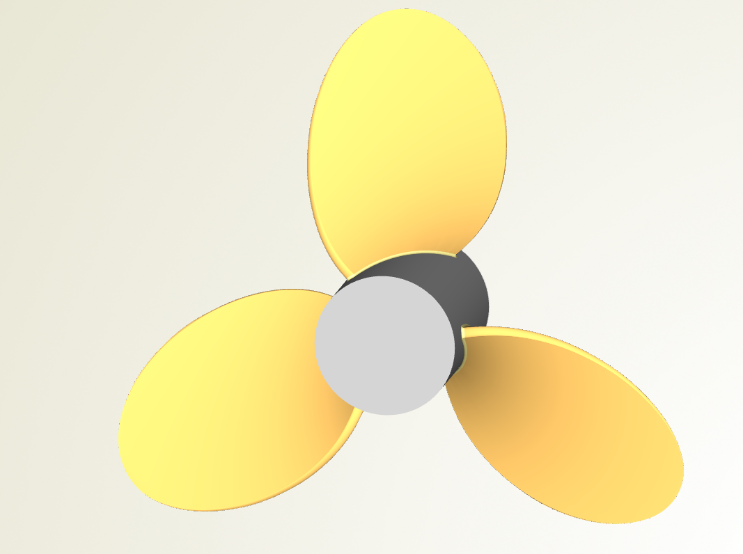
Variable fillet at Propeller Root
in General Modeling
Posted · Report reply
Dear Heinrich
Thanks for your reply and your correction. I will try to play with it to get the variable fillet and let you know if it works