


Mr. Klaus Straka
-
Content Count
9 -
Joined
-
Last visited
Posts posted by Mr. Klaus Straka
-
-
Hi Joerg,
nice video, thank you :) . I try to reformulate my question.
Actually the project i attached in my last post was my first try to check if i can control the rotation of a conture along a sweep path and, although my solution was not as fancy as yours, it worked.
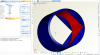
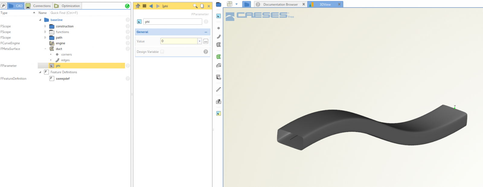
If the parameter phi is set to zero the conture at the beginning of the path has exactly the same orientation as at the end. If phi is set to 90° the conture is twisted. So far, so good.
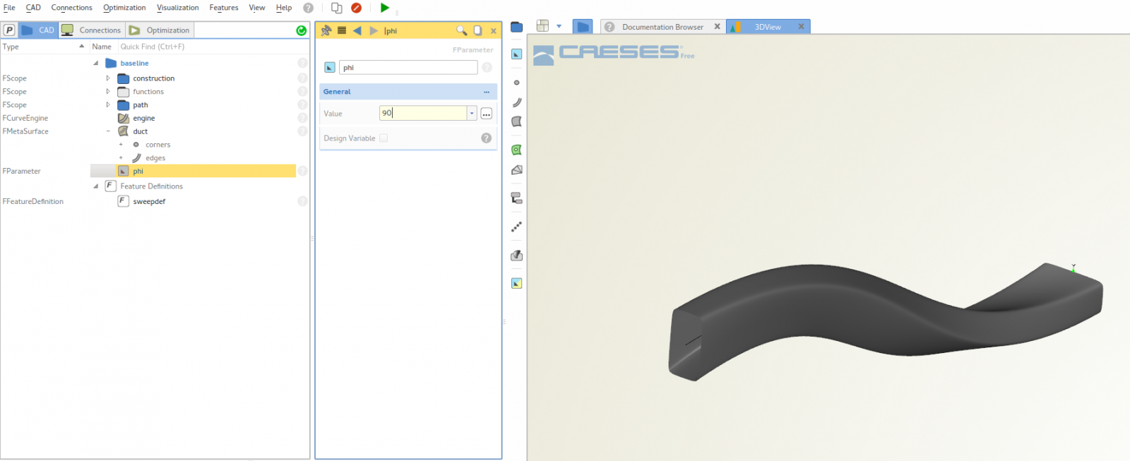
However, if i apply the sweeping to a helical path (see. post #3) the conture rotates during the sweep transformation (not very sure but i think it rotates around the tangent vector of the path) even if i don't set any rotational transformation. That's what i tried to explain in the first picture in post #3. In other words: With the finding from my example above i was in the opinion that the orientation of the sweep conture is exactly the same at the beginning and the end of the helical path (as long as the helix angle at the end is a multiple of 360°). However, this is clearly not case :unsure:
The question is now: what is the reason for this behavior?
Hope its more clear now,
Thanks for your help and have a nice weekend,
Klaus
-
Hi Jörg,
thanks for your reply. I already played around with the "Sweep Transformation" and tried to control the rotation before my previous post. I attach a small project which is based on the Sweep Transformation Tutorial and where the sweep conture i twisted during the transformation. In the screenshots you can see that for this planar sweep path the conture is not rotated if the angle phi is set to zero.

If phi is set to 90 degree, then the conture is rotated as expected.

However, if the sweep path is not planar but a a curve in 3D space, then i get the unwanted rotation mentioned in my previous post. Can you give me some idea what the reason for this rotation is. Hopefully it is than more easy to compensate this behaviour.
Thanks again and best regards,
Klaus
-
Hi Willy,
i have a question on a similar topic like Barmi. I want to sweep a profile along a helical path and at the same time keep a certain orientation of the profile. The goal is to use this sweep transformation to create a meta surface as describes in the "Sweep Transformation" tutorial.
The screen shot below shows the result of the profile movement with the sweep transformation. The transformed profile is somehow rotated along the path.
 However, for me it is important that the two parallel edges of the profile always stay in direction of the z-axis as shown in the following screenhot.
 For the transformation in the latter picture i used a translation (as you decribed above) and a rotation. However, i wonder if this type of transformation gives me the possibility to create a meta surface via the curve engine. I far as i understood i have to use the sweep transformation in this case. Right?Is there a possibilty to control the rotation of the profile along the path when performing a sweep transformation?I attach a small example project with witch the screenshots have been created. Maybe it helps ;)Many thank for your help and best regards,Klaus
 -
He guys,
many thanks for your quick response, i'll try v.4.2.1.
Cheers,
Klaus
-
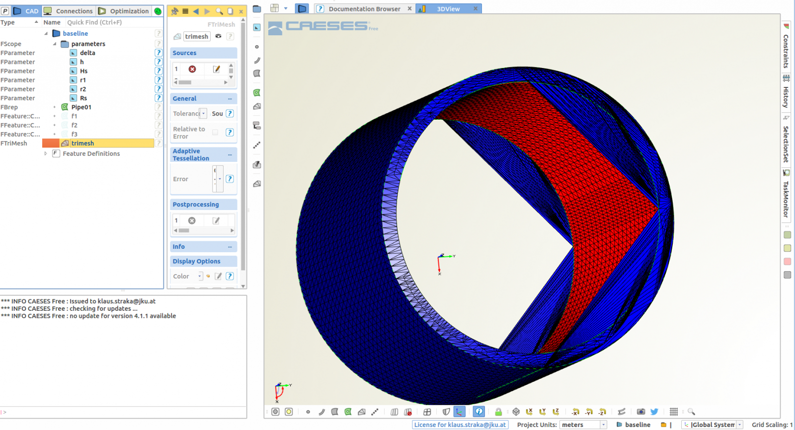
Hi,
i just tried to create a simple pipe by a boolean operation of two cylinders. However, the result look a bit ugly. I added a trimesh for a better visibility of the degenerated geometry, please see the attached screenshot. Moreover i added the project file - i want to subtract cylinder f2 from cylinder f1.
In the past i got such degenerated geometries if the object i subtracted had exactly the same height, thus, f2 is slightly higher than f1. But this doesn't help in this case. Any suggestions? I use CASES Free 4.1.1 on Ubuntu.
cheers,
Klaus
-
Hi Arne,
thanks for your quick reply. I will try your approach.
Cheers,
Klaus
-
Hi,
i am working on a feature that actually draw some helical curves and circles. Therefor i frequently have to calulate an angle in the x-y-plane. Ok, thats easy. To get the right actual angle in the range of 0-360 degrees it wrote a function
function quadrantCorrection(FPoint startp, FDouble phi):FDouble
  if (AND(startp.getY()>=0,startp.getX()<0)) // 2th. Q.
    phi = 180-phi
  elseif (AND(startp.getY()>=0,startp.getX()>=0)) // 1st Q.
    phi = phi
  elseif (AND(startp.getY()<0,startp.getX()>=0)) // 4nd. Q.
    echo("Q4, phi " + phi)
    phi = 360-phi
    echo("Q4, phiCorr " + phi)
  elseif (AND(startp.getY()<0,startp.getX()<0)) // 3rd. Q.
    phi = 180+phi
  endif
  return(phi)
endfunction
I use this function for a great number of times and it seems to work fine. However in the attached project in the feature definition "MixerBasemesh" at line 340 it fails for whatever reason.
Below some debug output is given, the x and y coordinate show that the point is located in 4th quadrant. The function above detects this correctly (indicated by the debug output "Q4, phi 7.44226") but it does not compensate (phi=360-phi) the angle as shown by "Q4, phiCorr 7.44226".
phiE: 7.44226
x: 19.9307
y: -2.60349
Q4, phi 7.44226
Q4, phiCorr 7.44226
phiECorr: 7.44226
phi: -37.5577
phi: -37.5577
-----
This is a somwhat strange behaviour, i have no idea what i am doing wrong. Any comments on this.
I use V4.1.0 on Ubuntu.
Thank you for your help an best regards,
Klaus
-
Hi,
it is quite easy to set solid names in stl-files. Just create a new color and assigne the solid name to the color, let's say "inlet". Then set the color of the inlet patch to the color "inlet" and export STL(Multi Body). Now the stl-file looks like this:
solid inlet
facet normal 0.0182022738298 -0.999834321385 8.37095476786e-05
outer loop
vertex 0.107793885811 -8.99435408899 0.638042712216
vertex 0.210288153997 -8.99254157023 ....However, there are some small drawbacks, seems like you cannot assigne the same name to a geometry object and a color.
Cheers,
Klaus

angle between two arbitrary lines
in General Modeling
Posted · Report reply
Hi Burak,
you can use the tangent vectors of the two lines to calculate the angle by means of the dot product. I attached a small example. Hope this helps.
Cheers,
Klaus
calcAngle.fdbc