


Mr. Bram1 Kerkhofs1
-
Content Count
26 -
Joined
-
Last visited
Posts posted by Mr. Bram1 Kerkhofs1
-
-
Hi
Edit: It is version 4.4.1, appologies
I'm having a problem with the new version of Caeses.
so this code doesn't compile:
imagecurve interpolCirccurve()
interpolCirccurve{
.Setcurve(Curve)
.setDomain([0.5,1])
.setName("halfCurve")
.SetVisible(0)
}
it reports:
"Error: Line 112 [1,19]: Scopes not allowed inside functions
"
So the reason why I program like this is: when you have an if-statement, and you want to declare the "curve", but "if blablabla, take curve. Else take curve1" or something alike. When I declare the image curve twice, I get a warning that stuff is declared mutliple times. So this is a way to ommit the warning.
Any suggestions how to do this in the new version?
Cheers!
Bram
-
Hi Bodo
Thanks, your solution did help me the libpng12-error
I also needed to install the canberra-gtk-module, by simply doing sudo apt install canberra-gtk-module
Afterwards I had a problem with the licensing: it returned the error:
The license file contains hardware keys not corresponding to this workstation.
Please send us an email with the failed identifiers!
So i tried to start caeses by "./CAESES -resetauth"
But it didn't work out. So Joerg, here comes my e-mail :).Regards
Bram
-
Hi Joerg
No problem,Thanks for the tip!
If I can make the drawing to scale, that would be already good :).
I put a working case in the attachment.
It basically gets all the lines from a brep and puts them in FGIGeometries and loads them into the screen.
Note: The input breps must be in between square brackets (as an objectlist)
Cheers
Bram
-
Hi
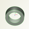
I was busy with checking if I could make a technical drawing from a brep.
In attachment I put a shape, and I would like to make a drawing out of it.
I tried to experiment with the 2D window a bit, and also with the FGIGeometry's that you get, but for now I can only make a drawing from a line, not from a surface or a brep.
Anybody an idea?
Thanks
Bram
-
Hi
The most easy way I found is by the use of the getTan() command. It returns the angle that a tangent line would make with a chosen general reference plane (X-plane, Y-Plane or Z-plane). You can use the angle of the GetTan() to make a rotation of your chosen surface around the Origine. Translate it than to the place where it needs to be.
When you have a surface, you first need to make a SurfaceCurve, which goes through the location you want to make a tangential plane. Than continue with the getTan() command.If anyone has a better solution, please fill in :)
Bram
-
Hi
I'm trying to make a plane tangent to a curve. If for instance, I could use the normal vector of the curve and set it as the normal vector of the plane (which is a surface).
I was checking out the Matrix4 transformation, but it didn't work.
does anyone have an idea how to copy orientations easily? Or a way so you can make objects parallel or perpenidcular (or with a certain angle) relatively to each other?Have a nice holliday
Cheers
Bram
-
Xavier
Stl does the trick as Joerg mentioned.
Personally I already 3D printed some stuff with Caeses.
I have the experience that it is way easier to control the tesselation with breps than with a solid a tesselation object. So you can control the 'triangle' size in the breps. Here under are the parameters I adjust:.setAngleToleranceInDegrees(AngleTolRough)
.setChordHeightTolerance(ToleranceRough)
.setMax3DEdgeLength(MaxEdgeRough)
as you can see that the part of the 3D printed model that had the above parameters could be done with rough (large) triangles. The AngleTolRough and other parameters are defined globally.
When I combine all my different parts in a brep with a boolean 'union' operation. Don't define any of the above mentioned parameters or you will overwrite them for the whole brep.
Load this brep as a source for a solid. Do some post processing ( e.g. delete too small triangles, etc etc). Use this solid afterwards to be exported to an stl.
I did some printing and this method worked nicely. I used half of the precision of the printer as a maximum value for the Max3DEdgeLength. The ChordHeightTolerance is the tolerance it can deviate from the mathematical place, I used 0.1*precision of the printer. The angelToleranceInDegrees is the maximal angle whish is allowed between two triangles, which I take as 10 degrees.
You'll see that the Max3DEgdeLength will reeeaaaally make your stl file large :).
Hope my reply wasn't too late :).
B
-
Hi Joerg
How do you make those cool renders with Caeses?
Cheers
-
Hi Stefan
Thanks!
What is the difference between using the "fp_" prefix and the "FFeature::" ?
Is it the same as when you use "point" you generate a "3DPoint" object? When do you use which one?
cheers
Bram
-
Hi Joerg
I didn't know you could make different instances of the Brep-operations. looks nice! thanks!
What is the result of the 'type provider' in the 'attributes' menu of the feature definition? All my feature definitions have the generic mark in front and these have the Breps mark.
-
Hi Jaap
As I understand your situation: you have an arbitrary surface, and you want to make it into a solid with a certain thickness.
If the innerside of the surface didn't matter, I would use the "Extrude edges to plane" function of the breps.
since it is a arbitrary surface you probably are best off with the offset surface, or just use an image surface and translate it, depending on what kind of edge you want. The offset surface will result in edges with a straight angle, the image surface will result in edges which go in the direction of the translation. The remaining part is to get those surfaces connected.
In any case I would advise to use breps for the connecting part. Add the two surfaces (original - offset, or original - image) to the sources and add the operation "Close planar holes" or "Close non-planar holes". This normally does the trick. You can If these commands don't work, try the "faces from planar curves" and use the edges of the surfaces.
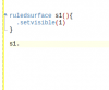
If this doesn't help because of reasons, you can always use the ruled surface. But bear in mind that the orientation of your edges need to be correct: use the edge or the ReversedEdge. If this isn't making your edge as you want you can use 'fillet surface'. And of course if you want complete freedom: make a metasurface out of it.
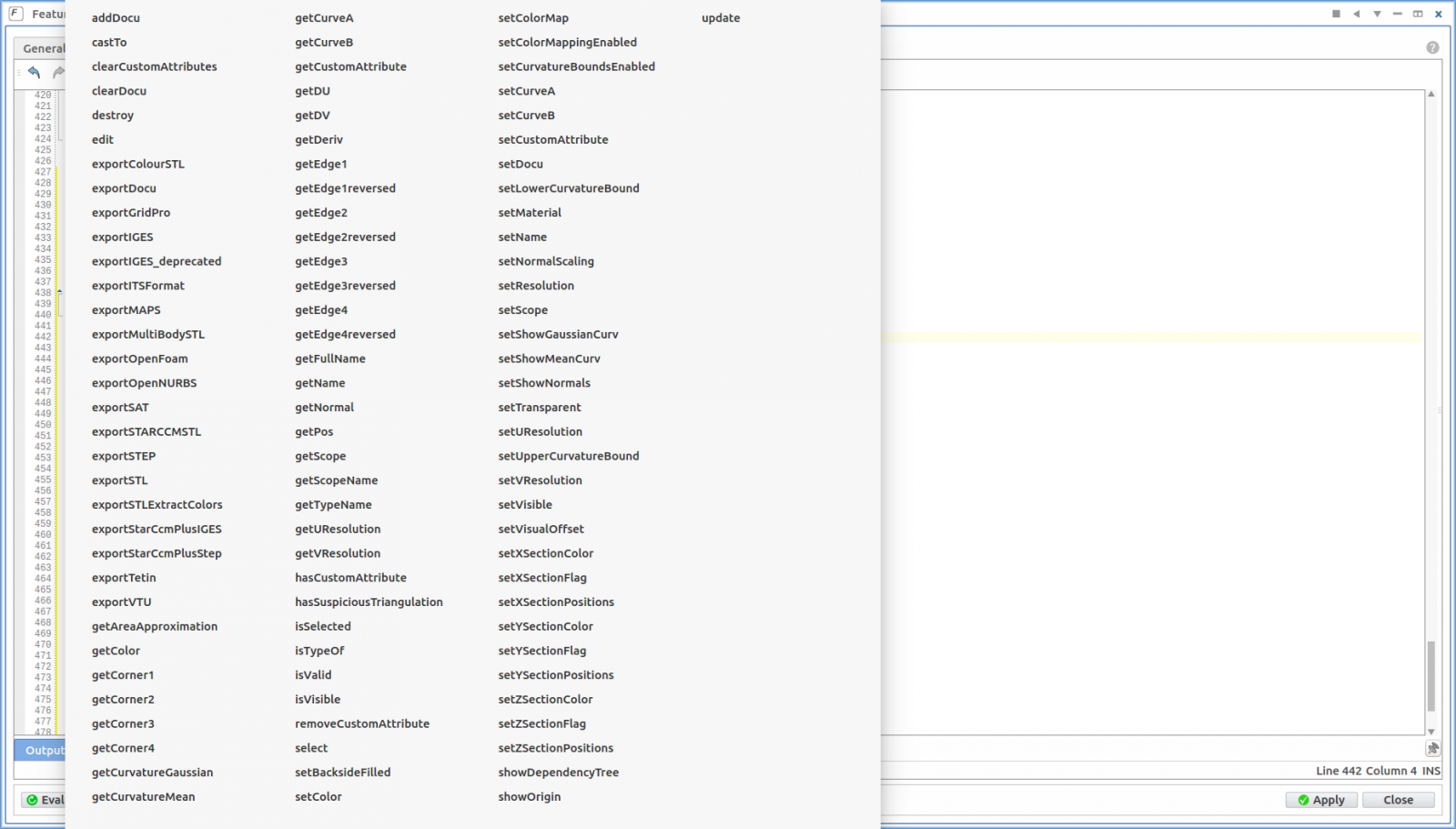
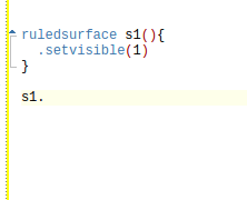
In order to learn the command to get the edges of existing surface or breps, I would advise to get working with featureDefinitions. You can use these commands also in the input screens of the objects in the object tree. Select the two surfaces from here above and right hand click, select 'create feature def". Open your feature definition. get on a new line, type the name of a thing that you created in there (for the surfaces above, probably one is called "s1") add a dot "." and press "ctrl + space" and see all the options available. This is how I discovered what all is possible.
side note:If the brep doesn't seem to be responding to your commands, or the system crashes, it has to do that you made a circular reference: you are defining things based on the thing which is being defined. This sometimes happens when you refer to edges of the brep which you are currently defining. Just make a new brep and add the first one as a source. Then do the operation.
If your brep only has green edges, it means it is closed and you can export it right away as an stl. you can use the Display options: Chord height, angle tolerance and 3D max length in order to control the tesselation and accuracy of the model. Don't forget to put the "face display" on "face triangles", it shows you the triangles :). you can also use the brep as an input for the solid.
In order to modify with complete freedom your nurbs-surface I have the following 3-part strategy (I'm not claiming it's the best, but it works):
Part 1:
Make a feature definition: with following input: nurbs surface points of sampling in each direction.
Let the feature definition do the following: sample some points (let's say 10 in each direction, so a 100 in total), check with a new nurbs surface, with these points as input, if it approximates your new surface sufficiently. if so that is where part 1 ends. This is your base line.Part 2:
create an object of this feature definition and look at that beauty. right click on it and select 'detach'. This will take a while, but it is making all your points accessible for adaptation from the interface.
Part3:
Create a new nurbs-surface with the points as an input. Since you can still adapt the points as you want the new surface will follow.The above gives you complete freedom of the shape, if your adaptations are always the same or less 'intuitive' as here above you can automate it all in the feature definition. If meant by "adapting the surface" as in: put a new in, you just need to make this an input argument of your feature definition :).
Hope this helps you.
Kind regards
Bram

-
Hi there
When I construct a fobjectlist which contains my own defined FeatureDef's, I can't (don't know how to) cast them to the FeatureDef when I want to retrieve the item.
The name of my FeatureDef is "CurveFunctions". I tried following:
fp_curvefunctions dd(MyList.at(0).CastTo( FFeature::CurveFunctions )
fp_curvefunctions dd(MyList.at(0).CastTo( FCurveFunctions )
fp_curvefunctions dd(MyList.at(0).CastTo( fp_CurveFunctions )but none of them work
Does anyone know what the correct way of casting is?
Thanks
Kind regards
Bram
-
Hi Joerg
Thanks for the fast reply, you never disappoint :).
The controls do solve the problem. When I put it to "Tangent discontinuity (G1)" it doesn't show any break lines. So it's the " Tangent Magnitude Discontinuity (C1)" which is causing the break lines.
But it's a bit strange since the thing I'm modelling in the example is actually a kind of helical-surface which could be continuously generated through a metaSurface. But since a helix is just a continuous "reoccurring" function you don't need to calculate every point over and over again. It's a bit like trying to make a sinus function which is 8 periods long, and instead of calculating every point, you take one period and copy it multiple times and paste them behind eachother. So you just copy-paste the helix and translate and twist the copied part and put it on top of it, which is faster. This also shouldn't bring any discontinuity with it, since it's a copy.
Side story:
The speed is not of concern for the case in attachment, but for my full model it takes 140seconds (the fast way) to process since there are a lot of "looking up" going on for the design parameters, when I let it run completely through the metaSurface it takes >500 seconds. Timing was done with the RunProfiler, and to be sure that there is no cheating because of the "smart and lazy" CAESES algorithm I requested it to give me the approximate surface area, so I was sure the surface was generated.
So speed optimization is the main reason why I am doing this :).
End of side story
I made an additional case, where I have the same problem. This time it is a Helix which turns around a line and generates a surface. As you can see, there is only a division line on the last part. An here is the catch: this only happens when the last part isn't complete a full copy. So in order to generate the last part I put in the ImageSurface the option .setUDomain([0,j]). Whenever j<1 you get the division line, whenever j=1 no division line. The length of a block is 0.3, and it should fill up until 1, so 3,333 blocks are necessary, when I put the Length to 0.25, so it generates 4 blocks, there is no division line.
Enjoy the weekend!
UPDATE:
Another observation: When I create a brep of the PolySurface of straight rectangles, it doesn't create the split line. When I import the PolySurface as a source for a boolean operation in a Brep, it creates the split lines again. But when I make first a Brep of the polysurface, and take that brep as a source for the boolean operation, again no split lines.
Hope this helps :)

-
Dear
I'm currently wrestling a bit with the following:A bit of a side story:
Whenever you use the Feature Extract functionality in order to get an explicit meshing in SnappyHexMesh (openFOAM), you need to know exactly where you have some edges and where not. Feature Extract opens your STL, tracks down all defined lines, and considers them as edges, and puts it in an eMesh file. If you don't control where the lines are, you need to open the processed .eMesh file in a program and manually remove lines you don't consider relevant for the mesh generation, which is tedious and doesn't go with the nice automatic optimization which is possible in CAESES.So I'm busy designing this quite complex wing with the philosophy as Fourier series: look at it as a sum of series of reoccurring things.
My computer isn't from the latest generation and I found out that I could make the wing with a metaSurface, and just let it calculate the same thing over and over, just translated and rotated a bit. Or I could find out what the longest period is of my reoccurring things and just make images of it, which are translated and rotated. And Eureka, the second strategy devided my calculating time with a factor of 4.
Bear with me...
The only disadvantage was that, while using PolySurface, it sometimes generated a line inbetween two subesquent surfaces, and sometimes it didn't.
I was looking for ways to control it and I found the following: Some geometries just get it, some don't, don't know why.
The lines between the surfaces are not visible when using the view of the polysurface, they only emerge when using the Breps representation.So my question is: How I know when polySurface will add a division line, and when not? or: How do I get rid of the lines in Caeses?
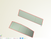
So I put this case in the attachment.
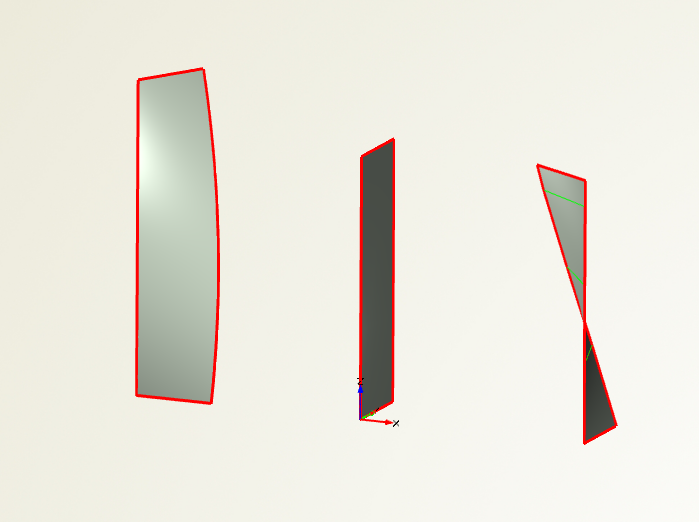
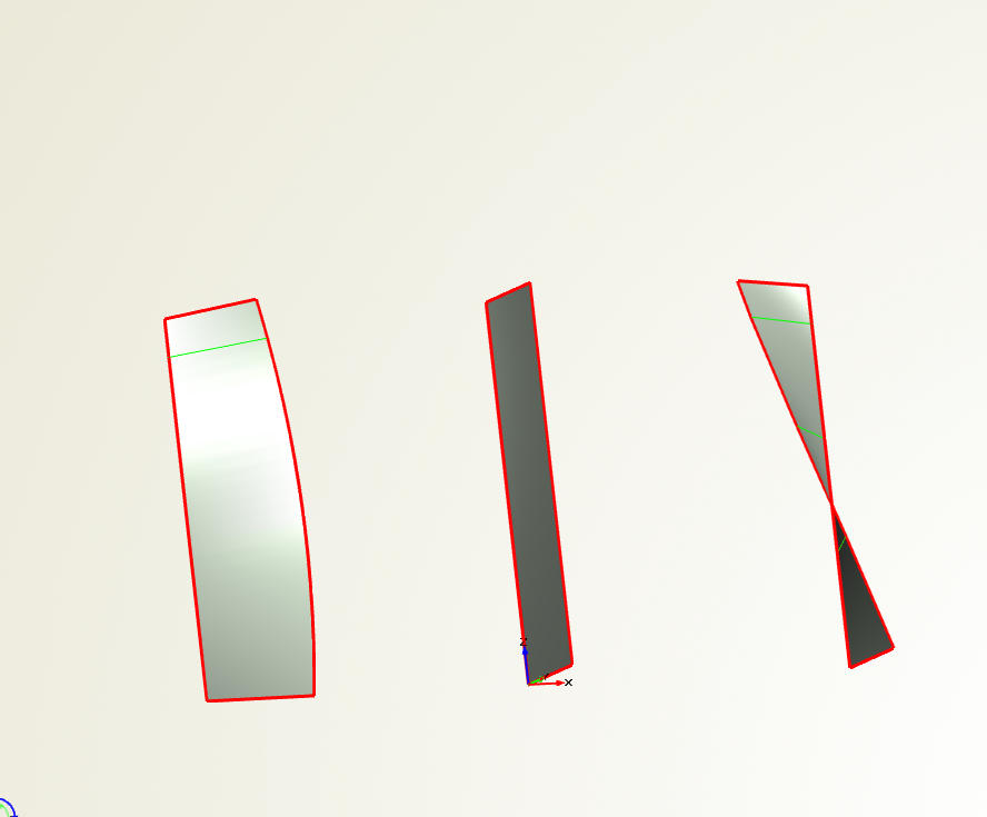
You can see here 2 rows of planes, the first one is twisted, the other one is just straight.They are equally long, but the twisted one has clear divisions, while the straight one doesn't have a division in the three last surfaces (see picture).
I also put the case in attachment
Cheers, and have a nice weekend
-
Hi Simon
Thanks for your reply.I'm afraid that the breps in the project that you uploaded don't have any sources (it gives an error). The second technique I didn't get, how do you protrude 2 times in a brep, since you want to make physically 2 different layers?
But I got the first technque.
So instead of creating one Brep and trying to protrude it all at once, I should just add the boolean operation "difference" to all the different breps. Since I got a list of all breps I could make it with the following code line://FreeSupportls is the list of the Layers, FreeEndBoltHoles is the list of the holes. foreach (fbrep Source in FreeSupportls) foreach (fbrep Difference in FreeEndBoltHoles) Source.addOperation(brepBoolean([Difference],"Difference",NULL,true,NULL,NULL)) endfor endfor
And it worked!
Thanks for your helpCheers
Bram -
Hi
Currently I'm modelling everything of my project in Caeses and I came to the point where I'm installing the bearings for my application. Since the bearings will have to be aligned correctly and fast I'm applying a Chockfast layer underneath the bearing which is supported by a aluminium plate.
The bearing housing is imported (source: www.skf.com) and already has some bolt holes, so I'm trying to get a hole in the Chockfast and the aluminium plate in order to see on the other side where my bolts will be.I had following challenges:
- How to find the bolt hole from the imported bearing housing
- How to make subsequent layers
- How to get a hole in all these layers
After some thinking I came up with the following strategy:
- Feature Definition BearingScaling: scales and transforms the imported bearing + housing to my desired scale (from mm to dm (don't ask me why ^_^ )) and combines them in one brep.
- Feature Definition BearingPositioningFrame: Locate the bolt holes by getting the locations the starting/ending points of some carefully picked edges on the BREP from the imported geometry. This way you get the general dimensions. This feature definition creates 2 points which are the centre points of the bolt holes.
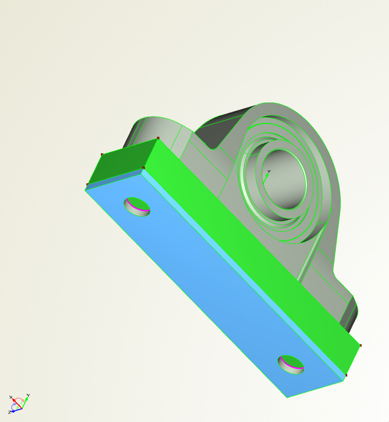
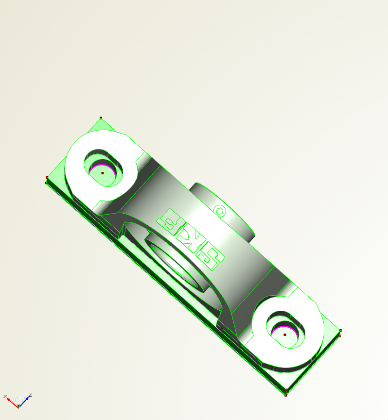
- Feature Definition support: Make 4 points on the outer sides of the bearing housing. Create a rectangular plane with these points. Create a Brep which extrudes this plane and closes it (so it's a beam). This is layer 1. Create again 4 points exactly like for layer 1, but you add the thickness, so they are positioned on the outer part of layer 1. Proceed with these points similar as to layer 1 (make plan, brep, extrude) this is layer 2. Add all these layers to an fobjectlist of Layers (so when an additional layer comes you just add it to this list). Then you make a brep of a circular axis (which will be the bolt hole) and you make a copy of it which you translate (I need 2 bolt holes) and you add it to an objectlist of Bolt holes. All of the above you put on not-visible (".isVisible(0)"). Then you make a new brep with as input the objectlist with the layers, you add a boolean operation "ExlusiveOr" with the object list of bolt holes and tadaaa, you should have your bolt holes.
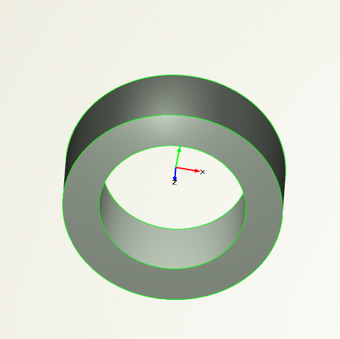
Up until the boolean operation everything went well. The input list for the layers does give the desired result, the list for the bolt holes makes the boolean operation fail. So I needed to repeat the boolean operation manually for each bolt hole or make loop which iterates through the bolt hole list in order to get the boolean operation to succeed. Besides this, there is still a plane in the end, in between the two layers, which isn't removed (see picture).
Note: I realize that in order to make the second layer I could use the plane of layer 1 with the commando: .getSurface(#numberHere), but I can't find out what the number is of the plane that I want. I could find it with trail and error, but than we don't have a generalized solution, so I rather opt to just make a new plane.
So my questions are:
- Is there a better/faster/easier strategy to get the desired result?
- How do I remove the plane which is blocking my bolts?
- How do I get the number of the surface I need to make Layer 2
Have a nice day
Bram

-
Dear
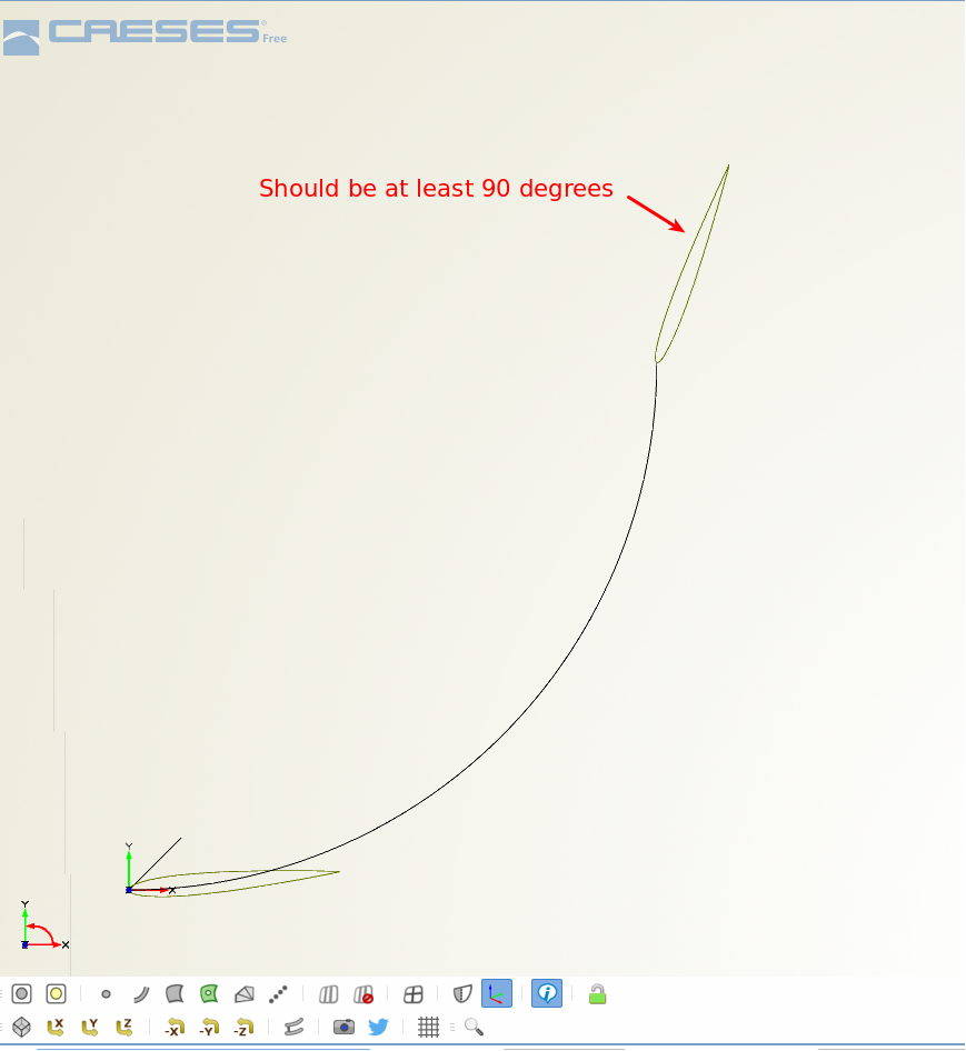
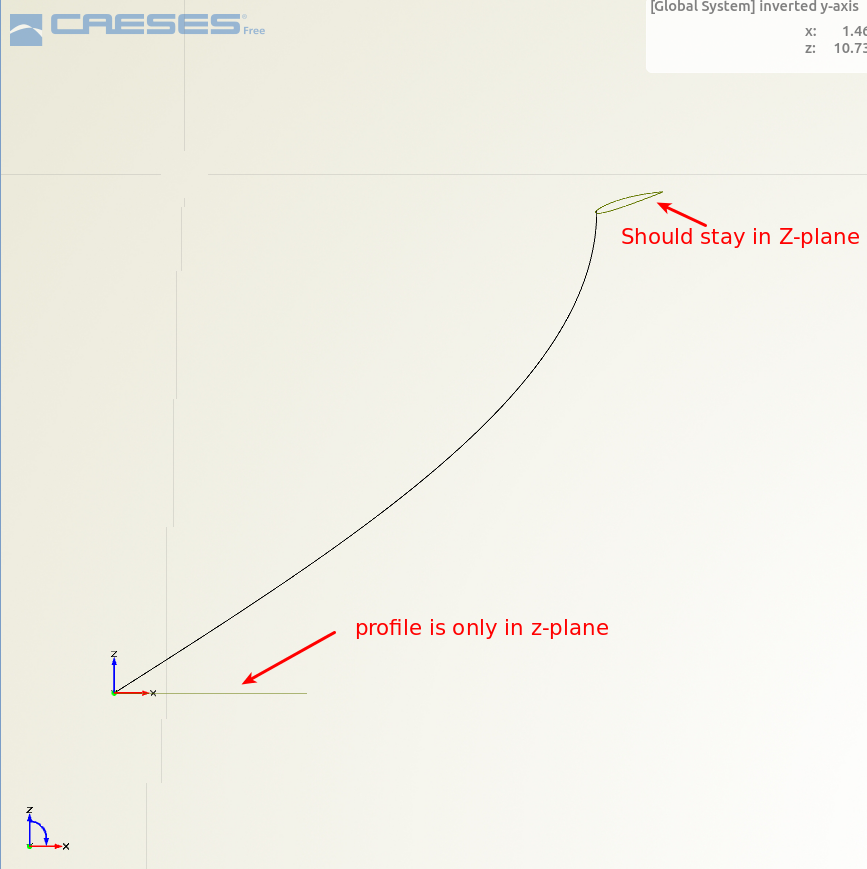
I'm currently trying to model a helical (Gorlov) turbine.
After creating a blade profile (in the Z-plane) using the Fnaca4ds function and using FsweepTransformation to sweep the profile along a helical path.
In this particular case the helical path covers only a quarter of a helix (so it goes for about 90 degrees). The blade profile therefor should also turn 90 degrees and remain in the Z plane.
For now this isn't what happens. I believe that the orientation of the 2D profile to the sweep-line is defined in respect to the line and not to the coordinate system of the blade profile. Therefor the blade profile twists and turns and doesn't stay in the Z-plane.
I've tried already to get around this by using an image to create a pressure and suction side of the profile. therefor you can define the "start" end "end" on the attack and trailing edge. Using these points in order to use metasurface with skinning and two rail functions, in order to keep these points on the rails didn't work, it gave some issue's with overlapping triangles.
So the question is: how can I make a blade profile follow a certain path and control the orientation of the blade profile.
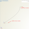
picture "selection_003" is the view in the z-plane, where the rotation of the profile isn't the desired 90 degrees.
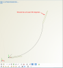
Picture "selection_004" shows that the profile twists a bit out of the z-plane
-
Hi Konrad
I believe I'm on the trail of the cause of this problem.
The file when I change the name of (or delete) libstdc++.so.6 (found in /home/bram/CAESES_4.0.3_Linux.x86_64/lib/Linux.x86_64), so it isn't found anymore, Caeses starts. I believe this has to do with a problem of accessing the application/x-sharedlib file, which should direct to the correct driver.But now it has some errors, but it starts.
initializing features ...

initializing configuration ...
	configuration - ok

updating geometry - ok
X Error: GLXBadContext 172
  Extension:    155 (Uknown extension)
  Minor opcode: 6 (Unknown request)
  Resource id:  0x3a00175
X Error: BadValue (integer parameter out of range for operation) 2
  Extension:    155 (Uknown extension)
  Minor opcode: 3 (Unknown request)
  Resource id:  0x0
X Error: GLXBadContext 172
  Extension:    155 (Uknown extension)
  Minor opcode: 5 (Unknown request)
  Resource id:  0x3a00175
X Error: 0 0
  Extension:    155 (Uknown extension)
  Minor opcode: 26 (Unknown request)
  Resource id:  0x0
QGLContext::makeCurrent(): Failed.
X Error: GLXBadContext 172
  Extension:    155 (Uknown extension)
  Minor opcode: 5 (Unknown request)
  Resource id:  0x3a00175
X Error: 0 0
  Extension:    155 (Uknown extension)
  Minor opcode: 26 (Unknown request)
  Resource id:  0x0
QGLContext::makeCurrent(): Failed.
X Error: GLXBadContext 172
  Extension:    155 (Uknown extension)
  Minor opcode: 4 (Unknown request)
  Resource id:  0x3a00175
and while closing:
QGLContext::makeCurrent(): Cannot make invalid context current.
QGLContext::makeCurrent(): Cannot make invalid context current.
QGLContext::makeCurrent(): Cannot make invalid context current.
QGLContext::makeCurrent(): Cannot make invalid context current.
QGLContext::makeCurrent(): Cannot make invalid context current.
QGLContext::makeCurrent(): Cannot make invalid context current.
QGLContext::makeCurrent(): Cannot make invalid context current.
QGLContext::makeCurrent(): Cannot make invalid context current.
QGLContext::makeCurrent(): Cannot make invalid context current.
QGLContext::makeCurrent(): Cannot make invalid context current.
QGLContext::makeCurrent(): Cannot make invalid context current.
QGLContext::makeCurrent(): Cannot make invalid context current.
QGLContext::makeCurrent(): Cannot make invalid context current.
QGLContext::makeCurrent(): Cannot make invalid context current.
QGLContext::makeCurrent(): Cannot make invalid context current.
QGLContext::makeCurrent(): Cannot make invalid context current.
I'll let you know when I find out how to solve these errors.
-
Hi Konrad
I've the same problem. I've the Ubuntu 14.04 and I get this error while initiating Caeses.
view typeslibGL error: unable to load driver: r600_dri.so
libGL error: driver pointer missing
libGL error: failed to load driver: r600
libGL error: unable to load driver: swrast_dri.so
libGL error: failed to load driver: swrast
X Error: BadValue (integer parameter out of range for operation) 2
I've already installed the driver as per: http://askubuntu.com/questions/588024/steam-install-error-on-14-04-ubuntu-64bit
sudo apt-get install libc6:i386
sudo apt-get install libgl1-mesa-glx-lts-trusty:i386
And it is on my machine. I've also copied the files (r600_dri.so and swrast_dri.so) from
/usr/lib/x86_64-linux-gnu/dri
to
/home/bram/CAESES_4.0.3_Linux.x86_64/lib/Linux.x86_64/missing_libs
but Caeses didn't start.
I've also tried copying to
/home/bram/CAESES_4.0.3_Linux.x86_64/lib/Linux.x86_64/
but still nothing.
Do you have any ideas?
Kind regards
Bram -
Karsten
Still doesn't work, but we're heading the good way. I didn't use the mintty.exe ( since it wasn't clear that I should use it). When I only put as argument ";/Allrun" it creates an output file (pin.dat). When I put the whole "-|stdouterroroutput.redirect ./Allrun", it says that it doesn't recognize the "-|" part.
Also what I've noticed is that when I open the mintty.exe it says: bash: uname: command not found [next line] your "" operating system is not supported.... bla bla bla. I don't know if this has anything to do with it, since I've already done some tutorials (directly) in OpenFOAM and than there wasn't a problem.
Regards
Bram
-
Karsten, Carsten
Thanks for the reply, I was abroad for my job and couldn't check it until today, so sorry for the late reply :).
It still doesnt work. I've tried the new Allrun file with both RunFunctions files (original and the one from higher up this page), but it didn't change anything. What is like the main change in this other RunFunctions file?
This is what is in the stdouterroroutput.redirect file:Moving C:/OpenFOAM/cygwin64/home/Bram/OpenFOAM/Design/connection with openfoam/Sduct with openfoam/manual_results/baseline/Runner01/input/0 to C:/OpenFOAM/cygwin64/home/Bram/OpenFOAM/Design/connection with openfoam/Sduct with openfoam/manual_results/baseline/Runner01//0
Moving C:/OpenFOAM/cygwin64/home/Bram/OpenFOAM/Design/connection with openfoam/Sduct with openfoam/manual_results/baseline/Runner01/input/Allrun to C:/OpenFOAM/cygwin64/home/Bram/OpenFOAM/Design/connection with openfoam/Sduct with openfoam/manual_results/baseline/Runner01//AllrunMoving C:/OpenFOAM/cygwin64/home/Bram/OpenFOAM/Design/connection with openfoam/Sduct with openfoam/manual_results/baseline/Runner01/input/constant to C:/OpenFOAM/cygwin64/home/Bram/OpenFOAM/Design/connection with openfoam/Sduct with openfoam/manual_results/baseline/Runner01//constantMoving C:/OpenFOAM/cygwin64/home/Bram/OpenFOAM/Design/connection with openfoam/Sduct with openfoam/manual_results/baseline/Runner01/input/system to C:/OpenFOAM/cygwin64/home/Bram/OpenFOAM/Design/connection with openfoam/Sduct with openfoam/manual_results/baseline/Runner01//systemThis is what the Allrun file now looks like:#!/bin/bash #!/bin/sh if [ -z $WM_PROJECT_DIR ] ; then echo "\n\nERROR: Your openFOAM setup is not correct. No openFoamDotFile loaded." OFFILE=C:/OpenFOAM/cygwin64/opt/OpenFOAM/OpenFOAM-2.3.x/etc/bashrc if [ -f $OFFILE ] ; then . $OFFILE else echo "\n\nERROR: no openFOAM dot file found.\n\nTry to modify the Allrun.sh in SoftwareConnector" exit 1 fi fi #wmUNSET #wmUNSET #source C:/OpenFOAM/cygwin64/opt/OpenFOAM/OpenFOAM-2.3.x/etc/bashrc.win . C:/OpenFOAM/cygwin64/opt/OpenFOAM/OpenFOAM-2.3.x/bin/tools/RunFunctions blockMesh.exe -dict constant/polyMesh/blockMeshDict 2>&1 | /usr/bin/tee.exe $BLOCK_LOG snappyHexMesh.exe -overwrite 2>&1 | /usr/bin/tee.exe $LOG #checkMesh.exe simpleFoam.exe 2>&1 | /usr/bin/tee.exe $LOG /usr/bin/touch.exe case.foam patchAverage.exe p -latestTime sduct_lightpink > pin.dat
Sincerely
Bram
-
Hi
I'm currently also using OpenFOAM 2.3.x for Windows. When I try the connector as per tutorial (Sduct with OpenFOAM), it doesn't work. I believe this is because of the coding syntax, so I tried your Allrun.sh-file and i replaced the RunFunctions-file in the OpenFOAM\cygwin64\opt\OpenFOAM\OpenFOAM-2.3.x\bin\tools. But still the same error.Error message:
*** INFO Runner : finished results [design: baseline]
*** INFO Runner : Preparing process ... [design: baseline]
*** INFO Runner : Writing command files ... [design: baseline]
*** INFO Runner : Finished preparation - running external process ... [design: baseline]
*** INFO Multi Body STL Export : processing [exporting 1 object(s)]
*** INFO Runner : running external process [Allrun.sh in design baseline]
*** INFO Runner : Results are pending
*** INFO LocalResourceManager : External process start failure [starting process C:/OpenFOAM/cygwin64/home/Bram/OpenFOAM/Design/connection with openfoam/Sduct with openfoam/manual_results/baseline/Runner//Allrun.sh failed: Process failed to start: ]
*** INFO Runner : finished results [design: baseline]
Would you happen to know what to do about this?
Sincerely
Bram

Syntax error in new version 4.1.1
in General Modeling
Posted · Report reply
Hi Stefan
Thanks for your quick reply.
Yes it is in a function. Alright, I adapted it and it works, Thanks!
Bram