


Mr. BUGRA UGUR YAZICI
-
Content Count
13 -
Joined
-
Last visited
Posts posted by Mr. BUGRA UGUR YAZICI
-
-
It works very well for me with the .bat workaround. :)
Vielen Dank!
-
Hi again,
I realized something about FProcess issue. When I pass arguments in the feature definition, output file has no newlines and args aren't written on the file.
The output file that is created within the FProcess and passing arguments as it is written with the above instructions:
VCB :8.4946106VCB :8.8417073VCB :9.2119383VCB :8.4946106
The output file that is created with same arguments within a .bat file:
VCB :8.4946106
VCB :8.8417073
VCB :9.2119383
VCB :8.4946106
['C:\\Users\\bugur\\Desktop\\CAESES_Thesis\\Msc_Thesis_Setup\\GM_table.py', 'deneme']
Revised feature:
//string exe("c:/Python27/python")

//string os(resolveEnv("$OS"))

//if (os.contains("Windows"))
  //exe.append(".exe")
//endif

//process myTool(exe)

//myTool.setArguments(["C:\Users\bugur\Desktop\CAESES_Thesis\Msc_Thesis_Setup\GM_table.py", "deneme"])
//myTool.run()

string exe("../../pit.bat")
process myTool(exe)
myTool.run()
Inside .bat file :
c:\python27\python.exe C:\Users\bugur\Desktop\CAESES_Thesis\Msc_Thesis_Setup\GM_table.py deneme %*
I just wonder why there is a difference between executing .bat file and .py file in the feature definition.
Thank you very much for your time and understanding.
-
Dear Joerg,
Thank you very much for your answer.
Just to speed up the process for newbies like me :
string exe("c:/Python27/python") string os(resolveEnv("$OS")) if (os.contains("Windows")) exe.append(".exe") endif process myTool(exe) myTool.setArguments(["<pathofpythonscript>", "arg1"]) myTool.run() -
Hi,
I would like to know whether it is possible to execute python script directly within a feature definition.
I don't want to use software connector option because python script should be executed in an if-else statement. If the condition doesn't meet the requirements, python script will not be executed.
Thank you very much in advance.
-
Hey Carlo,
Thank you for atan() perspective!
I can now get what i want :)
-
Hey,
I wonder if there is any possible way to assign dimension angle as double in FDimensionAngle feature?
I need to use dimension angle value in another function. But as far as i could see there is no such function defined in FDimensionAngle class.
Best Regards.
-
If the colors are visible/used in another tools pends on the tool itself.
With the color stl export the colors are written in the corresponding label in the stl file. Therefore if the tool accepts these labels they should be visible. I don't know how Cradle treats these color labels. Maybe they do not support them. Which leads to a no colors.
The multibody stl is a bit different. The color is used to separate the boundaries and the bodies name will be the color name. (Each color will be an individual body inside the stl)
The multibody stl does not support any color labeling therefore the colors won't be visible in Cradle or any other tool.
The two solids:
You would like to have a box for air(upper part) and one for water ( lower part) ?
And should the air and water boundaries also be visual on the inner box?
Take a look at the scope karsten. Not sure if this is what you would like to achieve but maybe it helps.
Cheers,
Karsten
Hey Karsten,
Thank you very much for your quick response. It has solved my problems.
There is a problem with Cradle as you mentioned before, because it is visible with Numeca.
By the way, your solution to solid part is lifesaver for me. Cheers!
-
Hi Simon,
I am using last version of commercial CAESES.
Which software did you use to import this stl file? Because i've imported it both to SC/Cradle Tetra and Hypermesh and colors are absolutely invisible.
Besides, could you help me with the second part of my question about solid intersections/free surface?
-
Hey,
I've regenerated "Domain Box" feature of CAESES with my own requirements. Whenever i export the geometry i created with this new feature, exported stl geometry doesn't have colours on its surfaces. I couldn't understand why.
You can find feature in attachment.
Besides, i really wonder whether it is possible to select/modify a surface of solid or trimesh. I need to create two closed volume for SC/Cradle CFD software for multiphase ship analysis so that i need to cut my boolean geometry with a plane to create the free surface.
Best Regards.
-
Thank you very much for your fast reply. It solved my problem very well.
-
Hi,
I am working on a ship optimization project.
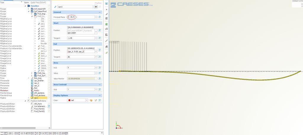
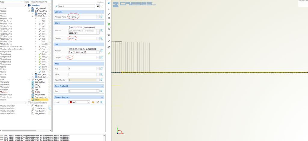
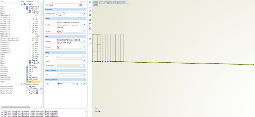
I have some problems with Fspline curves. Due to their fairness, i want to use Fsplines. But whenever i try anything instead of using XY coordinate system, i get a single line instead of Fspline whose start and end tangent don't work properly.
Below, there are 3 images. The first and the second one show "how to become a line instead of Fspline" :)
Latter one shows the exact Fspline characteristics.
Could you further explain me which type of optimized curve i should use instead of Fsplines? I would be appreciated if you take into account that I don't want many control points in my design.
Thanks.


Same Variants in Genetic Algorithms
in Ideas and Suggestions
Posted · Report reply
Hello,
I am not sure if it has recently changed in CAESES, but I have a suggestion to speed up optimization process.
Same variants from the previous populations are created and analysed again and again. Of course, it is the nature of the genetic algorithms and nothing to do with CAESES. However, it would be very nice if CAESES searchs for all designs one by one to see whether current variant is identical with one of the designs created before. If this is the case, just copying the results, analysis files and all the other documents from same variant's folder to the current one should be enough. Exhaustive search is much more faster than performing CFD/FEM analysis.
Stay healty and safe.