


Erik Bergmann
-
Content Count
8 -
Joined
-
Last visited
Posts posted by Erik Bergmann
-
-
Hi Etienne,
Thank you for the file. The output says that CAESES is using software rendering instead of any graphics hardware.
We have two problems now:
1. If the graphics drivers installed correctly, CAESES should not be running in software rendering mode.
2. Even when using software rendering, the surfaces should not be red.So I have some additional questions:
1. Which graphics card are you using?
2. Are you maybe running CAESES using a remote desktop connection?
3. Could you try clicking on the pencil icon in the lower left of the 3D-Window and then select "Environment/Warehouse with lights" and see if this changes anything or produces error messages in the console?Thank you,
Erik
-
Hi Etienne,
I would like to add two questions:
1. Does the CAESES-console display any errors after you start CAESES?
2. Could you run the command getGLInfo() in the CAESES-console and send us the output?
Best regards,
Erik
-
Hi,
You can try to permute the coordinates of the normal in line 52 of the file.
The original line reads:
vec3 n = normalize(normal);
Try
vec3 n = normalize(normal).yzx;
or
vec3 n = normalize(normal).zyx;
instead.
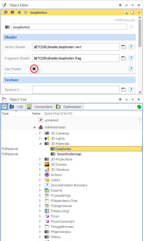
After you have edited the file, make sure that it is reloaded in CAESES by selecting the material and clicking twice on the "Use Shader" checkbox (see image).
Regards,
Erik
-
Hello Oliver,
It is possible to export a series of screenshots which can then be joined afterwards in a video editing program to produce a video file (there are a couple of free and easy to use programs that can make a video from a series of images).
To create a series of screenshots you will need an FTimer, which is a simple object that contains a command list that is executed repeatedly at certain settable intervals.
The most basic setup would be the following:
Create a parameter and name it "screenshotCount". In the paramter's object editor set "value" to "0" and activate "Design Variable".
Create an FTimer ("Visualization->Timer") and insert the following as "commands":
[screenshotCount += 1, IF(screenshotCount < 101, [skyView.screenshot("c:/tmp/shot" + asString(screenshotCount, 5) + ".png")])]
(if necessary change the word "skyView" to the name of your skybox, but it should be "skyView" by default.)
Now, if you click on the timer it should write 100 screenshots to "c:/tmp/" (this may take a while).
I will attach a project file that contains three features that encapsulate this basic principle and also add some other stuff.
The most simple feature is called "screenshotsOnly". It executes the above setup and adds two attributes to let you specify the duration of the "video" and the number of screenshots that will be taken per second of the video.
It contains a button "Take Screenshots" which will start the timer and write screenshots to the specified destination.
The second feature ("camOnly") does the same but adds the ability to move the camera along a specified path. This path can be set using the attribute "Position Curve" of the feature.
The attribute "Viewpoint Curve" allows you to set a second curve to specify the camera's viewing direction during the animation.
If you deactivate the toggle "Use Curve for Viewpoint", a fixed position for the camera to look at can be specified instead.
The button "Toggle Timer" starts the movement of the camera along the path. The camera can be reset to the start of the curve by pressing the "Reset" button.
If you want to take screenshots you need to activate "Screenshots->Take Screenshots" before you press "Toggle Timer".
The third feature ("camAndShip") sets up the timer to also move the ship. You can specify how far the ship should travel during the animation period.
If you test the features and the buttons do not seem to work, make sure the attribute "Sky Window" of the feature contains the name
of the sky view loaded with the project in quotation marks (it should be "skyView" by default but might be "skyView01" or something similar if you already have a sky view in your user config).
If it still does not work, right-click the feature and select "Run" from the context menu - after that the buttons should work.
Another very important thing I just noticed: due to a bug the sky view in the project might not be loaded correctly. To prevent that from happening, just open the 3DView before loading the project.
I hope this helps, if you have further questions please don't hesitate to ask.
Erik
-
These two commands are leftovers from an earlier version and are not functional anymore. Unfortunately they have not been removed yet.
What you are looking for is setting a transformation for the camera.
There are two ways to go about that:
The first way is to specify a coordinate system using a point of origin and a second point the z-axis of the system should point at.
This coordinate system can then be used as transformation for the camera.point camOrigin(0,0,0) point camViewPoint(0,0,1) coordinateSystem camSystem() camSystem.setOrigin(camOrigin) camSystem.setAlignment(camOrigin+camViewPoint) 3DCam.setTransformation(camSystem.getInverseMatrix4())
The origin used in the coordinate system will then be the position of the camera and the alignment of the system will be the point the camera is facing.
By making the alignment relative to the origin ("camOrigin + camViewpoint"), camViewPoint effectively behaves like a vector specifying the viewing direction of the camera.
So changing camViewPoint to [1,1,1] will rotate the camera by 45 degrees around the X- and Y-axes for example.
If you change camOrigin to [0,0,1] for example, the camera will move one unit to the right, effectively moving the scene one unit to the left.
If you want to also rotate the camera around the viewing direction, you can use the following:parameter rollAngle(0) camSystem.setAngle(rollAngle)
Changing the parameter rollAngle will then roll the camera around the viewing direction.
The second way lets you specify the viewing direction using Euler angles by utilizing a transformationchain.
rotation camRotationX(parameter angleX(0),0)
rotation camRotationY(parameter angleY(0),1)
rotation camRotationZ(parameter angleZ(0),2)

translation camTranslation(0,0,0)
transformationchain camTransformation([camRotationX, camRotationY, camRotationZ, camTranslation])

coordinateSystem camSystem()
camSystem.setTransformation(camTransformation)

3DCam.setTransformation(camSystem.getInverseMatrix4())
With this setup you can change the rotations around the axes by changing the angle parameters.
The translation controls the position of the camera. This could also be parametrized of course.
Please note that by default an orthographic projection is used. This means that the camera does not have a perceivable distance to the scene,
so moving the camera along the viewing direction does not change the size of the displayed objects as would be the case for a perspective projection.
Also, objects will even be displayed if they are technically behind the camera, which might be confusing when changing the position of the camera.
In order to change the size of the displayed objects you will need to use the command .setZoomLevel() of the camera.
Surfaces are always displayed colored red
in Miscellaneous
Posted · Report reply
Thanks for the additional info. The default and plain color environment don't have maps, because they are procedurally generated which seems to fail on your machine in software rendering mode. We will have to look into this issue and hopefully resolve it in the next release. But I think you can work for now?