


Mr. Iorga Stefan
-
Content Count
22 -
Joined
-
Last visited
Posts posted by Mr. Iorga Stefan
-
-
Hi Stefan,
in case of a propeller blade I don't know why to use trimmed surfaces. A subsurface from a brep will not work. So the only case, where I can think of problems is the blade analysis, but here trimmed surface can be avoided pretty easy I guess.
best regards
Carsten
Hi Carsten,
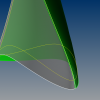
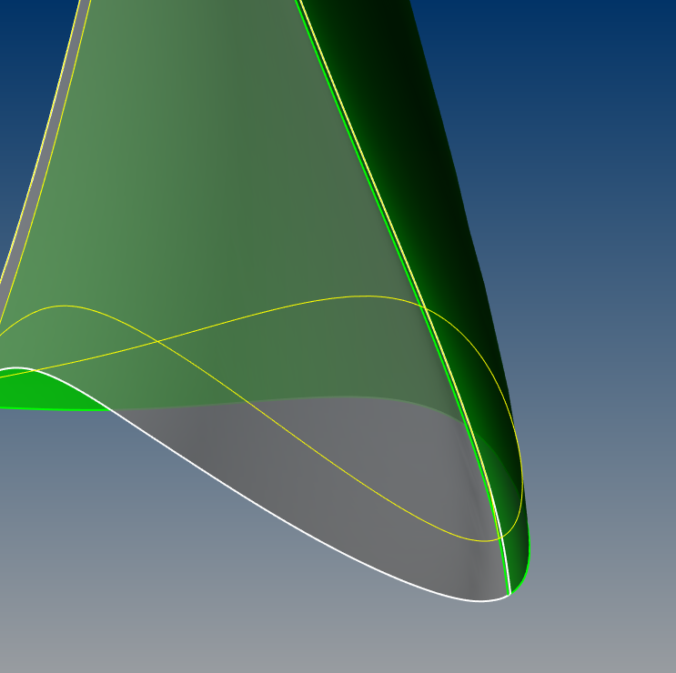
Look at the green colored blade face how it's over-lapping with the grey colored one.
The yellow curve is the edge of the blades if they were untrimmed.
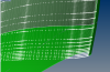
In the second image the control points of the nurbs surface is activated.
I was thinking to import in CAESES the boundary curves as well as two nurbs surfaces and trim them back. Otherwise, the BladeAnalysis feature is giving erroneous results.
Sure, I can rebuild the surfaces, but it's taking far too long.
Best regards,
Stefan
PS: This is off-topic already, can you modify accordingly the title?
Later edit:
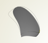
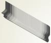
The only way I suppose this will work, is by importing as BrepsParts and Extract Surfaces and Boundary Curves, however, the results are not as expected:
-
Hi Stefan,
now I don't get your point. You can use any brep to convert to stl, no matte if it is trimmed or not. I am not seeing your problem.
Carsten
I was thinking of blade analysis feature that requires as an input NURBS/BSpline surfaces. Suppose you import a trimmed blade face.
But, this is another topic.
Thank you
-
Thank you very much Stefan for your link.
Have you done any Shipflow CFD analysis for JBC with Energy Saving Device (ESD)?
Regards,
Nabila Naz
Hello,
Just the bare hull, XPAN only, to observe the wave pattern and then for VOF computation, in another unstructured grid CFD software. The smallest error i could get is around 4.3%.
Best regards,
Stefan
-
Hello,
I remember I've found the IGES files here: http://www.t2015.nmri.go.jp/jbc_gc.html
Be aware that the origin is somewhere amidships. As far as I know there's no rudder.
Best regards,
Stefan
-
 1
1
-
-
Hello,
I think Mr. hamid reza asked how to create several identical 2D views with the same scale and position of the entities displayed, similar with copy view/frame of Tecplot.
Am I right?
Best Regards,
Stefan
-
Hello,
Finally found it for those interested: http://www.t2015.nmri.go.jp/Instructions_KCS/instruction_KCS.html
Also, if someone is in need of the KCS propeller 3D geometry I can provide it (send me a private message - I also received it, is not modeled by me, I have no credit)
Best Regards,
Stefan
-
Hello,
I was wondering if someone is willing to share as much as possible infos about the 7.2 meters KCS model.
The websites were these informations were available are down for a long time I suppose.
I'm working on a validation case and I don't have any resistance test results curve to compare with. I'm only finding Ct values, but w/ water density and precise wetted surface I can't get RT exactly.
Thank you very much,
Stefan
-
Sorry, wanted to post a thing, but found the solution.
This reply should be erased.
Thank you
Edited
-
Well, I don't know well but I think you Need to check first if the Offset Group was created correctly.......... and try to enlarge grid size from vcoa to a larger.
And please Keep in mind that Flowtech People can help you much better :).
Daehwan
Eventually, I will do that, you're right.
Thank you for your assistance.
Best regards,
Stefan
-
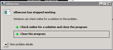
Thanks for the reply - I've got this (is a new error at least :-)
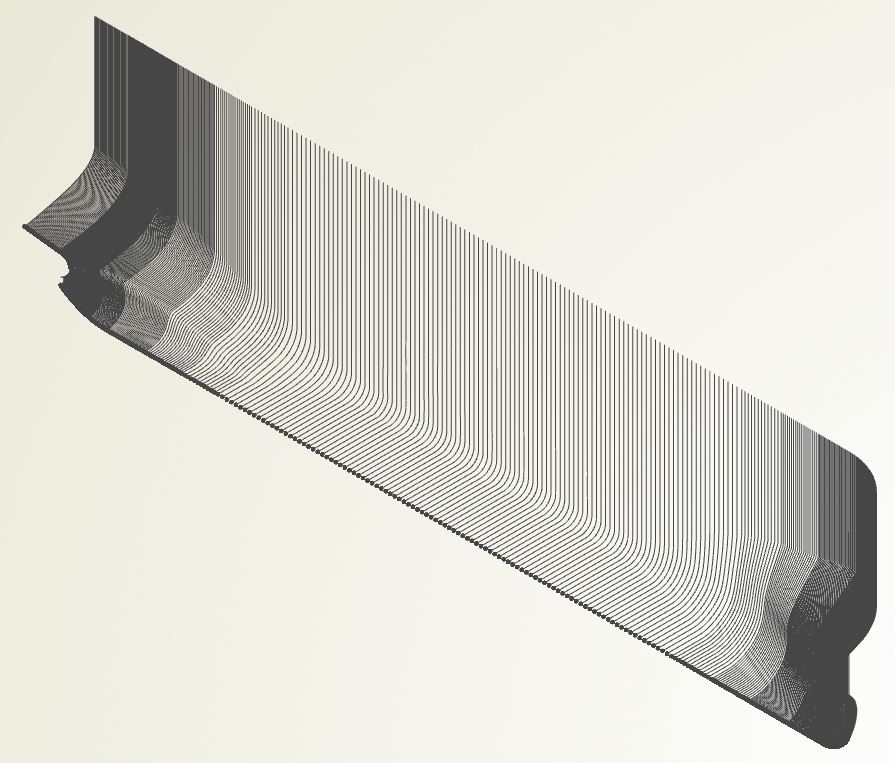
-Running XOFFGEN
Translating xchap_test3.igs -> xchap_test3.stlHull type: monoCreating Groups:- main ||||||||||||||||||||||||||||||||||||||||||||||||||||||||||||||||||||||||||||||||||||||||||||||- bulb |||||||||||||||||||||||||||||||||- aft |||||||||||||||||||||||||- boss |||||||||||||- bow |||||||||||||||||Offset file written to: C:\Users\Administrator\Desktop\XCHAP_test_3\off_xchap_test3done.SHIPFLOW 6.0.00 ( Revision: 10369 )Educational licenseLicensed under the SHIPFLOW EDUCATIONAL LICENSE AGREEMENT--- To be used only in academic education ----Running XBOUND-Running XGRID*This seems to be a full scale case andthe default grid dimentions for XGRID are for modelscale. Please consider adding 50% extra cells inthe normal direction (ZETAMAX).**ERROR in ant.f. # of points in spline to largeforrtl: severe (157): Program Exception - access violationImage PC Routine Line Sourcexflow.exe 000000013FEF74A0 Unknown Unknown Unknown3FDB9A3790C9D1A7 Unknown Unknown Unknown3FDB9BF717BE562F Unknown Unknown Unknown....3FE9915DE8D81EE0 Unknown Unknown Unknown3FE9BA885C9F8481 Unknown Unknown Unknown3FE9E3B2D066EA21 Unknown Unknown Unknown3FEA0CDD442E4FC2 Unknown UnknownStack trace buffer overflow; further frames not shown. Regardless (ZETAMAX) - it say there are too many points on the stations?Here is the command file generated by ShipFlow after all that above:xflotitl(titl="tk_100.7_XCHAP")prog(all)hull(mono,vof,h1gr="main",fbgr="bulb",abgr="boss",ogrp="aft")offs(xaxd=-1,ysig=1,xori=100.7,zori=6.5,lpp=100.7,file="../off_xchap_test3")vshi(rn=[6.365814030131828e08],fn=[0.237373050372614])flui(dens=1025,visc=1.18e-006,grav=9.806649999999999)prto(strl)opti(on)control(exepath="C:\FLOWTECH\SHIPFLOW6.0.00-x86_64\bin\..\\bin/",runid="C:\Users\Administrator\Desktop\XCHAP_test_3\tk7000_RUN_DIR",rundir="C:\Users\Administrator\Desktop\XCHAP_test_3\tk7000_RUN_DIR",casedir="C:\Users\Administrator\Desktop\XCHAP_test_3")endxgrisize(vcoa,glob)offs(h1gr="main",fbgr="bow",abgr="boss",ogrp="aft")endxchapara(nthr=4,npro=1)cont(star,tecp,adi,maxi=8000)vof(rhor=0.01)endThank you,Stefan
 -
Dear friends,
Before jumping mailing Flowtech's support, I might get better chances to get quicker answers here.
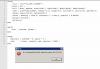
My first 3 trials using XCHAP, without VOF, converged eventually, although not being enable to post-process the results using Tecplot (SHIPFLOWPOSTPROC = TECPLOT is declared in the Windows system environment variables). The command file and the error looks like
Using XOFFGEN I generated the offset file, up to the deckline, removed bow group, but extracted the stem profile from it and included the station into the bulb group. Is there any way I can declare all the groups in the command file without altering XOFFGEN generated file? Or maybe the instruction offs ( iges = "name.igs" ...) without declaring groups at all?
I was instructed to use an IGES hull and "VOF" instruction in the command file (in order to capture the free surface), and it's deck extruded with construction height and then generate with XOFFGEN the offset file
 and I get negative volume cells, and some other times, errors regarding "not enough memory"
To summarize, can someone provide an example of a command file using an IGES file and VOF altogether?
Later edit: And what is that error in Tecplot?
Thank you very much!
Best regards,
Stefan
PS: We are using ShipFlow 6.xx release, on a 12 GB memory Windows machine
-
Hello,
I was very busy these days, sorry for not replying sooner.
I am afraid I can't share the model since it's for a commercial work.
Meanwhile, I've exported the model in rhino, I'm working the surfaces in the aft part, fore it's done.
I think it's simpler this way, I can modify the PMB easily, even in Caeses I have a lot of utilities to transform the hull.
Afterwards, ShipFlow knows how to manage IGES surfaces to generate a very nice offset file, much better than I would manually.
My only question remains if ShipFlow's offset generator will work on IGES trimmed surfaces, since I had unfortunate results in a FEA software importing trimmed IGES surfaces - it "seen" the trim.
Thank you very much!
Later edit:
If you'd like, I can generate a IGES 3D lines plan for KCS, for example, and share it.
-
Good morning,
I have a ship lines plan originated from Tribon (Lines).
I can export all the curves to Rhino in IGES format and then, the hard way, divide the stations into 60 - 80 points, then export to Excel and sort each station by Z values, resulting the offset file to be used with ShipFlow.
This is how at school we work. It's a tremendous job to sort over a hundred stations in Excel.
I wander if there is an easier way to do this, given the IGES file with sections, waterlines, buttocks, boundary curves.
Thank you very much!
-
Dear Stefan,
In general, all our parametric bulbous bow designs should be able to be shaped like delta, nabla or oval type bulbs. It is just a matter of finding the right values for all functions. For a nabla bulb one should reduce lower fullness of the bulb profile, increase the upper fullness a bit and also increase the keel start angle (deadrise). Also one should raise the maximum beam function (increase the start z value). I think when applying this changes to the bulbous bow setup it should look like a nabla type bulb.
The modeling of the connection of bulbous bow and hull is sometimes a bottle neck and is different from hull to hull. In one of my cases I found it to be
sufficient to use the surface-to-surface-fillet feature (you can find this feature e.g. in the RoPax-sample > derivativeJointCurve feature) between the bulbous bow and the lower hull. With the similar feature which creates a fillet between surface and curve (you can find this feature in the Features tab > Hull Design > Smooth joint to stem) I created the small triangle-like surface above the bulbous bow (so to say the start of the stem). From the position where the stem has its minimum x-value I used the second mentioned feature again. So I got rid of the coons patch completely. As both features create the same 4-Points-BSpline-Curve it is possible to model this part watertight, as long as these fillets are short in x-length.
1) The hull surface goes almost to the end of the waterline (e.g. waterline:end:x - 1)
2) Surface to surface fillet, based on the 4-Points-BSpline
3) Smooth joint to stem feature
4)Again the Smooth joint to stem feature (as usual)
Why did I create the surfaces 3) and 4) and not only one surface for the stem part? -- Because this makes the small triangle-like part above the bulbous bow a bit more flexibel with regard to the surface resolution.
I hope this helps. I will create a small sample for that in the next days.
Best regards
Matthias
Thanks for sharing this out - and a small sample will be excellent, not only to me, but to all newbies in Caeses, wondering about this matter.
Sorry for writing so little, though, when I'll be ready with a such a model, I'll gladly share it here.
Thank you very much Matthias !
Kind regards,
Stefan
-
Hello,
I've started to learn Caeses for a while - hull modeling techniques are quite understandable, feature definition, etc - though, all the models provided includes delta bulbs connected to the hull with a coons-patch.
The trends in shipbuilding, as you all know, involve a nabla bulbous bow, due to seakeeping, mostly slamming (hammer blow - in romanian), etc.
I've taken a break working in Caeses, since I've been quite occupied with various projects, school, some work, etc., and I don't yet have the time to dig into Caeses more than I did last summer/autumn.
Anyway, I wanted to ask you some guidelines, maybe a forebody hull model you want to share, with a nabla bulb, faired nicely, without a coons-patch - let's say similar to KCS.
Thank you very much,
Stefan
-
Hello,
Sorry for the long delay, I was away from a computer these days.
I want to thank you for the replies, though, I can't find a specific method yet. Hmm, I will ask my teachers, and post it back here, maybe someone else is interested about this topic.
Kind regards,
Stefan
-
Hello,
I mentioned in the previous post that this is not Caeses related, sorry for misunderstanding.
Let's say we have a given hull, open it in Rhino, project a line from side and get the full load draft waterline shape seen from top.
Is there a specific method, empirical or other way, to evaluate for that given hull it's entrance angle?
I mean, how do I choose the tangent point along the WL curve?
Thank you,
Stefan
-
Hello,
I forgot to tell you that this topic is unrelated to Caeses. Is just a general matter, because when you chose a random tangent point along the waterline you get different entrance angles.
Shortly, I'd like to know if it's a standard procedure to measure the entrance angle.
Thank you very much!
-
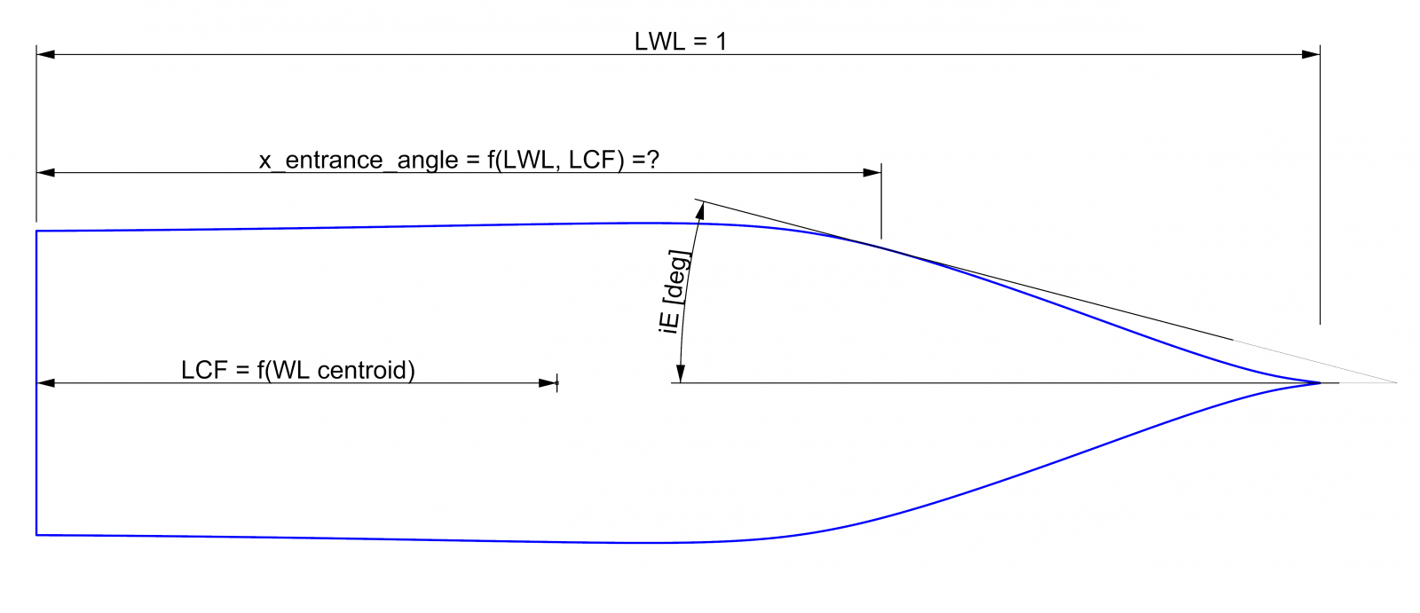
Hello,
I was wondering if there's a connection between LCF, area of WL, etc., in order to find out a proper distance from the transom (let's say) to the tangent point, from which the half entrance angle iE is measured.
Sadly, I can't find any reference for this matter.
See the attached image.
Thank very much,
Stefan

-
Hey,
Jörg, Mattia, thank you very, very much for your help.
I'll start with these, and hopefully, I will share with you my work soon enough.
Many thanks, Stefan. :)
-
Hello everybody,
I've just graduated Naval Architecture Faculty and I'm eager to study furthermore hull form optimization and CFD.
I just have skills in modeling double curvature surfaces using Rhino and Grasshopper and, I suppose, a good sense evaluating empirically a hull form definition.
My goal would be to switch from Rhino to Caeses - to generate a full parametric hull geometry.
There are many examples in Caeses's tutorials, though, none regarding ”how to create a parametric hull design, step by step”.
Silly it may sound, but can you give me some directions?
Thank you very much!


Trimesh from imported trimmed IGES surfaces
in General Modeling
Posted · Report reply
Mr Carsten,
What do you meant by saying that trimmed surfaces could be fairly easy to avoid?
Thank you!