


Mr. Jan Land
-
Content Count
8 -
Joined
-
Last visited
Posts posted by Mr. Jan Land
-
-
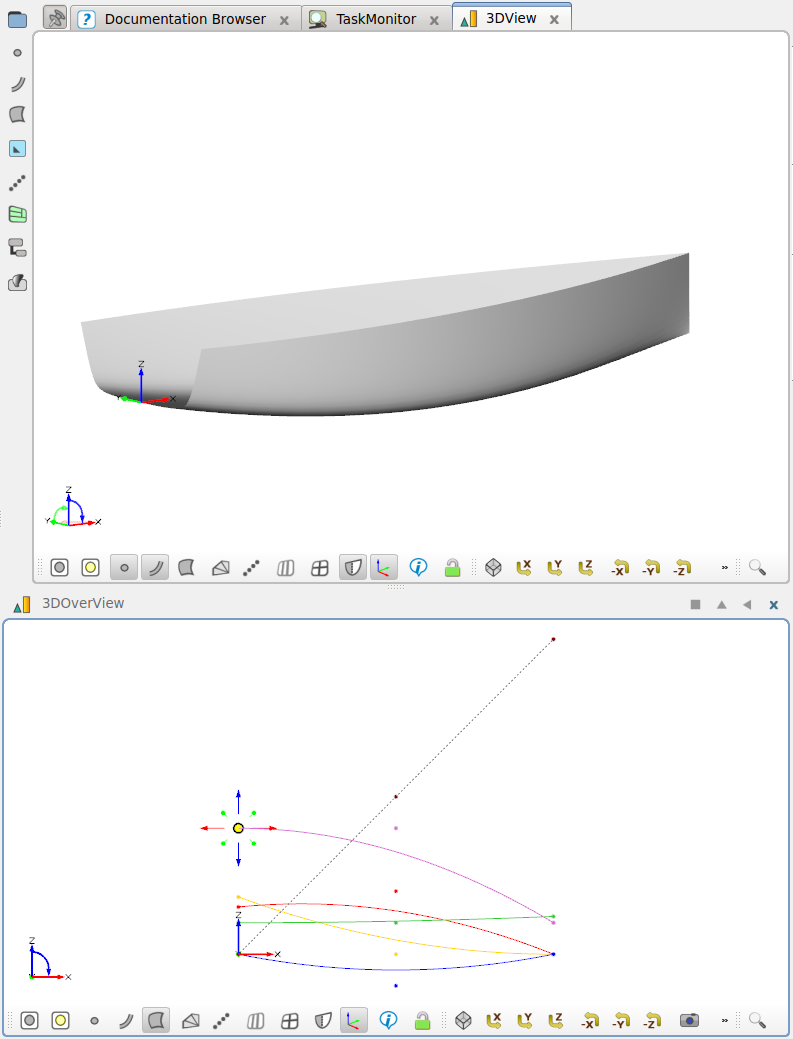
Hi all,
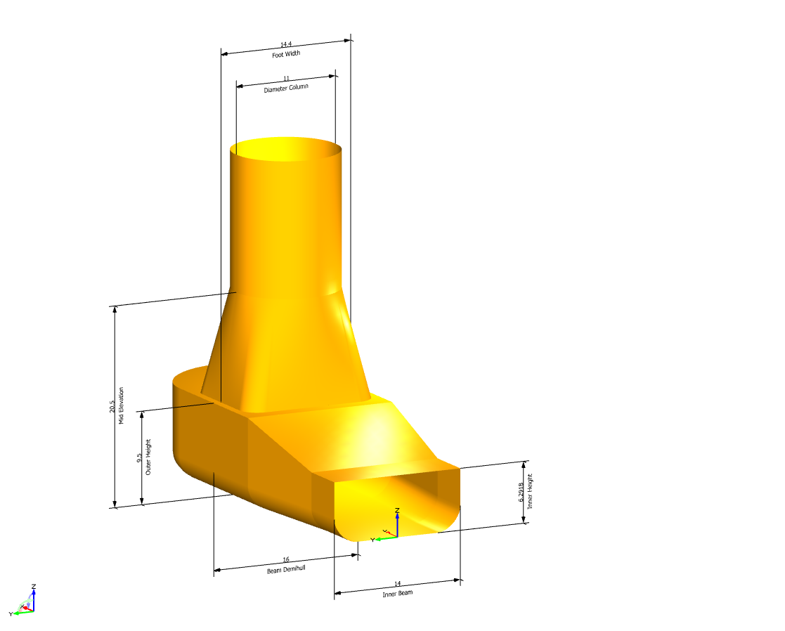
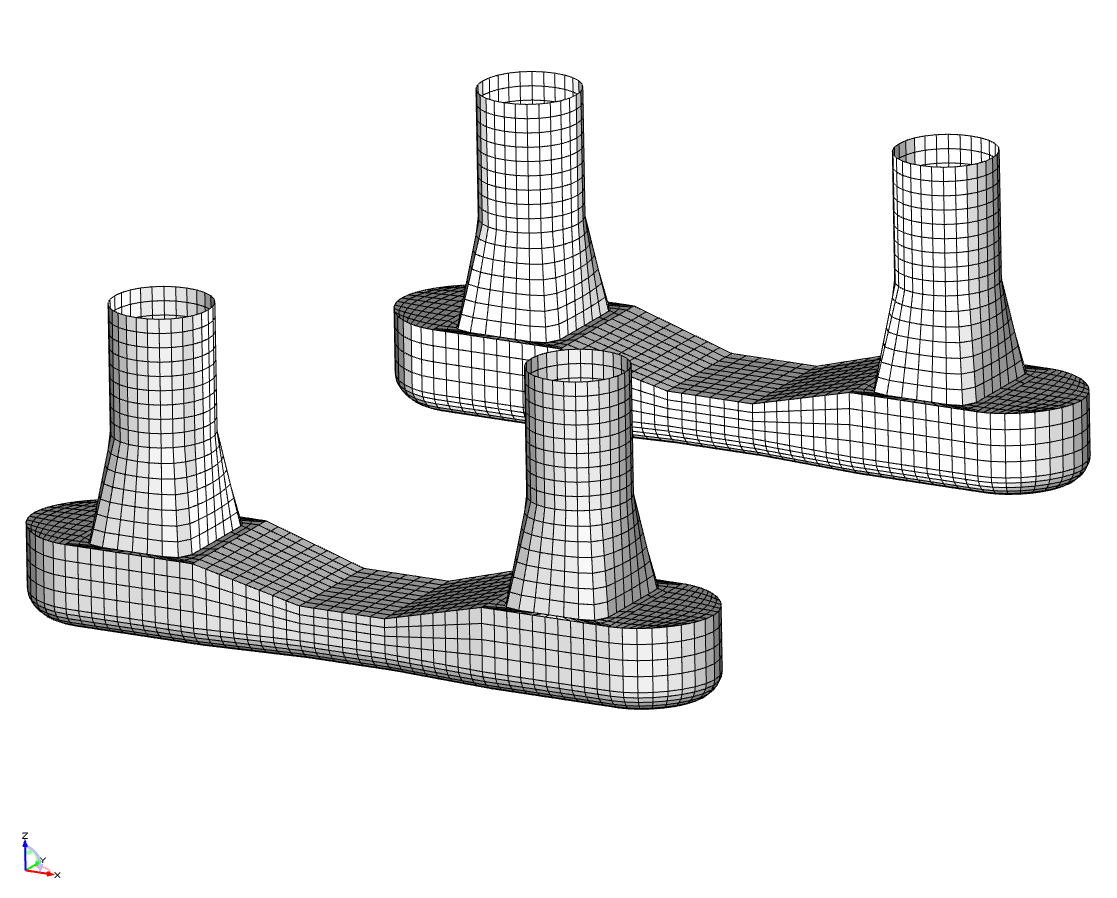
here is a parametric model of a semi-submersible created with CAESES.
I modeled only one quarter and then used two symmetry planes and GL Images to visualize the entire semi-sub. The dimensions can easily be controlled using the parameters and design variables to be found in 'baseline -> semiSubmersible -> parameters'.
There are a few special features in this project:
1) Note that when you change parameter values, e.g. "diameterCol", not only the diameter of the columns will change accordingly, but it will also affect the waist part of the pontoons. That is because there is a built-in constraint in order to keep the displacement fixed by adjusting the design variable "innerHeight". This internal, very simple optimization, can be found in the "Optimization" Tab in your Object Tree.
You can set the target displacement in the scope 'baseline -> semiSubmersible -> hydro'.
2) In order to use Sesam HydroD as a simulation tool, all the surfaces have also been used to create panel meshes. Check out 'baseline -> semiSubmersible -> meshes'.
3) There is a feature called 'ExportToSesam', which exports the meshes in the Sesam-characteristic ".FEM" format.
The project also includes the setup for software connections to Sesam HydroD and PostResp as you can see in the according Software Connectors. Of course the according license is required to run the simulation. The parameter 'maxRelMotion' will then hold the value of the maximum relative motion between the free surface and the platform deck in a given sea-state and can be used as an objective for optimization.
I am currently looking into possible applications for CAESES in offshore design and this is a first attempt. So let me know what you think, I'm looking forward to your feedback :-) Which other parameters do you think I should include?
Cheers,
Jan

-
 1
1
-
-
Hi,
For those of you who are interested in F1 racing, I created a simplified model of a rear wing.
In the project you have a bunch of parameters for global dimensions, as well as additional parameters controlling the local shape of main wing and flap, to be found in their respective scopes.
The design variable 'DRS_Angle' opens (~40° in the current configuration) and closes (0°) the drag reduction system (DRS). In the 'Optimization' tab in your object tree, you will also find a Design Lab. Create a new design and use the slider to try different settings for the DRS.
If you like the model, you can alter the parameters in order to adjust the wing to the current FIA rules and regulations:
http://www.formula1.com/inside_f1/rules_and_regulations/technical_regulations/
Cheers,
Jan
-
Hi Jurgen,
if I am not mistaken, the DELFTship free edition offers an export in STL format. CAESES can deal with that, so maybe that would be an easy way for you to transfer your geometry.
However, if you have a bit of spare time, it is definitely worth checking out a few CAESES tutorials on hull design. There is one on yacht hull design, too, which might be interesting for you. When built within CAESES, your designs will be fully parametric and ready for automatic shape variation.
Have fun with the software,
Jan
-
Hi Toni,
doubleclick your result value file in the Software Connector. You can then use the input field "Subfolder" to solve your problem, see the screenshot.
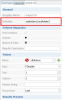
Cheers,
Jan
-
When working with Meta Surfaces a good way to keep things well organized is using two 3DWindows at the same time (e.g. one as a central widget, the other one as a docked widget below). Using the filter options (points, curves, surfaces and name filter at the bottom of each 3DWindow) you can display only the surface in one window and just the distributional functions in the other. This way you can alter the functions conveniently while observing the immediate effect your changes have on the Meta Surface.
-
1
-


Modeling of an intake port
in General Modeling
Posted · Report reply
Hi all,
Lately I've noticed that some of you, especially in automotive engineering, are interested in designing parametric intake ports, so here is one.
For better comprehension I will explain the main steps I undertook. Modeling the pipe (See tutorial and/or sample "Sweep Surface") and the valve itself (simple surfaces of revolution) shouldn't pose much of a problem after completing a few basic tutorials in CAESES. The difficult part is to model the intersection area where the valve pierces the pipe geometry.
Therefore I cut out an oval hole around the valve pin (see scope "02_domain_modeling"). In order to obtain a robust geometry, the remaining part of the trimmed surface has been split again into three subsurfaces (also to be found in the "02_domain_modeling" scope).
The hole has then been filled with a meta surface that connects tangentially constant to the surrounding pipe and to an additional support surface perpendicular to the valve pin (01_valve|02_misc|support_surf). The meta surface has been created in circumferential direction around the (half) valve pin, see Screenshots.
In the scope "03_functions" you can control the local shape of the meta surface. The blending function has influence on the connection to the support surface (1 = tangentially constant connection, 0 = perpendicular connection); speed_valve and speed_intake allow to manipulate the influence of the connecting surfaces on the meta surface. Use the mirror function in your 3D view to visualize the other half of the intake port, too.
Try playing around with a few parameters that can be found in their according scopes. For more detailed insight into the meta surface creation check out the feature definition "contour_def" which holds the curve description that is used for the meta surface.
the parameter "01_valve|03_motion|dz_norm" can be varied between 0 and 1 in order to close and open the valve respectively. "max_dz" in the same scope defines the maximum gap for an open valve. The .gif file should give you a few ideas how this fully parametric model can be varied, but you will probably have your own.
Looking forward to questions or feedback, let me know if you think this sort of geometry could help you improve your intake port designs.
Cheers,
Jan
20140523_simple_intakePort.fdb