


Gustaf Magnander
-
Content Count
16 -
Joined
-
Last visited
Posts posted by Gustaf Magnander
-
-
Hi,
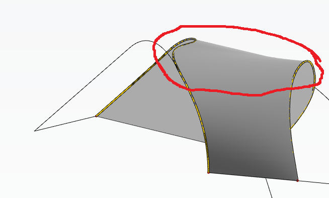
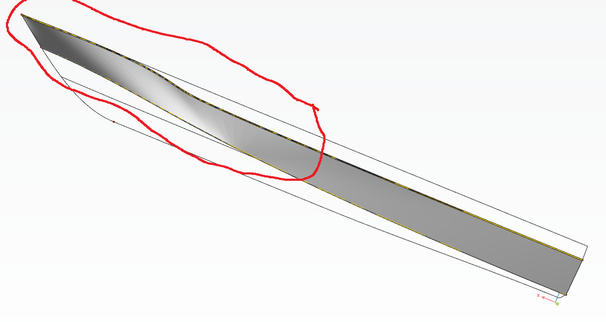
I'm modeling a ship hull and have generated a ruled surface between two generic curves (see the attached figures). However as you can see the surface doesn't look good slightly forward of LOA/2 and forward to the stem. The surface also bends inward, creating a curved surface and I'm wondering how I can fix these issues. I want the surface to be completely flat between the two generic curves and thought that a ruled surface should work, but I do not really know if a ruled surface is the best choice and if it can be controlled like I want to. If anyone can explain how I can control the surface and make it completely flat that would be great.
Thanks,
Best regards,
Gustaf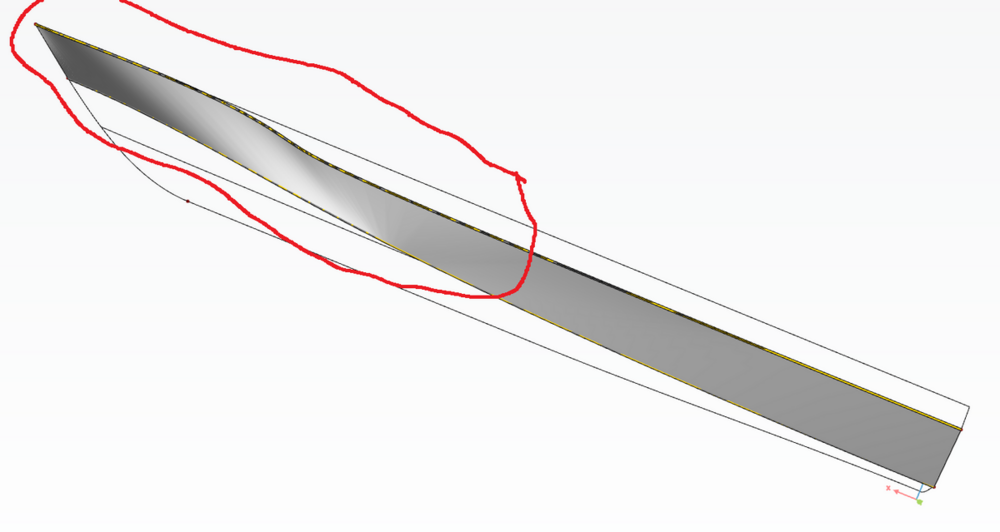
-
1 hour ago, Mr. Heinrich von Zadow said:Hi Gustaf (sorry for misspelling your name repeatedly!),
with .getmax(2,true) you can return the max value along the z-axis of a curve (the "true" will return the parameter position of that max value, instead of the value itself). This parameter can now be used again, to acces the position of the curve at that parameter with .getPos()
This should be what you need -- see attached project again for your specific example.
Hi Heinrich,
No worries!
Thank you, yes, I wanted to have the parameter position corresponding to the max z value. I will have a look in the project you fixed. Thanks again!//Gustaf
-
12 minutes ago, Gustaf Magnander said:Yea, it was, 🙂
Thank you Heinrich!actually Heinrich,
The x-value of the maxZ point was set as a discrete value. I want to automaticly retrieve this x-value based on the maxZ point, which change position if I vary the shape of the "knuckleRaiseCurve" Thus, if I vary the shape of the "knuckleRaiseCurve" in the xz-plane the point maxZ automatically get the max z-value, but I want to automatically also retreive the correspoinding x-value, when maxZ position changes. -
48 minutes ago, Mr. Heinrich von Zadow said:Hi Gustav,
well, that's the x-value 😉
See attached project...
Cheers,
HeinrichYea, it was, 🙂
Thank you Heinrich! -
6 minutes ago, Mr. Heinrich von Zadow said:Hi Gustav,
in your case you would have to us p2:z as elevation for the fv command:
point p1(curve.fv(2,p2:z))let me know if this explains it -- otherwise feel free to attach your particular example and I'll quickly modify it.
Cheers,
HeinrichHi Heinrich,
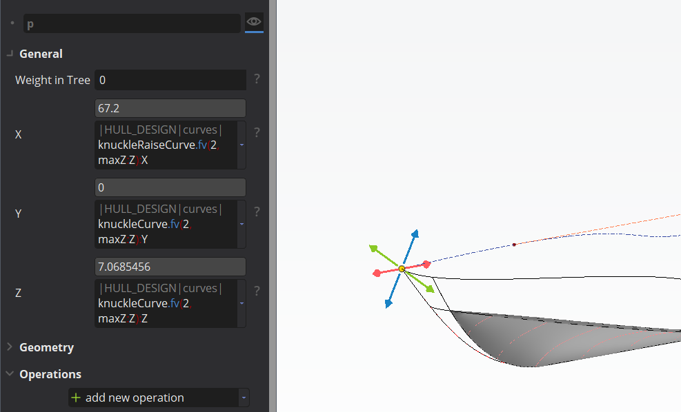
I actually use :z to get the z-value, see attached screenshot.
-
1 minute ago, Gustaf Magnander said:Hi again Heinrich,
I tested what you suggested and the points were created, but the position was wrong. I attach an image so it becomes easier to explain what I want to do.
The point I have marked "1" is the point which has the z-value I want to use. The red cross marks the approximate position on the curve where I want the new point to be. The point in the bow which I have marked with "2" is where the point actually is positioned after creating the point with: point p(curve.fv(2,zVal)).
I also tested the command: point p(curve.ft(2, zVal)) but then the point was positioned really far aft (not visible on the screenshot).
I hope this helps to describe my problem.
Thanks again!
//Gustaf
I could also say that the b-spline in the center works as a control curve and controls the outer generic curve in the z-direction. The point on the b-spline which is marked with "1" thus also has the correct x-value. I control the generic outer curve in the xy-plane with a multisegmented curve (not visible in the screenshot).
-
Hi again Heinrich,
I tested what you suggested and the points were created, but the position was wrong. I attach an image so it becomes easier to explain what I want to do.
The point I have marked "1" is the point which has the z-value I want to use. The red cross marks the approximate position on the curve where I want the new point to be. The point in the bow which I have marked with "2" is where the point actually is positioned after creating the point with: point p(curve.fv(2,zVal)).
I also tested the command: point p(curve.ft(2, zVal)) but then the point was positioned really far aft (not visible on the screenshot).
I hope this helps to describe my problem.
Thanks again!
//Gustaf -
49 minutes ago, Mr. Heinrich von Zadow said:Hi Gustav,
you could create a point through the console with:
point p(curve.fv(2,zVal))Instead of "curve" you'll have to choose your particular curve and zVal would be your z value. "2" corresponds to the z-axis (0=x, 1=y, 2=z).
Thank you Heinrich, I will try this and also the ft alternative that you suggested
//Gustaf
-
Dear forum members,
Is there an easy way to find the normalized value, that represent a certain real z-value, that I can use for the "Tp-value" when using the point type "position on curve"?
Thanks,
//Gustaf -
59 minutes ago, Mr. Claus Abt said:Hey Gustaf, is there any reason why you stick to CAESES 4?
Hi Claus,
At my work we have both versions, but since I'm relatively new to use CAESES and my "mentor" has not used C5 yet, we decided that I should use C4 while I'm learning our templates for ship hulls. I have started to use C5, though, and my plan is to only use C5 very soon.
Kind regards,
Gustaf -
Hi again Mr. Claus Abt,
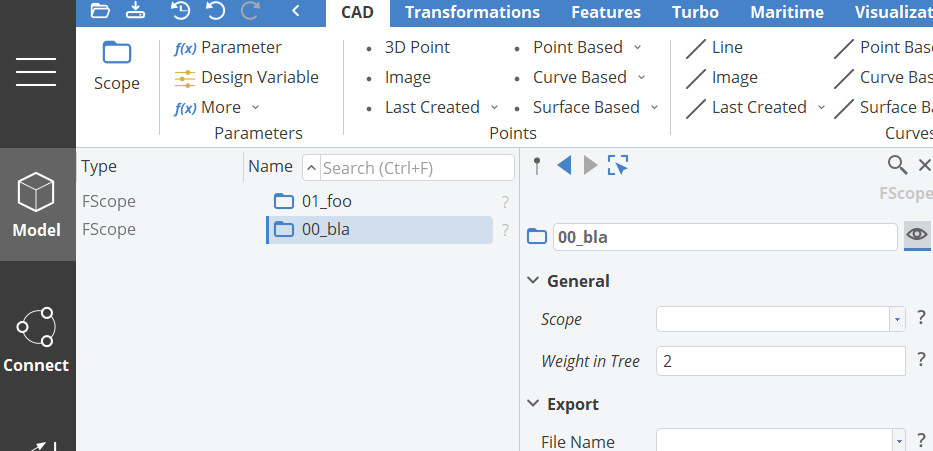
I cannot find the "Weight in Tree" setting in CAESES 4, but I find it in CAESES 5, so I guess this is a new feature only available in C5!?
Kind regards,Gustaf
-
2 minutes ago, Mr. Claus Abt said:Hi Gustaf,
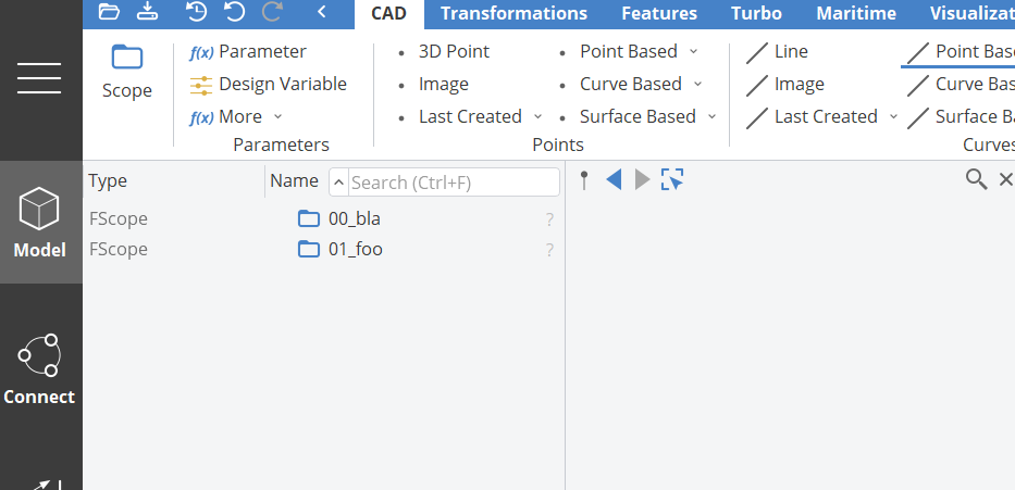
currently you can only use appropriate names to sort the scopes alphabetically or, use weights for the items, see attachments.
Hi Mr. Claus Abt,
Thank you for the reply and description of how to organize the contents.
Kind regards,
Gustaf -
Dear CAESES users,
I would like to organize the object tree, but the usual "drag & drop" feature does not work and I cannot find another way, like an "edit-mode", that allows me to move, for example, FScopes and FParameters up and down in the object tree and thereby organize the contents. If there is a way to organize the object tree, I would be very grateful if someone could enlighten me.
Thanks,
Kind regards,Gustaf Magnander
-
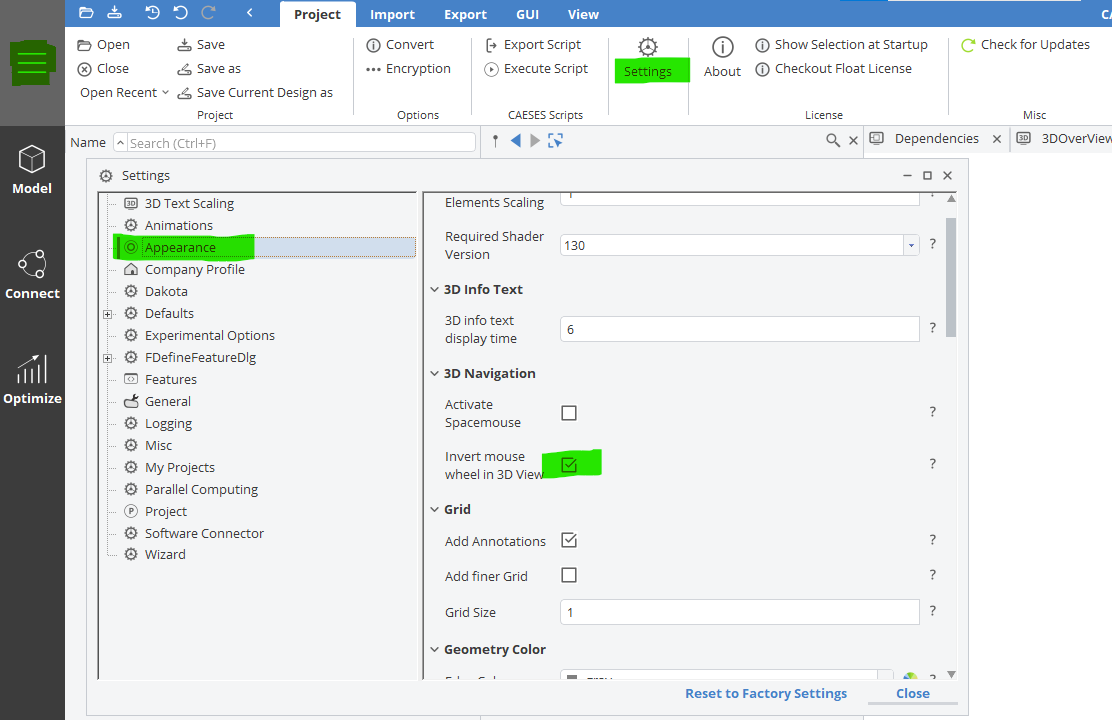
17 hours ago, Mr. Heinrich von Zadow said:Hi Gustaf,
you can adjust the zoom direction in menu > setting > appearance:

Best regards
HeinrichHi Heinrich,
Thank you very much!
Best regards,
Gustaf -
Hi,
I'm a relatively new user of CAESES and would like to tweak my mouse settings. However I cannot find any setting for this, therefore this topic/question.In the registry editor (on windows) I have manually adjusted so that when I scroll on a web page, the contents is coupled to the scroll wheel and not the vertical slider, which is default. In Linux environment this tweak is called "natural scrolling". In both Rhino 3D and Autodesk Inventor, two examples of software I frequently use, I can tweak the mouse settings, so that when I'm working in a 3D environment, the model is moving towards when I scroll towards me, and vice versa. I would like to be able to tweak also this in CAESES, but I cannot find the setting for it. Now, a 3D model is moving in the opposite direction to my scroll wheel direction and that is not very pleasant.
Does anyone know if this is possible to achieve in some way?
Thanks!

how to manipulate a ruled surface?
in General Modeling
Posted · Report reply
Hi Claus,
Thank you for your reply!
I already created a ticket concerning this this hull, however not about the issues connected to the the ruled surface, and have got help from Fabian Thies who looks at the ship in general terms, so I can ask him more about the ruled surface tomorrow if I'm not satisfied after playing with the parameterization.
Kind regards,
Gustaf