


Gabriel Caldeira Vicente
-
Content Count
8 -
Joined
-
Last visited
Posts posted by Gabriel Caldeira Vicente
-
-
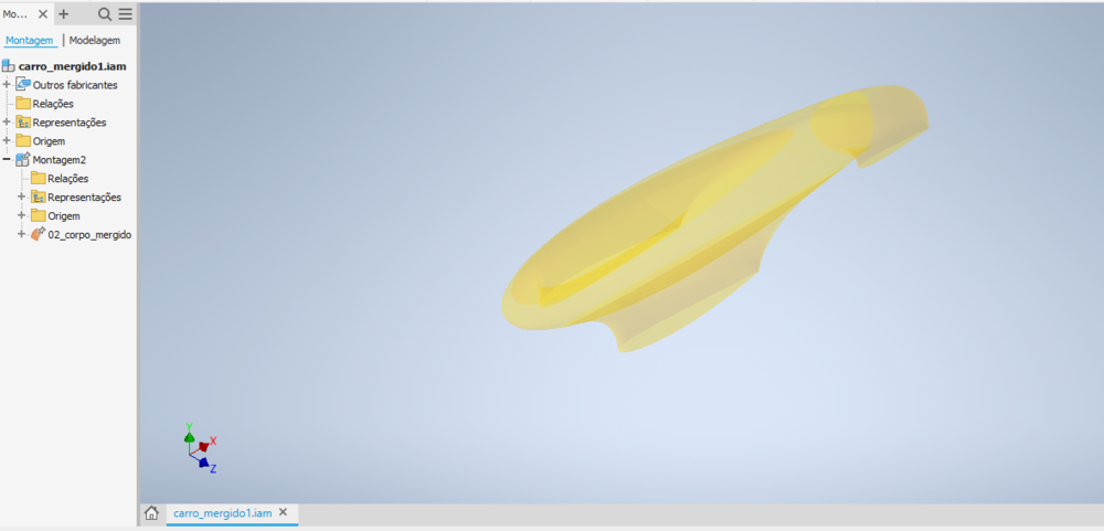
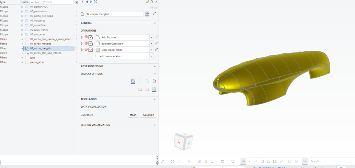
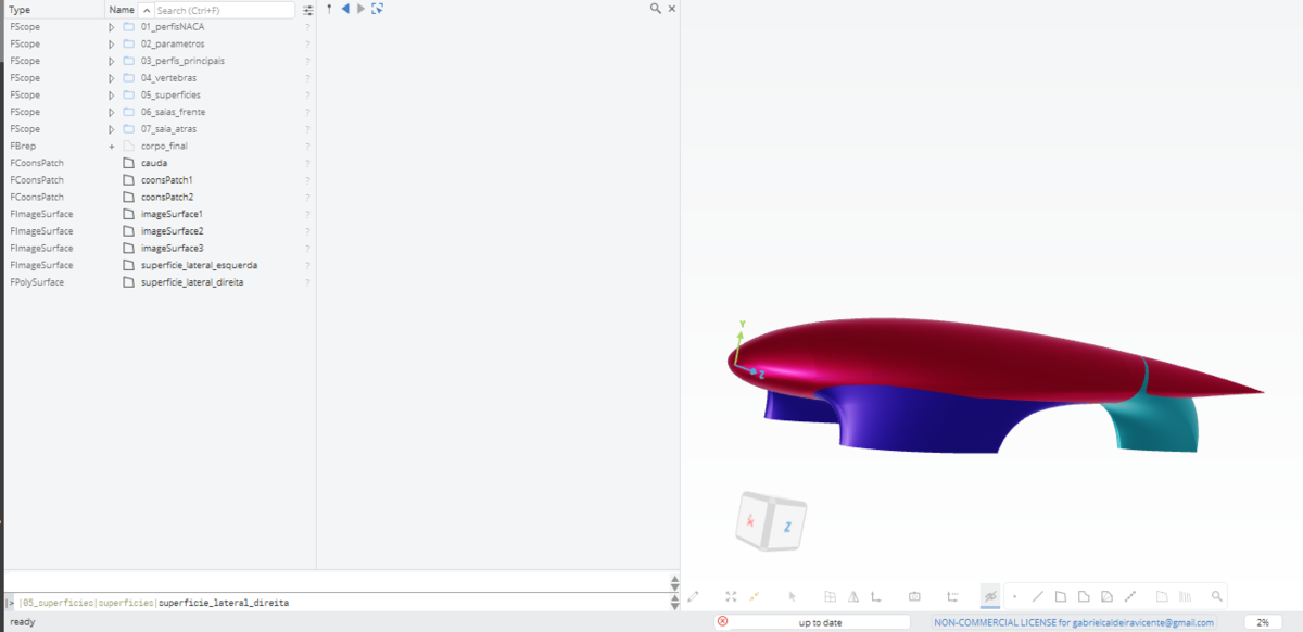
The following image is the model i created in CAESES.

The point is: i need to export this design as a rigid body, but when i try to export just the final BRep (the one selected on the tree in the image above) i finish having just the surfaces i created.
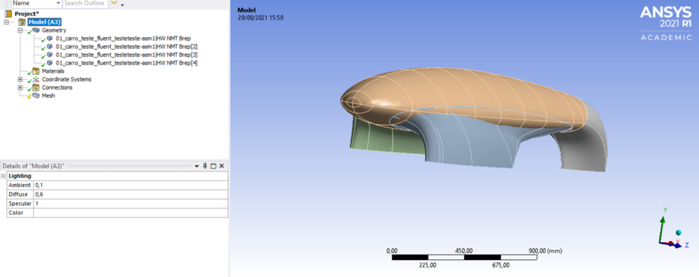
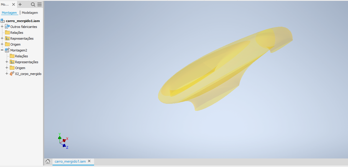
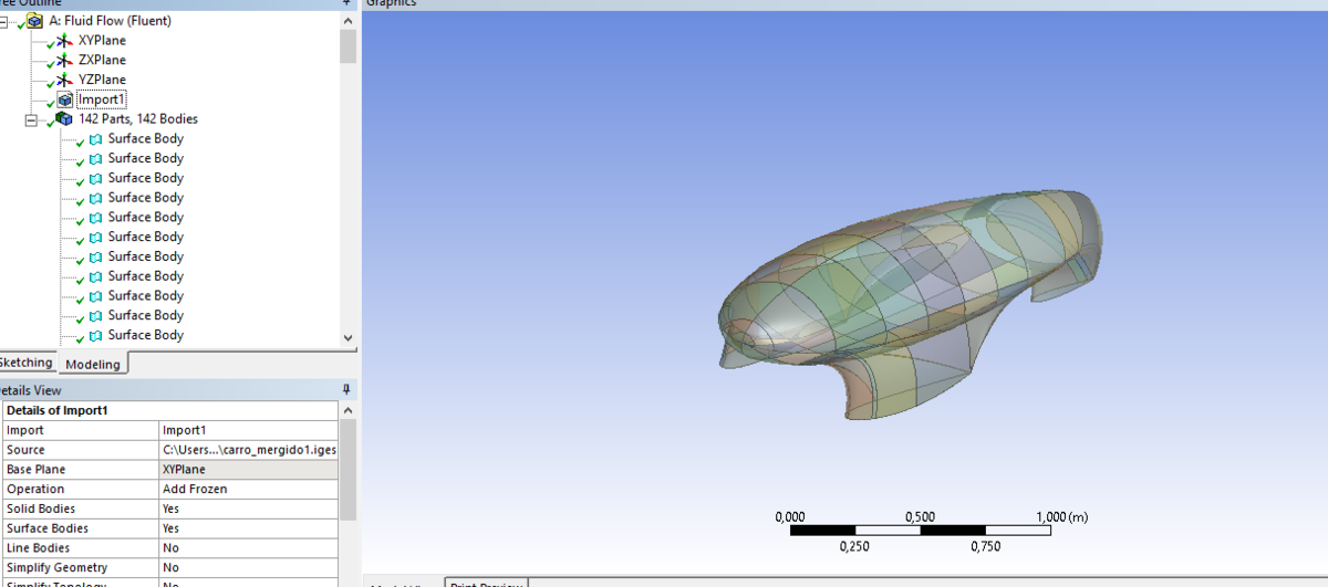
The following images are the result that i have when i open the exported file on the softwares Inventor and Ansys (this one on the Design Modeler plug-in of Fluent) respectively.

Could you guys help me to create a rigid body which has this contours? Maybe i am not exporting the file correctly, maybe there is a solution in CAESES or Ansys, but i have no idea.
-
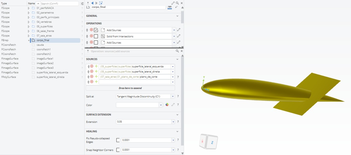
Firstly i created half of the model and then duplicated each part of it with an opposite Image Surface.
After that, i used the feature BRep to create the final design, so i added the right and left sides and a plane as my sources to cut in the second step the "tail" of the model.

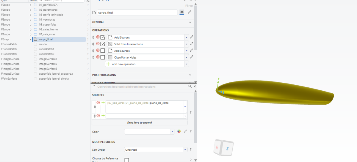
Now i used the operation "Solid from Intersections" to cut the "tail" and got the front part of the body.

Finally, i added as source the other parts of the model (the legs) and used the operation "Close Planar Holes" to close the bottom of the "legs".
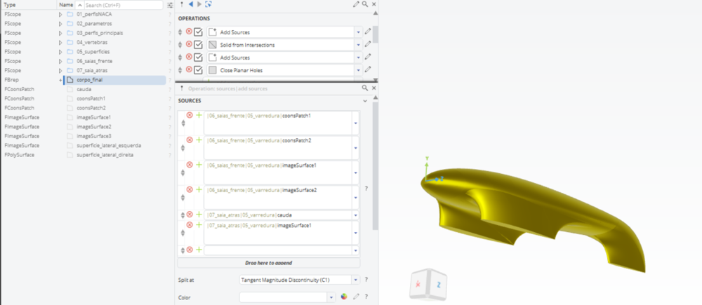
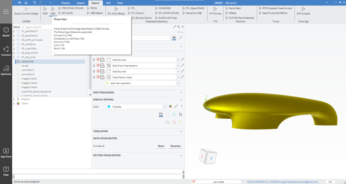
After finished, the model i added a color ("fullbody") for it, selected the BRep and tried to export the model an IGES extension like the image attached bellow.

Note: I created all the surfaces using the feature Coons Patch.
-
Hi, I'm having an issue about exporting a model to Ansys Fluent. When i export the model bellow as an IGES extension i finish having four different bodies in a montage, but i need to have all them together as a unique solid. In the end of the project i created a BRep with the four bodies but when i try to export it as my final design i have them separated (take a look in the attached imaged of mesh plug-in in Ansys Fluent). Is there any way, or maybe extension, that i can use to have a full and unique solid?

-
29 minutes ago, Ceyhan Erdem said:Hi Gabriel,
Maybe using fv_all() command would be a better alternative. Please check the picture below;
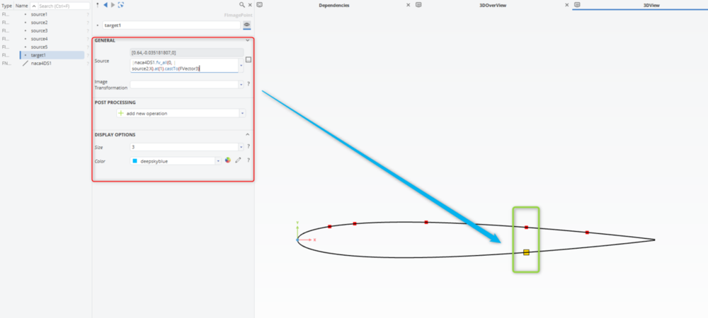
Basically, the fv_all command provides an objectlist.
MyCurve.fv(0,myPoint::x)
The command is applied to a curve.
The first argument "0" refers to x-axis
The second argument refers to the value on the selected axis. So result will be a list of points that have the same coordinate component value in the referred axis.
As seen on the picture above, the curve would have two locations with the same x-coordinate value. Using "at(1)" I pick the second item within the objectlist (0 would be used to pick the first one). And finally I cast the entity to a FVector3 type object.
Please let me know if you need further assistance.
Cheers
Ceyhan
Thank you so much. It worked really well. I didn't know how these function "at()" and "castTo()" worked. Thanks again, I couldn’t have pulled this off without your help!
-
My doubt is actually not hard, but with the actualization i lose a feature i used to use.
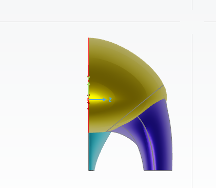
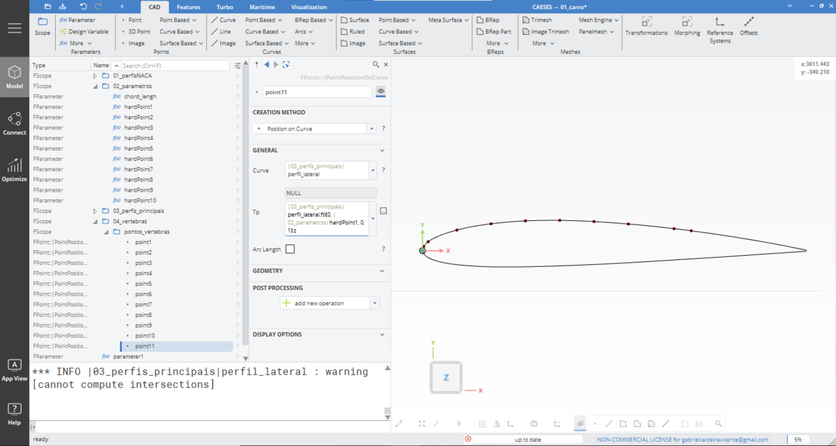
Here is the situation: I need to create some points on this curve and each point on the top has its correspondent on the bottom exactly on the same elevation in X axis. To do this i need to use the parameter witch corresponds to the elevation required, but in X axis the curve has 2 possible coordinates so that once i insert the function related to the creation of the point only one coordinate (on the top) is selected. Previously i could use "PointIntersection2D" and select a index, witch allowed me to choose any intersection the function would find. Here is an Image of the situation: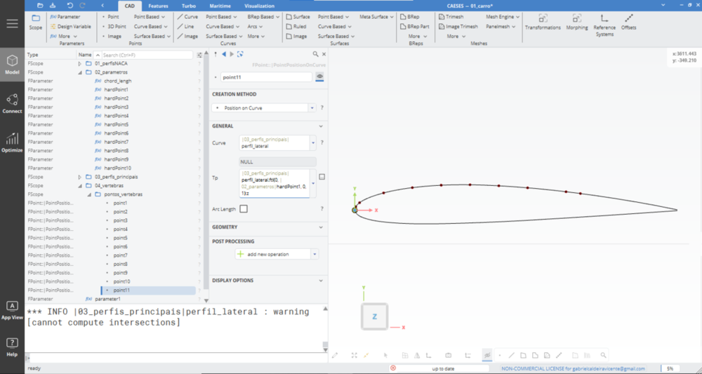
The question is: is there any function or any oder way to select another index on the curve?
P.S.: I could split the curve in two new curves, and repeat the steps, but i'd like to know if there is a solution like the feature i used to use.
-
 1
1
-
-
I got it! It was really easy, i just separated one of the lines in two, as Mr. Bastian Ahlf sad, and i got this, thank you. And Mr Carten Fuetterer thank you for your help and for you attention. I tried your suggestion too to have another option, but i could not reach the same result.
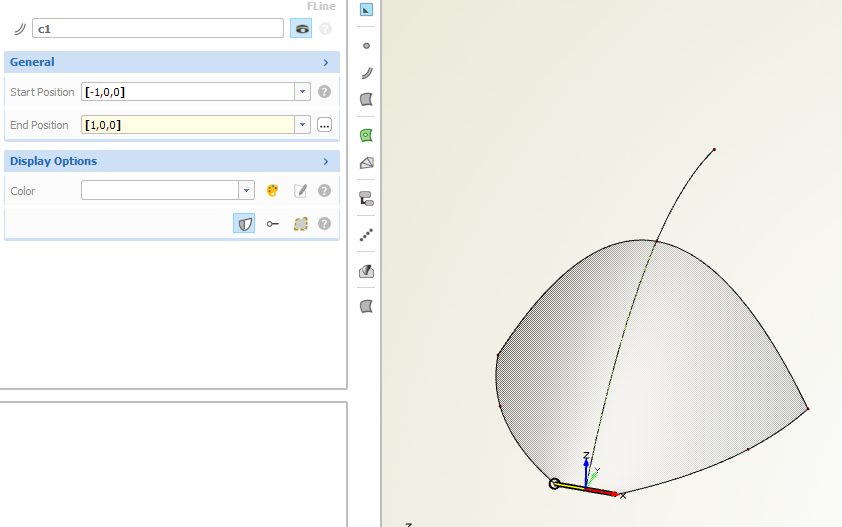 In the attached screenshot i got the same previous result that you got, but i couldn't collapse the line in just one point, i tried to use both start and end points at [0,0,0] and happens that the design gets some warnings:
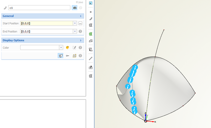 I'd be very grateful with you could explain me how you did it.
-
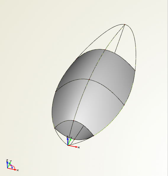 Hello, i'm still a beginner in CAESES and i'm trying to close this surface in both sides. I did the other surfaces using the surface feature "Coons Patch" which allows me to use four boundaries to create the surface. Now to close the ends of this design i've tried to use the feature "Sweep Surface", but i'm having a problem with it, like this one on the attached screenshot:
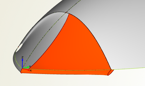 when i use the three boundaries, one as the path, other as the initial profile and the last one as the end profile and even changing their configuration i can't reach the surface i'd like to have, so could you guys give me a suggestion please.


Trying to create a rigid body
in General Modeling
Posted · Report reply
Hi Ceyhab,
I tried to do what you said, and fixed a problem i found in the back of it where i really had two open edges, but I'm still having the same issue i said previously, maybe because i can't find these other two open edges that rest. I believe that there is some problem with the intersection of the front "legs", but i don't know how to fix it. Could you help me to solve this problem?