


Mr. Helio Bailly Guimaraes
-
Content Count
6 -
Joined
-
Last visited
Posts posted by Mr. Helio Bailly Guimaraes
-
-
Hello Mr. Repolho,
Thanks for your interest.
The model I posted is to exemplify the usage of meta surface.
It gives you an idea in how to work with it.
It could be used as a hand to you to create your own model for instance.
TPO is just a parameter that can be varied by the user to visualize the transformation that is been done to the initial station that possibility the surface to be created. It is a "visualization tool" where you send the station To Position Of...
I hope it helps you to clear your doubts.
If you need any further support don't hesitate to contact me.
Regards,
HB
-
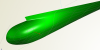
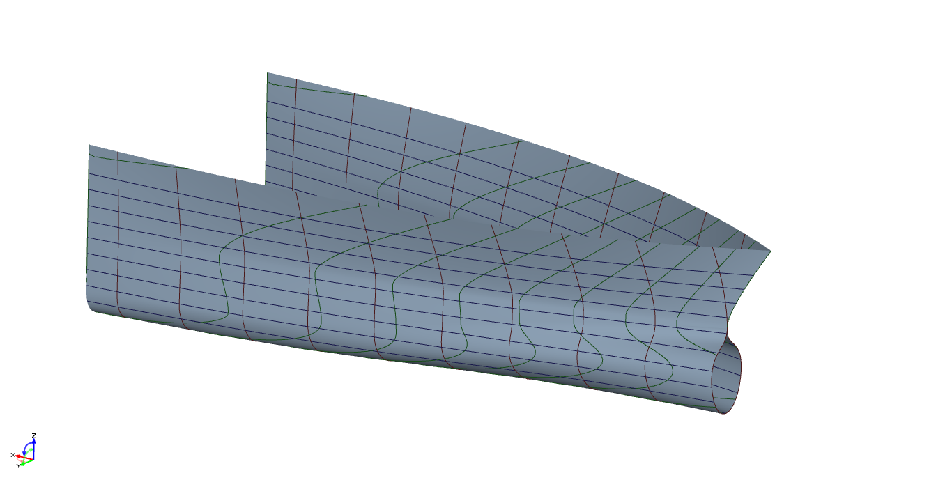
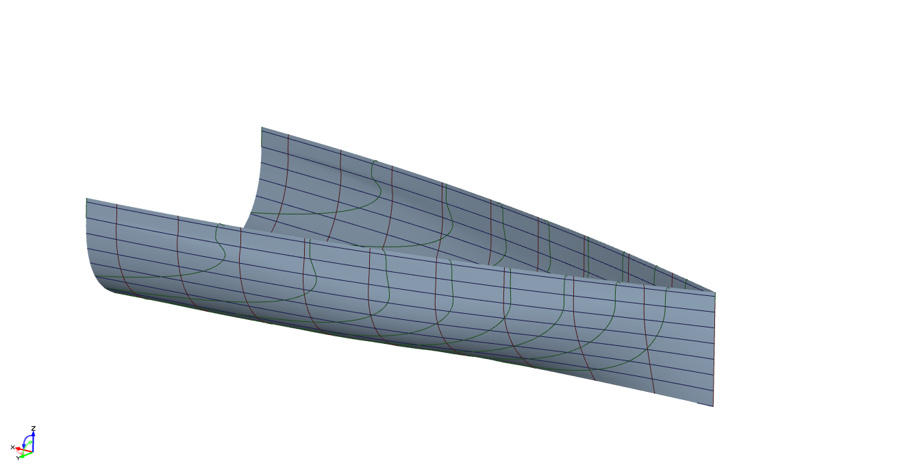
The following example consist of a single meta surface that is used to define the bow of a large varieties of ship kinds.
The model permit large variations of the shape from a typical bulbous bow of large vessels to vertical bows as seen in sailing boats, for instance.
First a station is defined by points as the keel, bilge, waterline and deck, plus some auxiliary points used to control the tangent of each curve, as to say to guarantee a smooth transaction between each section of the station.
Then those points "runs" along the X-axis varying the coordinates, defining the station at each "X" position of the station. The points and curves of each station are the same, however transformed as defined by some "curve functions", in function of X-position. Thus, the same curve I used to define the bilge at the aft zone I also use to define the bulb at the fore end of the bow.
This simple model shows the geniality, by simplicity, of a parametric model defined via meta surfaces.
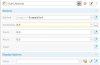
In this model the variables are:
-Beam
-Length
-Depth
-Draft
-Entrance Angle
-Stem Angle
-Bilge Radius
-Bulb Beam
-Bulb Height
Finally, TPOs is used to see the station variation along the X-axis.
Regards,
HB.

-
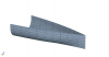
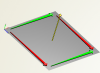
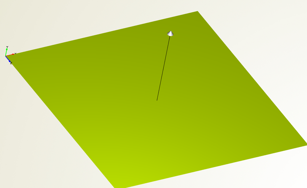
Sometimes the angle on a determined local of a surface is an important parameter.
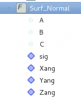
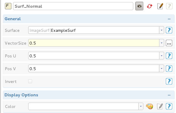
Thus, I created a simple feature which draws an arrow (surface normal) at a determined position (du, dv) for visualization.
Furthermore, it exports the angle of the normal referred to the global system (X, Y, Z) as (Xang, Yang and Zang).
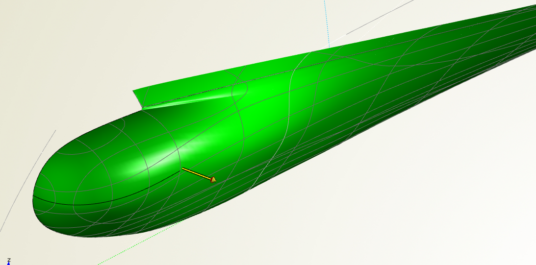
I used this feature on a project where I wanted to control the surface derivative at the aft part of my bulbous bow (see image attached) for example.
The feature can be used within any kind of surface (just need to change the argument type on the feature edition).
You can also visualize the normal arrow on the opposite direction of the normal of the surface, by simple clinking "invert". NOTE that the normal of the surface is still the same, only that the arrow is been draw in the opposite direction of the surface normal direction.
Hope it can be useful for you too.
Regards,

-
Hello Claus,
The objective function for the optimization problem would be the weight of steel (volume of the spring).
You can find it on the project folder: NumericalExample/toMinimize/ObjFunction
There are 8 constraints for this problem concerning maximum load, deflectiong from pre-load etc...
You can find the constraints definition at: NumericalExample/subjectTo
and the inequalities on Optimization tab/ Constraints
Details, equations and definitions can be found on the paper Jouni Lampinen - Ivan Zelinka (1999) which can be freely download on-line.
Or you can ask me, I will be pleased to give further information about the model and the example.
Best regards,
-
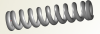
Coil Spring is a good example of mixed discrete-integer optimization, see reference: Jouni Lampinen - Ivan Zelinka (1999). "Mixed Integer-Discrete-Continuous Optimization By Differential Evolution, Part2: a practical example". In: Osmera, Pavel (ed.)(1999). Proceedings of MENDEL'99, 5th International Mendel COnference on Soft COmputing, June 9.-12.1999, Brno, Czech Replublic, pp.77-81. ISBN 80-214-1131-7.
The model is defined by D - Outer Diameter; d - wire diameter and N - Number of coils.
Where:
D is a continuous value.
d is given by an Allowable wire diameters table. The Design variable d refers to an index of the table.
N is an integer value.
Note: the last two design variables can be given as a non-integer value (for the usage of regular optimization processes). The appropriate integer value and allowable wire diameter from the table are defined in the feature "IntegerDiscrete".
Regards.


Generic Bow Defined by a Single MetaSurface
in General Modeling
Posted · Report reply
Hello again Mr. Repolho,
I'm not sure if I understood what you are trying to model. But, if you wanna to limit a parameters you could either use an "if" statement, please check our "insert snippet" feature to guide you through it, or you can set a relation between your parameter and your design variablel, for example:
Maximum value is "YY"
Minimum value is "zero"
then the design variable "D" that you use to control this dimension can be varied from 0 (zero) to 1 (one), and the value of the parameter used for the modeling is itself is defined by D*YY
I hope that can help you.
Best regards,
Helio.