


Britton Ward
-
Content Count
56 -
Joined
-
Last visited
Posts posted by Britton Ward
-
-
Claus,
Typical 2D section properties we use are like this in appropriate unit system of course:
Area: 92357056.735
Perimeter: 36720.890
Bounding box: X: 1165.227 -- 17331.991
Y: -329.077 -- 11344.873
Centroid: X: 8420.303
Y: 5290.858
Moments of inertia: X: 3120718178929088
Y: 7513980514853601
Product of inertia: XY: 3959967613135844
Radius of gyration: X: 5812.892
Y: 9019.864
Principal moments and X-Y directions of centroid:
I: 4.856E+14 along [0.952 -0.306]
J: 1015503441212061 along [0.306 0.952]
Thanks,
Britt -
Hi,
One feature I have been looking for (that I don't think is available) is to be able to retrieve sectional properties from a number of cross sections or planar surfaces.
I am often doing structural analysis of hydrofoils and being able to retrieve sectional interia/torsion constant information and operate on them would be a huge help.
https://github.com/robbievanleeuwen/section-properties is a potential option but I haven't had the time to try and integrate it myself.
Looking forward to seeing what CAESES 4.5 has in store for us ..
Britt
-
Thank you.. works great. I've found this to be a really useful example.
-
Has anyone had success opening this model with version 4.3.1? I've been trying this afternoon but it either hangs on the loading or if loads CAESES locks up entirely and has to be force shut down. There is a statement INFO Mathematical Function: sqrt warning written to the console but am unable to edit the model to see where the problem is.
-
Joerg.
This is an interesting blog post that has some application for me. Is there a tutorial project for this? Where can I get the Response Surface feature?
Britt
-
Hi,
I've been connecting some OpenFOAM files and I wondered if it was possible to dynamically Comment or Uncomment a series of lines in an input file template.
For example in the attached U file the specification for the boundary conditions changes depending on the inflow velocity vector.
Depending on the value of Yaw I would like to comment/uncomment select lines.
Is there a way to implement this type of edit efficiently in CAESES?
Britt
/*--------------------------------*- C++ -*----------------------------------*\| ========= | || \\ / F ield | OpenFOAM: The Open Source CFD Toolbox || \\ / O peration | Version: 2.4.x || \\ / A nd | Web: www.OpenFOAM.com || \\/ M anipulation | |\*---------------------------------------------------------------------------*/FoamFile{version 2.0;format ascii;class volVectorField;location "0";object U;}// * * * * * * * * * * * * * * * * * * * * * * * * * * * * * * * * * * * * * //#include "include/initialConditions"dimensions [0 1 -1 0 0 0 0];internalField uniform (0 0 0);boundaryField{minX{type zeroGradient;}maxX{type rampedVelocity;finalVelocity $flowVelocity;rampingTime $rampTime;rampingScheme $rampScheme;value $internalField;}minY{// yaw <= 0degtype zeroGradient;// // yaw > 0deg// type rampedVelocity;// finalVelocity $flowVelocity;// rampingTime $rampTime;// rampingScheme $rampScheme;// value $internalField;}maxY{// yaw >= 0degtype zeroGradient;// // yaw < 0deg// type rampedVelocity;// finalVelocity $flowVelocity;// rampingTime $rampTime;// rampingScheme $rampScheme;// value $internalField;}minZ{type zeroGradient;}maxZ{type zeroGradient;}ship{type movingWallVelocity;value uniform (0 0 0);}}// ************************************************************************* // -
Hi,
I'm back puzzling over this issue of concatenating multiple software connectors. When I run a design study the process runs successfully through the first two software connectors but the third [and therefore 4th] are never triggered.
The first simply takes a result file from the previous steps, along with some template files, executes and returns a file that is used by the 4th connector.
I've tried to follow the instructions above.
The 2nd Step is called "RAGOO" a custom tool that produces the output result file I need as a *.vin file.
[This tool could generate a lot of these vin files ... is there anyway to grab all of the *.vin files for input in the next directory?]The 3rd Step is a performance prediction program WinDESIGN [customized and executed via python script] in the software connector I used the Input file selector to select the file from the RAGOO output. I then edited it because the filename will change based on the design name as follows:
Ragoo.getResults().getResultFileName(4_RagooPrep|43_RagooInputParam|ModelID + "_01.vin")
The WINDESIGN step produces a csv file named: 4_RagooPrep|43_RagooInputParam|ModelID + ".csv"
The 4th Step is an excel spreadsheet called by a python script called EXCELIRCRMP this needs the csv output file from WINDESIGN to execute.
I use the Software connector selection to pick the output then edit it to incorporate the modename as follows:
WinDesign.getResults().getResultFileName(4_RagooPrep|43_RagooInputParam|ModelID + ".csv")
For each of the third and fourth steps I don't have a specific feature that refers to output from the previous steps. I have tried to add a string parameter based on output from the previous step to try and force it but with no luck.
Do I have to create some dummy feature to force the path manager to act once the 2nd step is available? Any ideas on how to make a simple one?
Looking at the dependency tree from an output parameter read from the 4th computation it appears that all the dependencies are in order as expected.
Anxious to flex this new license on a range of variants but I am stuck until I can get it working reliably!
Britt
-
Hi,
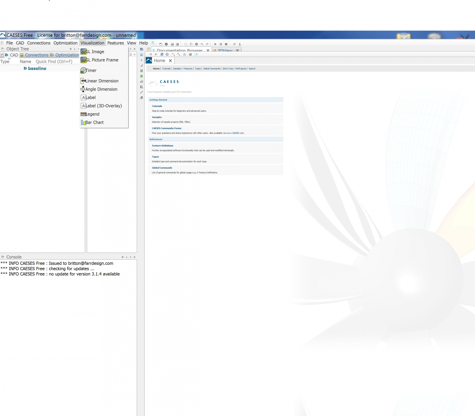
Have just moved to a new laptop with a 4k -retina style display. Is any work planned to tune CAESES for these high resolution displays? While the program runs fine... there are display issues with icons appearing over text in the menu bar, tab bar justification and icons being too small to use reliably.
This is a problem with the onboard display so does not limit my usage with external monitors.
Screen shot to show what I am seeing.

-
Hi,
I've got a complex string of external computations lined and rather than fixed file names the basefile name is generated from the design name.
In this case I am getting an input file from a previous computation using the command:
getResultsDir(Ragoo) + 4_RagooPrep|43_RagooInputParam|ModelID + "_01.vin"
Hoping this will trigger the computation to begin when this file becomes available.
I'm wondering if it is possible to use wild cards in these situations as I may have more than 1 of the vin files..
would getResultsDir(Ragoo) +"*.vin" retrieve all the *.vin files produced by the previous computation and copy them to my new computation input folder?
Likewise for results files will using wildcards + extension work?
Thanks,
Britt
-
I think I fixed it.
Strangely though when running the baseline design I have to manually execute the second external computation but when I run the design assembler it now run all the way through.!
Britt
-
Thanks for taking the time to write that summary. It confirmed most of what I thought I understood.
The issue I was having is I have a geometry file for an external computation in a custom format being written as a text file so it took a little wrangling to get it seen as an input.
I was beginning to exercise my model and I'm seeing something else that is causing issues that you may be able to help me with.
I'm using the Design Assembler to create a single variant.
When I execute the Design Engine it creates the folders:
DesignAssembler_01
and DesignAssembler_01_des000
For some reason the model executes the first external computation and puts the results in the main DesignAssembler_01 directory. It then exports the geometry file to the DesignAssembler_01/input directory but does not execute the second external computation.
It then creates the des000 directory. It runs the first external computation again successfully but the required feature geometry export does not happen and the second external computation fails.
All file calls use getResultsDir() or getInputDir()
Why is that toplevel DesignAssembler_01 directory populated at all? I would have thought it should only execute for each des_**** ?
Any thoughts?
Britt -
Arne,
Thanks for your thoughts. I'll give it a go ... it seems I am pretty good at finding these little issues.. you all must be getting tired of me!
Is there a concise summary on the preferred methods of how a project accessing external software should be using the file structure commands?
I seem to be stumbling a bit in making sure program B) gets the right file from program A) .. and what the framework is actually doing with moving files from input directories etc.?
I gather that you need to use getInputDir() and getResultsDir() in order to insure that the dependencies are correctly constructed?
I'm really close through trial and error but would be nice if there was a tutorial that walked you through the actual disk processes that occur ..
Britt
-
Hi,
I have setup to parse a text file with a list of values by adding the file as a results template. I have then manually selected the results variables and then linked these to parameters.
After doing this I realized some items were missing from the result file and so regenerated it with the new values appended.
I can't see a way to replace the results template with the updated one in the software connector and so I cannot add the new values as additional results parses and parameters.
It seems I have to delete the results template and re-add it and then manually redefine all the results parses I did previously. It is some 50 values so it is a bit time consuming.
Is there a way to refresh the results template without losing my results definitions?
Separately, it would be really nice if there were functionality to read a list of name, value pairs and automatically derive the parameter names from the name list in one click?
Also, some of my software now output XML files directly. Do you have any plans to add some XML parsing functionality into the software connector template selection? It would be nice to use XML query tags to pull items from a file .. something for a rainy day!
-
Claus,
3.1.2 seemed to fix all the issues I was having! So far so good.
Britt
-
HI Claus/Stefan,
Thanks for your comments.. Claus. ... I new I had seen that edit button before in the environment.. thanks for reminding me.
Agree its possible and can be desireable to split surfaces with discontinuities into their own surfaces .. might be an interesting general feature to have to automate it?
Even if my surface did not have a discontinuity I would have the problem at the bow however as the reskinning algorithm misses the detail at the bow round and creates unfairnesses.
I'll see what happens with 3.1.2 when it is released.
Thanks,
Britt
-
Hi,
Encountered an interesting problem today that I wonder if you can help me address>
Attached project will help outline the steps.
Some description for the project:
1) I import a IGES 128 surface into Hull -> Surf000
2) I create an image of this surface where the only change is I alter the U parameter range for the Image surface.
3) Select the image surface and export the iges file and load into a program where you can see the control net layout.
4) Create a copy of the image surface and export an IGES file of this surface and load into a program to see the control net.
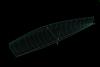
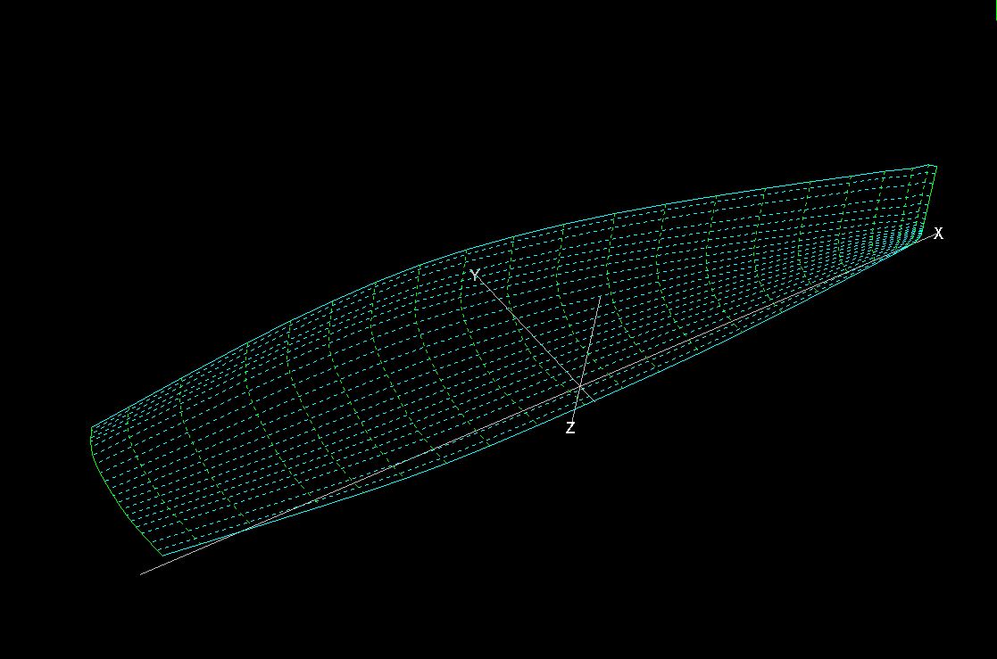
The IGES import is a NURBS surface that contains multiplicities and some complex geometry at the bow. All other CAD programs have no trouble with this topology. [OriginalNet.jpg]
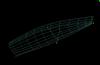
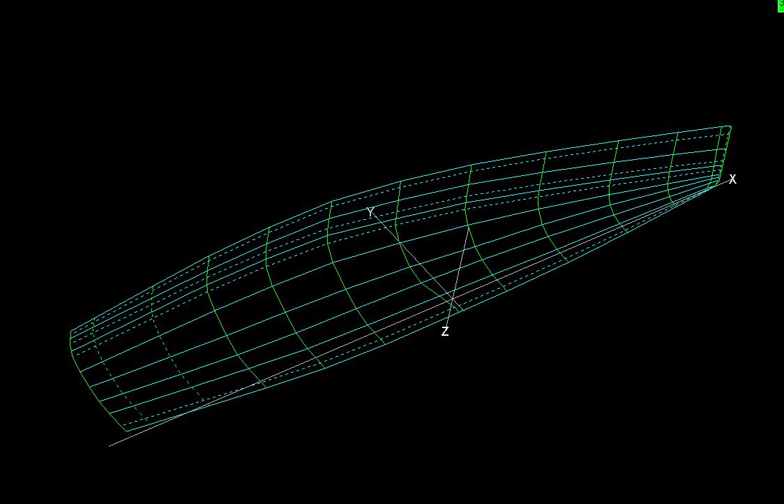
The IGES file from STEP 2 retains the initial files topology but is shortened in the U parameter as desired. [imageIGESExport.jpg]
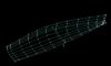
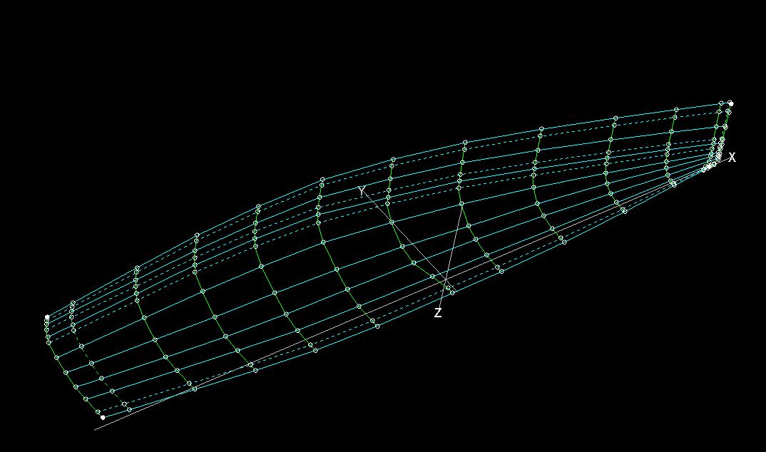
The IGES file from STEP 4 has reskinned the surface topology completely and lost definition at the multiplicity and at the stem creating an unfaithful copy with significant unfairness. [CopyIGESExport.jpg]
If I write my own feature to operate directly on the control points of the s1 surface I am only able to access the reskinned results when I really need the original topology. Why is it than an IGES export of the image surface retains the topology but the copied surface or a feature accessing it cannot?
This is a bit of a showstopper for me at the moment. Hope you have some suggestions.
Britt
-
Thanks Arne,
Your ensemble computation idea is exactly what I had in mind .. sometime in the future!
When I'm running full simulations I am farming to a linux cluster. I successfully did this with a SUP board design using Fine/Marine where the parametric model generated 100 geometries and each was meshed and run on the cluster. That one had a single figure of merit so was relatively simple compared to the full sailing yacht problem!
Britt
-
Arne,
Thanks for the response. Your proposal to send the whole optimization to the SSHRM is exactly what I was thinking of in terms of a client server model .. hope it comes in 3.2!
Ref my first point. The link you pointed me to addresses some of what I was after but I'll describe the process in more detail.
I break it down this way, although the FFW has only one type of design parameter, in our processes we have "design parameters" that vary the shape geometry and "state variables" that reflect the conditions for analysis. I would use a design engine to produce a series of geometric designs. Each of these designs needs to be evaluated using a CFD code at 50 - 300 different conditions [Heel Angle, Leeway Angle, Vs, Appendage Conditions, Loading conditions etc.] Typically each design would be run over the same matrix of conditions. The results from these simulations would be processed to produce a force/moment response surface that is run in a separate optimizer to predict the best boat speed, heel, yaw etc. for different true wind speed and true wind angle conditions. Finally this result would be evaluated against a race model incorporating weather to produce a final figure of merit for the optimization.
All of the program sequencing and post processing if possible with FFW. I just don't see an easy way to spawn the SSHRM processes for each design operating condition in an efficient manner.
I'm sure this is a problem many of your users face as it would seem very rare that a single point analysis is a sufficient figure of merit for optimization.
Any suggestions would be appreciated.
Britt
-
Hi,
As time permits I am working on integrating the framework into our design process with the hope I can prove its worth, get some contracts and buy a full license.
One area that I see potentially being difficult is the need for each design to be run over many different operating conditions. Essentially the design will be modified by its parameters and each design will have to be run over a range of operating conditions [Vs, Heel, Yaw, ....]. I'm not clear if there is a way to a) use the design engines as implemented in the FFW to generate these nested simulations and b) if there are any plans to update SSHResourceManager to allow these "subtasks"?
Also wondering if there are any plans to allow a client-server model when running large optimizations using SSHRM? Some of these can get quite large and resource intensive but they are so closely coupled to the interface that it can lock you out of doing other productive work ..
Just some idle thoughts.
Britt
-
Claus/Stefan,
Back onto this quickly. I think I discovered my problem. I was incorrectly populating the knot vectors when I read my file in so that they were defaulting to an even distribution and losing the multiplicity. I have reviewed the code and fixed my read statements and all seems consistent now.
Britt
-
Arne,
Completely understand that there has to be some differentiation between the versions. Would be nice to use the simple Newton-Raphson in a model creation capacity rather than a variant generation one though!
Hopefully I will land a project soon that will allow me to get a proper commercial license...!
Britt
-
Hi,
Just want to see if something has changed or if my memory is failing me ..
At end of last year I built a model of a paddle board with full Fine/Marine integration.
As part of the model I used the Newton-Raphson solver to adjust the hull depth parameter to achieve a target volume before finalizing a design variant.
I had thought the use of the N-R solver in this capacity was available in CAESES but the latest version seems to indicate that use of the solvers in any context are only available with a commercial license? Perhaps I had developed this with the trial license previously without realizing.
Britt
-
Claus/Arne,
I implemented Arne's poposal and it seems to work fine!
-
Hi.
I've written a small program to do some geometry modifications and have set it up as a local software connector.
The executable call is as follows:
"C:/Work/Programming Projects/FFDMorph/FFDMorph/Debug/FFDMorph.exe" "C:\Program Files (x86)\FRIENDSHIP-SYSTEMS\CAESES-FFW\my projects\SRFTest\SRFTest\manual_results\baseline\input\export.srf" "C:\Program Files (x86)\FRIENDSHIP-SYSTEMS\CAESES-FFW\my projects\SRFTest\SRFTest\manual_results\baseline\input\FFDMorph.in"the arguments to be passed to the program consist of the two file names with paths.Because my program is fortran it requires the two path strings to be surrounded by quotes as above. I can't seem to figure out how to combine the two filename strings within the framework into a single string that contains the quotes to close the first path and open the second with a space between.FSExport|f1:file.getFileName() + " " + FFDInputFile:file.getFileName() -> what syntax is needed to get the quotes to appear in here?"C:\Program Files (x86)\FRIENDSHIP-SYSTEMS\CAESES-FFW\my projects\SRFTest\SRFTest\manual_results\baseline\input\export.srf C:\Program Files (x86)\FRIENDSHIP-SYSTEMS\CAESES-FFW\my projects\SRFTest\SRFTest\manual_results\baseline\input\FFDMorph.in"or is there a way to have more than one argument for a software connector?Thanks
License Server Down
in Installation
Posted · Report reply
Hi, CAESES won't launch and says it can't access the license server? Is it down?